


Chapter 4 - Advanced Programming Techniques
Chapter 4 - Advanced Programming Techniques
4-1. Objectives
Upon completion of this chapter, you will know
”how to take advantage of the order of program execution in a PLC to perform unique functions.
”how to construct fundamental asynchronous and clocked flip flops in ladder logic including the RS, T, D, and JK types.
”how the one-shot operates in a PLC program and how it can be used to edgetrigger flip flops.
”how to use uni-directional and bidirectional counters PLC programs.
”how sequencers functions and how they can be used in a PLC program..
”how timers operate and the difference between retentive and non-retentive timers.
4-2. Introduction
In addition to the standard logical operations that a PLC can perform, seasoned PLC programmers are aware that, by taking advantages of some of the unique features and characteristics of a PLC, some very powerful operations can be performed. Some of these are operations that would be very difficult to realize in hardwired relay logic, but are relatively simple in PLC ladder programs. Many of the program segments in this chapter are rather “cookbook” by nature. The student should not concentrate on memorizing these programs, but instead, learn how they work and how they can be best applied to solve programming problems.
4-3. Ladder Program Execution Sequence
Many persons new to PLC ladder logic programming may tend to think that, because a PLC executes its program synchronously (i.e., from left to right, top to bottom), instead of asynchronously (i.e., each relay operates whenever it receives a signal) it is a hindrance to the programming task. However, after gaining some experience with programming PLCs, the programmer begins to learn how to use this to their advantage. We will see several useful program segments in this chapter that do this. Keep in mind that the order of the rungs in these programs is critical. If the rungs are rearranged in another order, it is likely that these programs will not operate properly.
4-1

Chapter 4 - Advanced Programming Techniques
4-4. Flip Flops
As we will see in the following several sections, a few of the circuits you learned to use in digital electronics can be developed for use in a ladder diagram. The ones we will study are the R-S, D, T and J-K Flip Flops and the One Shot. The One Shot will supply the clock pulse for the D, T and J-K Flip Flops. These are functions that can be very useful in a control system and tend to be more familiar to the student since they have been studied in previous courses.
4-5. RS Flip Flop
The R-S Flip Flop is the most basic of the various types. It has two inputs, an R (reset) and an S (set). Turning on the R input resets the flip flop and turning on the S input sets the flip flop. As you may recall from the study of this type of flip flop, the condition where R and S are both on is an undefined state. The truth table for an R-S Flip Flop is shown in Table 4-1.
|
|
|
|
R |
S |
Q |
Q' |
|
|
|
|
0 |
0 |
Q |
Q' |
0 |
1 |
1 |
0 |
1 |
0 |
0 |
1 |
1 |
1 |
X |
X |
|
|
|
|
Table 4-1 - Truth
Table for RS Flip
Flop
For the purpose of our discussion, a 1 in the table indicates an energized condition for a coil or contact (if energized, a normally closed contact will be open). An X in the table indicates a don't care condition. The ladder diagram for such a circuit is shown in Figure 4-1.
4-2
Chapter 4 - Advanced Programming Techniques
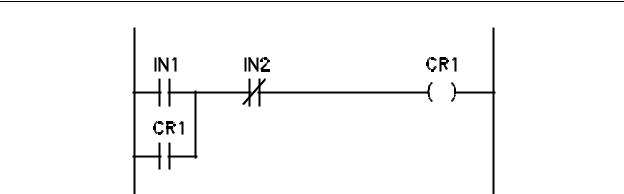
Figure 4-1 - RS Flip Flop
S = IN1, R = IN2
If you study Figure 4-1, you can see that if IN2 energizes, coil CR1 will de-energize and if IN2 de-energizes and IN1 energizes, coil CR1 will energize. Once CR1 energizes, contact CR1 will close, holding coil CR1 in an energized state even after IN1 de-energizes until IN2 energizes to reset the coil. Relating to the truth table of Table 4-1, you can determine that IN1 is the S input and IN2 is the R input to the flip flop. You may notice in the truth table that both a Q and Q' outputs are indicated. If an inverted Q signal is required from this ladder, one only needs to make the contact a normally closed CR1 (a normally closed contact is open when it's coil is energized).
4-6. One Shot
As with the oscillator covered in a previous chapter, the one shot has its own definition in the world of ladder logic. In digital electronics a one shot is a monostable multivibrator that has an output that is on for a predetermined length of time. This time is adjusted by selecting the proper timing components. A one shot in ladder logic is a coil that is on for one scan and one scan only each time it is triggered. The length of time the one shot coil is on depends on the scan time of the PLC. The one shot can be triggered by an outside input to the controller or from a contact associated with another coil in the ladder diagram. It can also be a coil that energizes for one scan automatically at startup. It is this type we will study first, then the externally triggered type.
A one shot that comes on for one scan at program startup is shown in Figure 4-2.
4-3
Chapter 4 - Advanced Programming Techniques
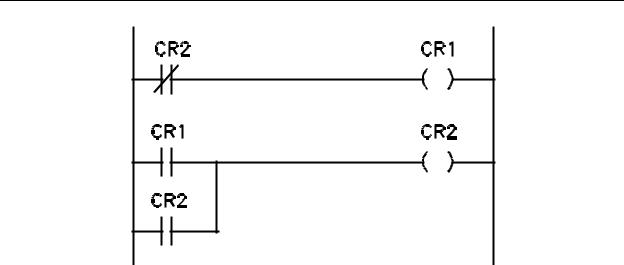
Figure 4-2 - Automatic One Shot
This one shot consists of two rungs of logic. The two rungs are placed at the beginning of the ladder diagram. Coil CR1 is the one shot coil. If you analyze the first rung, you can see that, since all coils are off at the beginning of operation, normally closed contact CR2 will be closed (coil CR2 is de-energized). This will result in coil CR1 being energized in the first rung of the ladder. The PLC then moves to the second rung which contains the remaining part of the one shot. When the controller solves the contact logic of this rung, normally open contact CR1 will be closed (CR1 was energized in the first rung). Normally open contact CR2 is open (CR2 is still de-energized from startup). Since contact CR1 is closed, coil CR2 will be energized in the second rung. The PLC will then proceed with solutions of the remaining rungs of the ladder diagram. After I/O update, the controller will return to rung one. At this time contact CR2 will be open (coil CR2 was energized on the previous scan). The solution to the contact logic will be false and coil
CR1 will be de-energized. When the PLC solves the logic for rung two, the contact logic will be true because even though coil CR1 is de-energized making contact CR1 open, coil
CR2 is still energized from the previous scan. This makes contact CR2 closed which will keep coil CR2 energized for as long as the controller is operating. Coil CR2 will remain closed because each time the controller arrives at the second rung, contact CR2 will be closed due to coil CR2 being energized from the previous scan. The result of this ladder is that coil CR1 will energize on the first scan of operation, de-energize on the second scan and remain de-energized for the remaining time the controller is in operation. On the other hand, coil CR2 will be de-energized until the first solution of rung two on the first scan of operation, then energize and remain energized for the remaining time the controller is in operation. Each time the controller is turned off then turned back on, this sequence will take place. This is because the controller resets all coils to their de-energized state at the onset of operation. If any operation in the ladder requires that a contact be closed or open for the first scan after startup, this type of network can be used. Coil CR1 will remain
4-4

Chapter 4 - Advanced Programming Techniques
closed for the length of time that is required to complete the first scan of operation regardless of the time required.
Notice, however, that we have two coils, CR1 and CR2 that are complements of each other. Whenever one is on, the other is off. In ladder logic, this is redundant because if we need the complement of a coil, we merely need to use a normally closed contact from the coil instead of a normally open contact. For this reason, a simpler type of one shot that is in one state for the first scan and the other state for all succeeding scans can be used.
This is a coil that is off for the first scan and on for all other scans. Any time a contact from this coil is required, a normally closed contact may be used. This contact would be closed for the first scan (the scan that the coil is de-energized) and open for all other scans (the coil is energized). Such a ladder diagram is shown in Figure 4-3.
Figure 4-3 - One Shot Ladder Diagram
This one shot only consists of one rung of logic which is placed at the end of the ladder diagram. Notice that the contact logic for the rung includes two contacts, one normally open and one normally closed. Since both contacts are for the same coil (CR2), no matter what the status of CR2 the contact logic will be true. This can be proven by writing the Boolean expression for the contact logic and reducing. An expression which
contains a signal OR it's complement is always true ( A + A = 1). This means that CR2 will be off until the controller arrives at the last rung of logic. When the last rung is solved, the result will be that CR2 is turned on. Each time the controller arrives at the last rung of logic on each scan, the result will be the same. CR2 will be off for the first scan and on for every scan thereafter until the controller is turned off and back on. Any rung that requires a contact that is on for the first scan only would include a normally closed CR2 contact.
4-5
Chapter 4 - Advanced Programming Techniques
Any rung that requires a contact that is off for the first rung only would contain a normally open CR2 contact.
The other type of one shot mentioned is one that is triggered from an external source such as a contact input from inside or outside the controller. We will study one triggered from an input contact. Once the operation is understood, it does not matter what the reference for the contact is, coil or input, the operation is the same. The ladder diagram for such a one shot is shown in Figure 4-4.
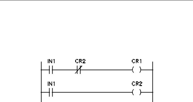
Figure 4-4 - Externally Triggered One Shot
You will notice that this type of one shot is also composed of two rungs of logic. In this case, the portion of the ladder that needs the one shot contact is place after the two rungs. In operation, with IN1 de-energized (open), the two coils, CR1 and CR2 are both de-energized. On the first scan after IN1 is turned on, CR1 will be energized in the first rung and CR2 in the second. On the second scan after IN1 is turned on, CR1 will deenergize due to the normally closed CR2 contact in the first rung. CR2 will remain on for every scan that IN1 is on. The result is that coil CR1 will energize for only the first scan after IN1 turns on. After that first scan, coil CR1 will de-energize. The system will remain in that state, CR1 off and CR2 on until the scan after IN1 turns off. On that scan, coil CR1 will de-energize in the first rung and coil CR2 will de-energize in the second rung. This places the system ready to again produce a one shot signal on the next IN1 closure with coil CR1 controlling the contact that will perform the function. If a contact closure is required for the function requiring the one shot signal, a normally open CR1 contact may be used. If a contact opening is required, a normally closed CR1 contact may be used.
This type of one shot function is helpful in implementing the next types of flip flops, the D, T and J-K Flip Flops. The D flip flop may be designed with or without the one shot while the T and J-K flip flops require a clock signal, in this case we will use IN1 for our input clock and a one shot to produce the single scan contact closure each time IN1 is turned on.
4-7. D Flip Flop
4-6
Chapter 4 - Advanced Programming Techniques
As you will recall from digital courses, a D flip flop has two inputs, the D input and a trigger or clock input. In operation, the state of the D input is transferred to the Q output of the flip flop at the time of the trigger pulse. The truth table for a D flip flop is shown in Table 4-2.
|
|
|
|
D |
CL |
Qn |
Qn+1 |
|
|
|
|
0 |
0 |
X |
Qn |
0 |
1 |
X |
0 |
1 |
0 |
Q |
Qn |
1 |
1 |
X |
1 |
|
|
|
|
Table 4-2 - Truth Table
for D Flip Flop
The headings of the columns in Table 4-2 should be explained. The column labeled Qn contains the state of the flip flop Q output prior to the trigger and the column labeled Qn+1 contains the state of the Q output of the flip flop after the application of the trigger. An X indicates a don't care situation. A 1 in the CL column indicates that the clock makes a 0 to 1 to 0 transition.
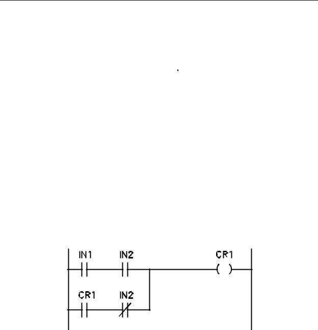
Figure 4-5 - Ladder Diagram for D Flip Flop
IN1 = D, IN2 = Trigger
A ladder D Flip Flop is shown in Figure 4-5. The D Flip Flop shown is a one rung function with two inputs, IN1 and IN2, and one coil CR1. IN1 is defined, in this case, as the D input and IN2 is defined as the trigger. The D flip flop can use either a non timed contact closure, or, a single scan contact closure from a one shot. We will discuss the latter style
4-7

Chapter 4 - Advanced Programming Techniques
next. This is the first case in which normally open and normally closed contacts referenced to the same input (IN2). We are able to utilize this type of contact arrangement because when the controller solves the contact logic, the states of the input contacts are dependent upon their states at the last I/O update. Let us assume that the controller has just been set into operation and that all coils are de-energized. Also, at this time we will let IN1 and IN2 be off, resulting in normally open contacts IN1 and IN2 being open and normally closed IN2 contact being closed. In this state, coil CR1 will remain de-energized on every scan. Now, let IN1 (the D input) turn on. Each time the controller solves the rung in this state, the upper branch of logic (IN1 and IN2 contacts) will be false because IN2 is still off and the lower branch of contacts (CR1 and IN2) will be false because CR1 is de-energized. This means that coil CR1 will remain de-energized. If IN2 is now turned on, the upper branch of contacts will become true because IN1 and IN2 will both be on. The result is that coil CR1 will energize on the first scan after IN2 turns on and will remain energized as long as
IN2 is on. IN2 is the trigger signal for the flip flop. When the trigger signal is turned off (IN2), coil CR1 will remain in the energized state. This is because the lower branch of contacts (CR1 and IN2) will be true (CR1 is energized and IN2 is off). If IN2 (the trigger) turns on and off again and IN1 is still on, the same events will occur; the upper branch of contacts will be true which will hold coil CR1 energized while IN2 is on and the lower branch of contacts will be true and hold CR1 energized when IN2 turns off. This is what we want. If the D input to the flip flop is true, we want the Q output to stay in a 1 state after the trigger. Let us now discuss the effect of the D input being set to a 0. On the first scan after IN2 (the trigger) turns on, if IN1 (D) is off, coil CR1 will de-energize. This is because both branches of contacts will be false, the upper because IN1 is off and the lower because
IN2 is on. On subsequent scans, coil CR1 will remain de-energized because, again, both branches of contacts will be false, the upper with IN2 off and the lower because CR1 was de-energized.
Let us now discuss the operation of a D flip flop having D input IN1 with a single scan trigger invoked from an outside input contact, IN2. The truth table is still as in Table 4-2. The ladder diagram for such a system is shown in Figure 4-6.
4-8