

Chapter 9 – Digital Meets Analog – ADC and DAC
how the ADC value translates to light intensity’. I have no idea what the data means other than the amount of light is inversely proportional to the data sent back, just like it is supposed to be. I guess we could try to calibrate it in Lumens, or furlongs or something… nah, Let’s move on.
Temperature Meter
We will measure the temperature in Fahrenheit and use an array of constants to convert the value from a voltage to a temperature. The table is from the Butterfly code.
// Positive Fahrenheit temperatures (ADC-value) const int TEMP_Fahrenheit_pos[] PROGMEM =
{// from 0 to 140 degrees
938, 935, 932, 929, 926, 923, 920, 916, 913, 909, 906, 902, 898, 894, 891, 887, 882, 878, 874, 870, 865, 861, 856, 851, 847, 842, 837, 832, 827, 822, 816, 811, 806, 800, 795, 789, 783, 778, 772, 766, 760, 754, 748, 742, 735, 729, 723, 716, 710, 703, 697, 690, 684, 677, 670, 663, 657, 650, 643, 636, 629, 622, 616, 609, 602, 595, 588, 581, 574, 567, 560, 553, 546, 539, 533, 526, 519, 512, 505, 498, 492, 485, 478, 472, 465, 459, 452, 446, 439, 433, 426, 420, 414, 408, 402, 396, 390, 384, 378, 372, 366, 360, 355, 349, 344, 338, 333, 327, 322, 317, 312, 307, 302, 297, 292, 287, 282, 277, 273, 268, 264, 259, 255, 251, 246, 242, 238, 234, 230, 226, 222, 219, 215, 211, 207, 204, 200, 197, 194, 190, 187,
};
void getTemperature()
{
char fahr[]= {'0','0','0','\0'};
int ADCresult = 0; int i = 0;
// Initialize the ADC to the temperature sensor channel //ADC_init(0);
ADMUX = 0;//input;
ADCresult = ADC_read();
/* The pgm_read_word() function is part of WinAVR and reads a word from the program space with a 16-bit (near) address,
220
Chapter 9 – Digital Meets Analog – ADC and DAC
as in the table. When a table entry is found that is less than the ADC result we break and i equals the temperature in Fahrenheit. Pretty clever, huh? Wish I thought of it, but I borrowed it from the WinAVR version of the Butterfly code. I'll quit owning up to all this theft and from now on if you see something clever (the good kind of clever) just assume that I stole it. */
for (i=0; i<=141; i++)
{
if (ADCresult > pgm_read_word(&TEMP_Fahrenheit_pos[i]))
{
break;
}
}
/* Next we convert the integer ADCresult to a string that we can transmit to the PC. Let’s use a function from the standard library. We add #include <stdlib.h> to our file. Then we can use the itoa() function, which converts and integer to an ASCII character array terminated with '\0'. */
itoa(i, fahr, 10);
// Send the temperature to the PC sendString("The temperature is "); sendString(fahr);
sendString(" degrees Fahrenheit.\r");
}
The @#%#&*#!!!! Volt Meter
If you read the debugging tale, you know where the “@#%#&*#!!!!” comes from.
void getVolt()
{
char voltintpart[]= {'0','0','0','\0'}; char voltfractpart[]= {'0','0','0','\0'}; int intpart = 0;
int fractpart = 0; int ADCresult = 0;
221
Chapter 9 – Digital Meets Analog – ADC and DAC
ADCresult = ADC_read(); intpart = ADCresult/50; fractpart = ADCresult%50;
itoa(intpart, voltintpart, 10); itoa(fractpart, voltfractpart, 10);
// Send the voltage to the PC sendString("The reading is "); sendChar(voltintpart [0]); sendChar('.'); sendChar(voltfractpart [0]); sendString(" volts.\r");
}
The initializer and the parseInput functions:
Open a new directory, ADC, and copy the Demonstrator and PC_Comm .c and .h files from the last project. Change the Demonsrator.c by adding the following functions and the above functions. Compile, load, and test.
#include "PC_Comm.h" #include "Demonstrator.h"
void initializer()
{
//Calibrate the oscillator: OSCCAL_calibration();
//Initialize the USART USARTinit();
ADC_init(1);
// say hello
sendString("\rPC_Comm.c ready to communicate.\r");
//identify yourself specifically sendString("You are talking to the ADC demo.\r");
//show commands
sendString("Commands:\r");
sendString("light - returns a light value\r"); sendString("temp - returns the temperature in fahrenheit\r"); sendString("volt - returns a voltage value\r");
}
222
Chapter 9 – Digital Meets Analog – ADC and DAC
void parseInput(char s[])
{
// parse first character switch (s[0])
{
case 'l':
if((s[1]=='i') && (s[2]=='g')&& (s[3]=='h') && (s[4 =='t')) getLight();
break; case 't':
if((s[1] == 'e') && (s[2] == 'm')&& (s[3] == 'p')) getTemperature();
break; case 'v':
if((s[1] == 'o') && (s[2] == 'l')&& (s[3] == 't')) getVolt();
break; case 'd':
if((s[1]=='e') && (s[2]=='m') && (s[3]=='o') && (s[4]=='?')) sendString("You are talking to the ADC demo.\r");
break;
default:
sendString("\rYou sent: '"); sendChar(s[0]);
sendString("' - I don't understand.\r"); break;
}
s[0] = '\0';
}
Using ADC
When you turn on the Butterfly you should see the following on HyperTerminal:
PC_Comm.c ready to communicate. You are talking to the ADC demo. Commands:
light - returns a light value
temp - returns the temperature in fahrenheit volt - returns a voltage value
Type in:
223
Chapter 9 – Digital Meets Analog – ADC and DAC
temp
The response looks like:
The temperature is 78 degrees Fahrenheit.
Turn on a fan! 78 degrees Fahrenheit is too darn hot to work. Put a flashlight on the light sensor and type in:
light
The response is a low number for a high light level:
The light reading is 236 somethings.
Using the room light and type in:
light
The response is a low number for a medium light level:
The light reading is 645 somethings.
Put your finger over the sensor to block the room light and type:
light
The response is a low number for a low light level:
The light reading is 1004 somethings.
Type in:
volt
The response looks like:
224
Chapter 9 – Digital Meets Analog – ADC and DAC
The reading is 0.0 volts.
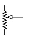
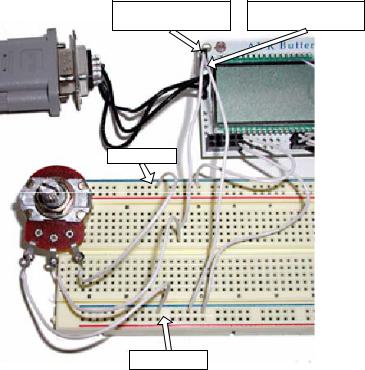
Urrrrmmmm… Oh yes, if we are going to measure voltage, we need to put a voltage on pin 2 of J407 on the Butterfly. But first we need solder some wires on a potentiometer so we can vary a voltage. The JAMECO parts list has a 10 k Ohm potentiometer listed. As in Figure 28, we connect one side to +3v and the other to GND, then we connect the middle to pin 1 of J407, the ADC connector, as shown in Figure 26. By turning the potentiometer shaft we move a wiper connected to the center wire up or down. The full +3v is dropped across the potentiometer and the center leg ‘sees’ a voltage proportional to the resistance above and below it.
|
+3v |
|
3 k Ohms above |
10 k Ohms |
+2.1v |
Potentiometer |
|
|
7 k Ohms below |
GND
Figure 28: Potentiometer Schematic
225
Chapter 9 – Digital Meets Analog – ADC and DAC
Pin 1 of J407 connects to center leg of potentiometer
Butterfly +3v
Pin21 of J407 connects to Butterfly Ground
Butterfly Ground
Figure 29: Voltage measurement
Now we can get some responses. Try turning the potentiometer to various settings and in response to a volt command you should see something like:
volt
The reading is 2.1 volts. volt
The reading is 3.0 volts. volt
The reading is 1.4 volts. volt
The reading is 0.4 volts.
226