

Chapter 2: Quick Start Guide
Hardware
Constructing Your Development Platform
Light Sensor |
Joystick |
|
ADC
USART
USI
PORTB
Pin 2
PORTB |
GND +3V |
JTAG |
PORTD |
GND +3V |
ISP |
|
Pin 1 |
Pin1 |
|||||
|
|
|
|
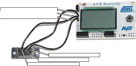
Figure 2: The Butterfly front
Solder the female headers to the ADC, PORTB, and PORTD lands. Note that the square pads are pin1 and that PORTB and PORTD seem to have 10 pins, but they don’t, pins 9 and 10 are ground and power respectively (see Figure 2).
The RS-232 Connection:
Communication with the PC requires three lines: TXD, RXD, and GND. The TXD is the transmit line (data from the PC to the Butterfly), RXD is the receive line (data from the microcontroller to the PC) and GND is the common ground. Notice that there is a bit of relativity in this equation, the microcontroller’s RXD wire is the PC’s TXD wire and vice versa. I can’t count the number of times I’ve
21
Chapter 2: Quick Start Guide
done stupid things like connecting the microcontroller’s RXD pin to the DB-9 RXD pin, because I didn’t think ‘RXD – receive - relative to what?’
The parts list has a DB-9 female solder cup RS-232 connector. Follow the illustrations in Figure 3.
USART (J406) connector: pin1 RXD
USART (J406) connector: pin2 TXD
USART (J406) connector: pin3 GND
Solder cup backside pin 5 - GND
Solder cup backside pin 3 - TXD
Solder cup backside pin 2 - RXD
Figure 3: RS-232 connections.
NOTICE HOW THE RXD AND TXD LINES CROSS OVER – PAY CAREFUL ATTENTION AS IT IS EASY TO GET THESE REVERSED.
Constructing the power supply:
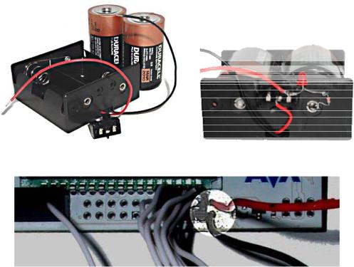
The Butterfly comes with a CR2450 coin battery that will power the LCD for a long time, but will be used up quickly by the RS-232 connection and our experiments. Remove the coin battery and construct a battery pack with parts from the JAMECO parts list (Appendix 7) using the following pictures. Be sure and get the power, red wire, and ground, black wire, correct: as shown in Figure 4 and Figure 5.
NOTE: ALL THE ILLUSTRATIONS SHOW PORTD WITH AN 8-PIN HEADER AND THE POWER WIRES SOLDERED IN PLACE. THE PARTS KIT SPECIFIES 10-PIN CONNECTORS FOR BOTH PORTS B AND D. USE THE 10-PIN HEADER ON PORTD AND INSERT RATHER THAN SOLDER THE POWER WIRES.
22
Chapter 2: Quick Start Guide
Figure 4: Battery holder, switch, and batteries.
Figure 5: External battery connection to Butterfly
A few days after making the power supply I left it on all night, so I added an LED (Figure 4) to the switch so that I’d know that it was on. You can solder the long leg of an LED to the rightmost pin on the switch, where the +3v goes to the Butterfly, and then solder a 330 resistor to the short leg and the resistor to the rivet at the base of the battery on the right. The LED is lit when the switch is to +3V.
Test your Connection using Brays Terminal:
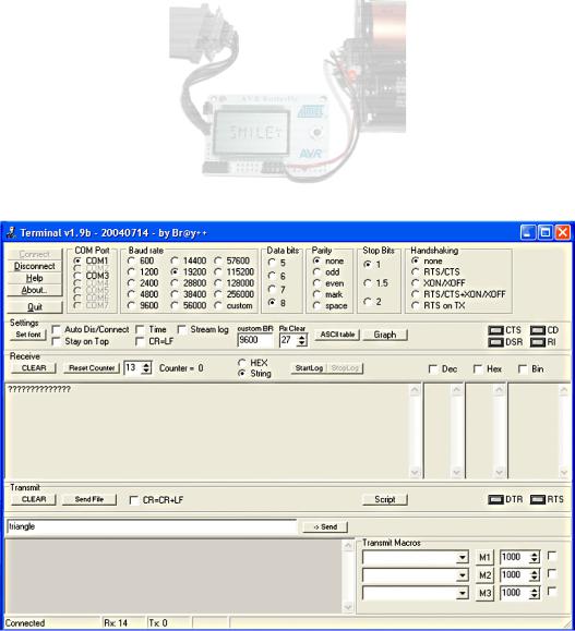
Hook your RS-232 cable to the Butterfly as in Figure 6. The run Bray’s Terminal, (well, Br@y++’s to be exact – available at http://bray.velenje.cx/avr/terminal and http://www.smileymicros.com) and configure it as in Figure 7 with the radio buttons set to select your COM port, 19200 Baud rate, 8 Data bits, parity of none, 1 Stop bits, and no handshaking. Click the connect button. Turn on your Butterfly
23
Chapter 2: Quick Start Guide
power supply, then with the joystick button centered press it and watch the stream of ?????? question marks that should be coming from the Butterfly. This is the Bootloader telling you that it is alive and ready to be boot loaded, or perhaps it is just curious as to what’s going on?
Figure 6: Butterfly hooked up to RS-232
Figure 7: Bray's Terminal
24
Chapter 2: Quick Start Guide
If you don’t get the string of question marks, then try the other COM ports (in Figure 7 only COM1 and COM3 are shown for my machine, yours may be different. Press disconnect then connect and try again. If it still doesn’t work, carefully check that the RS-232 cable is connected. Try again. Still no? Recheck that you’ve got the DB-9 soldered correctly to your Butterfly. Try again. Still no? Is it turned on? If you move the joystick upward do you get the LCD scrolling message? Yes? Turn it off and on and press the center again. Still no? If its not working by this point go back and meticulously retry everything you can think of, including passing a dead chicken over the setup while chanting voodoo hymns. It took me a while to get all this running and I supposedly know what I’m doing, so don’t feel bad if this is a little harder than you might hope. (You get what you pay for).
In a moment you will scoop out the Butterfly’s brains, toss them aside, and stick in some brains that Igor got from a garage sale, so let’s do one final test on the Butterfly as it came out of the package. If all goes well, you will eventually be able to reload the Butterfly’s original brains, but all seldom goes will, as Igor will readily attest.
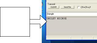
With the Butterfly hooked up to the RS-232 port and the Br@y++ Terminal running, turn the Butterfly on and click the joystick up to get the LCD scrolling. Move the joystick straight down three times till you see ‘Name’ then move the joystick to the right twice till you see ‘Enter name’ then move the joystick straight down once and you will see ‘Download name’ then push down the joystick center for a moment until you see ‘Waiting for input’. Now write a name in the bottom text panel of the Br@y++ Terminal (Figure 8) and hit enter (or push it gently if you prefer). The name you entered should be scrolling across the LCD as shown in Figure 6.
Use this gray window to send characters to the Butterfly, not the white one above.
Figure 8: Enter name to send to the Butterfly
25
Chapter 2: Quick Start Guide
Let’s Blink Some LED’s:
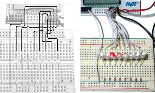
Figure 9: Blinky wiring diagram and photo of wired board
All the parts are listed in the JAMECO parts list Appendix 1. Put the LEDs in the breadboard with the short leg on the resistor side. Use the 330-Ohm resistors to jumper to the ground strip. You’ll need to make a bunch of jumper wires, cut 9 pieces about 4 inches long strip each end about 3/8 inch, and connect them to the breadboard as shown in Figure 9, with the right most LED connected to pin 1 of PORTD (Figure 2) and subsequent pins connected sequentially. The pins are numbered with the odd pins on the bottom of the PORTD land and the even pins on the top. Cut a 6” wire and use it to connect the ground strip to the ground pin of PORTB as shown.
Now connect your RS-232 cable between the computer and the RS-232 connector you soldered to the Butterfly. Your hardware should look like Figure 10.
26