Добавил:
Upload Опубликованный материал нарушает ваши авторские права? Сообщите нам.
Вуз: Предмет: Файл:

MusculoSkeletal Exam

.pdf
Скачиваний:
85
Добавлен:
14.05.2015
Размер:
22.79 Mб
Скачать

Chapter 13 The Ankle and Foot

Calcaneofibular

ligament Tear of Calcaneofibular

ligament

Figure 13.95 Inversion stress test of the ankle. Excessive foot inversion indicates a tear of the calcaneofibular ligament.

Inversion Stress Test

This test is performed if the anterior drawer test result is positive. This test uncovers damage to the calcaneofibular ligament, which is responsible for preventing excessive inversion. The patient is positioned either seated at the edge of the table or in the supine position (Figure 13.95). Cup the patient’s heel in your hand and attempt to invert the calcaneus and talus. Excessive inversion movement of the talus within the ankle mortise is a positive test result.

Test for Stress Fractures

Stress fractures are common in the bones of the lower leg and foot. If a stress fracture is suspected, the area of localized tenderness over the bone can be examined with a tuning fork. Placing the tuning fork onto the painful area will cause increased pain in a stress fracture. This test should not be relied on without the benefit of x-rays or bone scans.

Test for Morton’s Neuroma

A Morton’s neuroma develops in the second or third web space where the interdigital nerves branch (Figure 13.96). By holding the foot with your hand

Morton's

neuroma

Figure 13.96 Morton’s neuromas develop in the second or third web space where the interdigital nerves branch. They may be painful to palpation and metatarsal compression.

425

The Ankle and Foot Chapter 13

Figure 13.97 Flexible flat feet are only visible in the standing

Figure 13.98 Rigid flat feet remain flat in any position.

position. The normal plantar arch is noted in the seated position.


and squeezing the metatarsals together, a click may be heard. This occurs in patients with advanced Morton’s neuroma and is called a Moulder’s click.

Tests for Alignment

Deviations from normal alignment of the forefoot and hindfoot are common. Abnormal weight-bearing forces due to these deviations cause pain and disorders such as tendinitis, stress fractures, corns, and other pressure problems. Frequently, abnormal alignment patterns, which are initially flexible, become rigid. The most common abnormality is a hindfoot valgus with compensatory forefoot varus, which is known as pes planus or a flat foot.

Test for Flexible Versus Rigid Flat Foot

A curved medial longitudinal arch should normally be observed when the patient is both sitting and standing. If a medial longitudinal arch is noted in the seated

position and disappears when the patient stands, this is referred as a flexible flat foot (Figure 13.97). If the patient does not have a visible arch in the seated position, this is known as a rigid flat foot (Figure 13.98).

Test for Leg–Heel Alignment

This test is used to determine whether a hindfoot valgus or varus condition exists. The patient is placed prone with the test leg extended and the opposite foot crossed over the posterior aspect of the knee on the test leg. A vertical line is drawn along the lower third of the leg in the midline (Figure 13.99). Another vertical line is drawn in the midline of the Achilles insertion into the calcaneus. While the subtalar joint is held in neutral position (described earlier in the chapter), the angle formed by the two lines is measured. An angle of approximately 0–10 degrees is normal. If the angle is less than 0 degree, the patient has a hindfoot varus.

Test for Forefoot–Heel Alignment

The patient is placed in the supine position with the feet extending off the end of the table. While maintaining

426

Chapter 13 The Ankle and Foot

Plane 1

Plane 1


>10°


Plane 2

Plane 2

<0°


Varus

Valgus

Figure 13.99 Testing for hindfoot varus and valgus. Four lines are drawn on the posterior aspect of the leg, two lines in the distal third of the leg in the midline and two lines at the attachment of the achilles tendon to the heel. (A) Here, plane 1 and plane 2 form an angle that is more than 10 degrees and the patient has hindfoot varus. (B) The angle formed in between the two planes is less than 0 degree and hence the patient has hindfoot valgus.

the subtalar joint in neutral, take the forefoot with the other hand and maximally pronate the forefoot (Figure 13.100). Now imagine a plane that extends through the heads of the second to the fourth metatarsals. This plane should be perpendicular to the vertical axis of the calcaneus. If the medial side of the foot is elevated, the patient has a forefoot varus. If the lateral side of the foot is elevated, the patient has a forefoot valgus.

Test for Tibial Torsion

By age 3, the tibia is externally rotated 15 degrees. At birth, the tibia is internally rotated approximately 30 degrees. Excessive toeing-in may be caused by internal tibial torsion (Figure 13.101). With the patient sitting on the edge of the table, the examiner imagines a plane that is perpendicular to the tibia and extends through the tibial tubercle. A plane extending through the ankle mortise should be externally rotated 15 degrees (Figure 13.102). If this plane is externally rotated less than 13 degrees, the patient has

internal tibial torsion (Figure 13.103). If the plane is rotated more than 18 degrees, the patient has external tibial torsion.

Radiological Views

Radiological views are presented in Figures 13.104 through 13.107.

G= Hindfoot

H= Midfoot

I= Forefoot

S = Sesamoid bones

A = Ankle

C = Calcaneus

Cu = Cuboid

T = Talus

N = Navicular

S = Spur

MT = Metatarsal

427

The Ankle and Foot Chapter 13

Plane A

90°

Plane B

Figure 13.100 Testing for forefoot varus and valgus. With the subtalar joint in neutral position, an imaginary plane (B) passing through the heads of the metatarsals should be perpendicular to the vertical (A) axis. If the medial side of the foot is elevated, there is a forefoot varus deformity. If the lateral side of the foot is elevated, the patient has forefoot valgus deformity.

428

Chapter 13 The Ankle and Foot

Figure 13.101 Toeing-in may be caused by internal tibial torsion.

Posterior

Plane through

ankle mortise

15˚

Medial

Lateral

Tibia

Anterior

Figure 13.102 A plane extending through the ankle mortise should be externally rotated 15 degrees.

429

Posterior

Plane through


ankle mortise

Medial

Lateral

Tibia

Anterior

Figure 13.103 An internal tibial torsion, the ankle mortise faces medially less than 13 degrees.

Figure 13.104 Anteroposterior view of the foot.

430

Chapter 13 The Ankle and Foot

Figure 13.105 Lateral view of the ankle and foot.

Figure 13.106 Oblique view of the foot.

431

The Ankle and Foot Chapter 13

Figure 13.107 Sagittal view of the ankle mortise (*).

432

Chapter 14

Gait

Gait Chapter 14

The Lower Extremity

This section is not intended as a definitive treatise on the lower extremity, but rather it is to serve as the introduction to the lower-extremity physical examination, based on the principles presented in the introductory chapters of this book. This section reviews the more salient aspects of lower-extremity structure, function, and physical examination. Its intended objective is to present the entire lower extremity as a whole. With this perspective, it is hoped that the examiner will become sensitized to the anatomical relationships that place an individual at risk of injury. Its purpose is to provide the examiner (and patient) with the means for identifying, addressing, and avoiding causes of injury.

The linkage and interdependence of articulations and structures of the lower extremity, back, and pelvis must be considered when evaluating and diagnosing complaints of the lower extremity.

The lower extremities are pillars on which the body is supported. They permit and facilitate movement of the body in space. They accomplish this task through a series of linkages: the pelvis, hip, knee, ankle, and foot. Each of these linkages has a unique shape and function. Together they permit the lower extremity to efficiently accommodate varying terrains and contours.

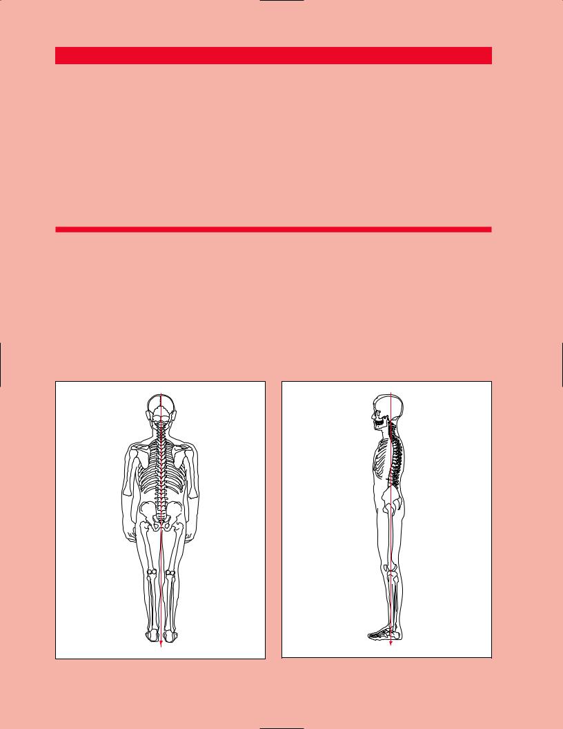
The body’s center of gravity is located in the midline, 1 cm anterior to the first sacral vertebra. During bipedal stance, the body’s weight is supported equally over each lower limb, creating a downward compression load on the joints of the lower extremities. During the unilateral support phase of gait, however, the body’s center of gravity is medial to the supporting limb. Therefore, during unilateral support, the hip, knee and ankle of the supporting limb will experience not only a compression load, but also a varus (inward) rotational destabilizing force referred to as a moment. This destabilizing force must be counteracted by a muscular effort. Otherwise, the body will fall to the unsupported side (Figure 11.1).

At the base of each pillar is the foot and ankle complex. The ankle and foot are structures uniquely designed to tolerate a lifetime of significant cyclic loads of varying rates while traversing any terrain. The key to the successful functioning of these structures lies in the extraordinary stability of the ankle, and the impact attenuation and surface accommodation properties of the foot. The stability of the ankle may well explain its ability to resist the inevitable mechanical degeneration
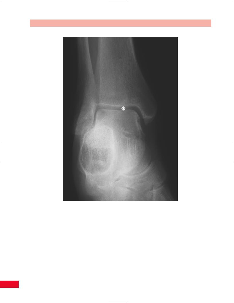
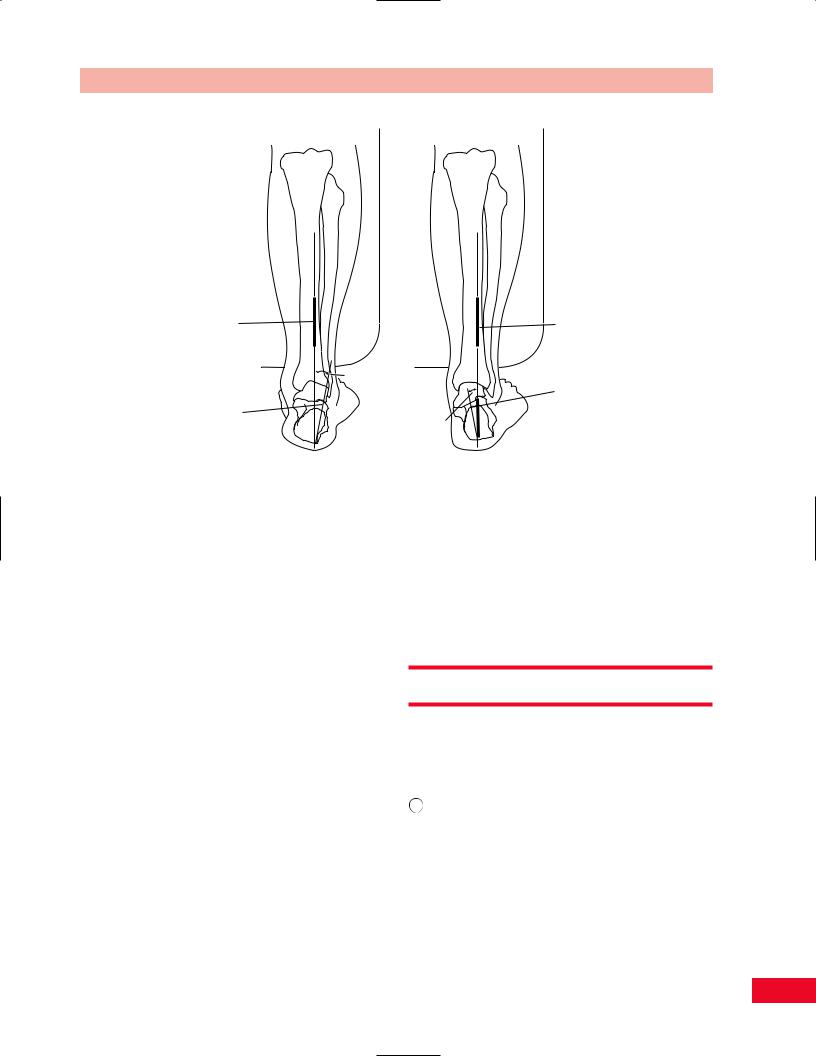
Tibia

Fibula

Tibial

plafond

Talus

Calcaneus

Figure 14.1 The talus is a rectangular bone keystoned within a rigid mortise formed by the medial malleolar process of the tibia, the tibial plafond, and the lateral malleolus.

expected in such a small articulation exposed to such repetitive stress. The ankle structure is that of a keystone recessed into a rigid mortise (Figure 14.1). It is because of this extraordinary stability, unless lost secondary to injury, that the ankle does not demonstrate the normal osteoarthritic changes with aging found in all other synovial joints. This is even more impressive in light of the significant loads that are being supported by the relatively small articular surface of the ankle joint (approximately 40% that of the hip or knee) during weight-bearing activities such as running. However, this stability carries with it an inability to accommodate rotational and angular stresses that would otherwise ultimately lead to compromise of the ankle joint if they were not first buffered by the foot below. The suppleness of the foot articulations, that is, subtalar pronation, accommodates varying surface topographies to reduce these torques. The arches attenuate the repetitive stress of the weight-bearing loads that occur during locomotion. This system of complementary functions forces recognition of the ankle and foot not as isolated regions, but rather as a single ankle–foot mechanism.

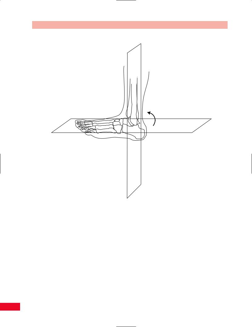
The talus holds the key to the intimate structural and mechanical relationship that exists between the ankle and foot. As the part of the ankle that is held within a rigid mortise, the talus is limited to flexion– extension motion. As a part of the foot, the talus must
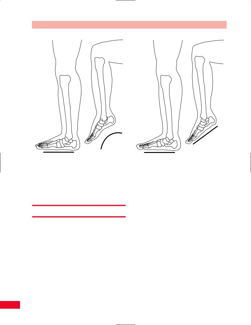
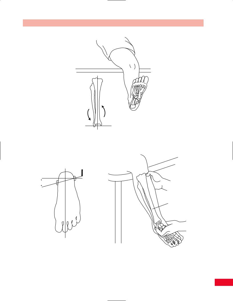
434

Соседние файлы в предмете [НЕСОРТИРОВАННОЕ]