

B.Crowell - Conservation Laws, Vol
.2.pdfExample: how torque depends on the direction of the force
Question: How can the torque applied to the wrench in the figure be expressed in terms of r, |F|, and the angle θ?
Solution: The force vector and its F component form the hypotenuse and one leg of a right triangle,
|
|
r |
|
|
|
|
|
|
|
|
F |
θ |
F |
|
|
θ |
|
|
||
|
|
|
F |
|
||
|
|
F |
|
|
θ |
|
|
|
|
|
|
|
|
|
|
and the interior angle opposite to F equals θ. The absolute |
||||
|
|
value of F |
can thus be expressed as |
|
||
|
|
F |
= |
|F| sin θ |
, |
|
|
|
leading to |
|
|
|
|
|
|
|τ| |
= |
r |F| sin |
θ . |
|
r |
|
Sometimes torque can be more neatly visualized in terms of the quan- |
||||
|
tity r shown in the figure on the left, which gives us a third way of express- |
|||||
|
|
|||||
|
|
ing the relationship between torque and force: |
|
|||
|
F |
|τ| |
= |
r |F| . |
|
|
|
|
|
|
|||
Of course you would not want to go and memorize all three equations for torque. Starting from any one of them you could easily derive the other r two using trigonometry. Familiarizing yourself with them can however clue
you in to easier avenues of attack on certain problems.
The torque due to gravity
Up until now we’ve been thinking in terms of a force that acts at a single point on an object, such as the force of your hand on the wrench. This is of course an approximation, and for an extremely realistic calculation of your hand’s torque on the wrench you might need to add up the torques exerted by each square millimeter where your skin touches the wrench. This is seldom necessary. But in the case of a gravitational force, there is never any single point at which the force is applied. Our planet is exerting a separate tug on every brick in the Leaning Tower of Pisa, and the total gravitational torque on the tower is the sum of the torques contributed by all the little forces. Luckily there is a trick that allows us to avoid such a massive calculation. It turns out that for purposes of computing the total gravitational torque on an object, you can get the right answer by just pretending that the whole gravitational force acts at the object’s center of mass.
[Answer to self-check on previous page.] 1, 2, and 4 all have the same sign, because they are trying to twist the wrench clockwise. The sign of 3 is opposite to the signs of 1, 2, and 4. The magnitude of 3 is the greatest, since it has a large r and the force is nearly all perpendicular to the wrench. Torques 1 and 2 are the same because they
have the same values of r and F . Torque 4 is the smallest, due to its small r.
Section 5.4 Torque: the Rate of Transfer of Angular Momentum |
101 |
r
F
Discussion question B.
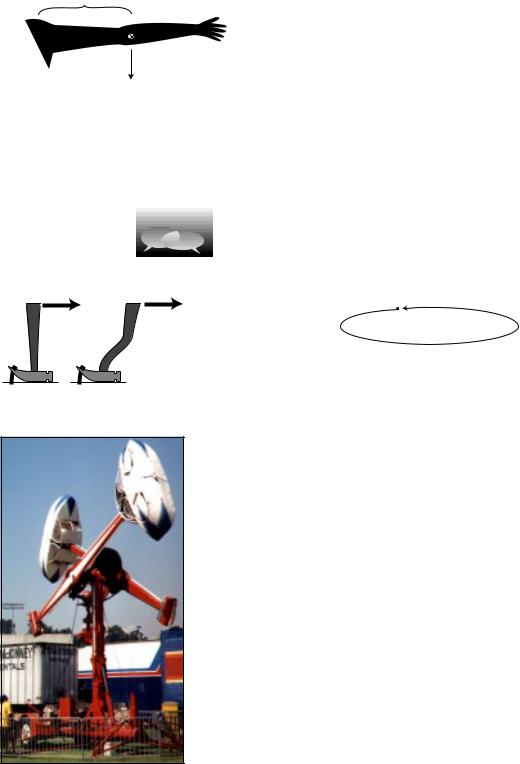
Example: gravitational torque on an outstretched arm
Question: Your arm has a mass of 3.0 kg, and its center of mass is 30 cm from your shoulder. What is the gravitational torque on your arm when it is stretched out horizontally to one
side, taking the shoulder to be the axis?
Solution: The total gravitational force acting on your arm is |F| = (3.0 kg)(9.8 m/s2) = 29 N .
For the purpose of calculating the gravitational torque, we can treat the force as if it acted at the arm’s center of mass. The force is straight down, which is perpendicular to the line connecting the shoulder to the center of mass, so
F = |F| = 29 N .
Continuing to pretend that the force acts at the center of the arm, r equals 30 cm = 0.30 m, so the torque is
τ = r F = 9 N.m .
Discussion Questions
A. This series of discussion questions deals with past students' incorrect
reasoning about the following problem.
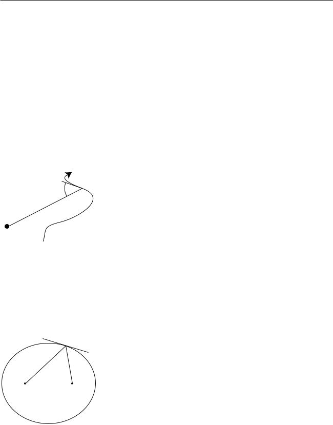
Suppose a comet is at the point in its orbit shown in the figure. The only force on the comet is the sun's gravitational force.
comet
F
 sun
sun
Throughout the question, define all torques and angular momenta using the sun as the axis.
(1)Is the sun producing a nonzero torque on the comet? Explain.
(2)Is the comet's angular momentum increasing, decreasing, or staying the same? Explain.
Explain what is wrong with the following answers. In some cases, the answer is correct, but the reasoning leading up to it is wrong.
(a)Incorrect answer to part (1): "Yes, because the sun is exerting a force on the comet, and the comet is a certain distance from the sun."
(b)Incorrect answer to part (1): "No, because the torques cancel out."
(c)Incorrect answer to part (2): "Increasing, because the comet is speeding up."
B. Which claw hammer would make it easier to get the nail out of the wood if the same force was applied in the same direction?
C. You whirl a rock over your head on the end of a string, and gradually pull in the string, eventually cutting the radius in half. What happens to the rock’s angular momentum? What changes occur in its speed, the time required for one revolution, and its acceleration? Why might the string break?
D. A helicopter has, in addition to the huge fan blades on top, a smaller propeller mounted on the tail that rotates in a vertical plane. Why?
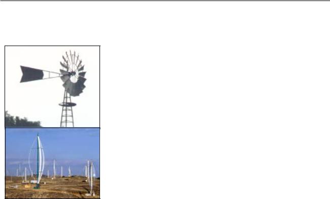
E. The photo shows an amusement park ride whose two cars rotate in opposite directions. Why is this a good design?
Discussion question E.
102 |
Chapter 5 Conservation of Angular Momentum |
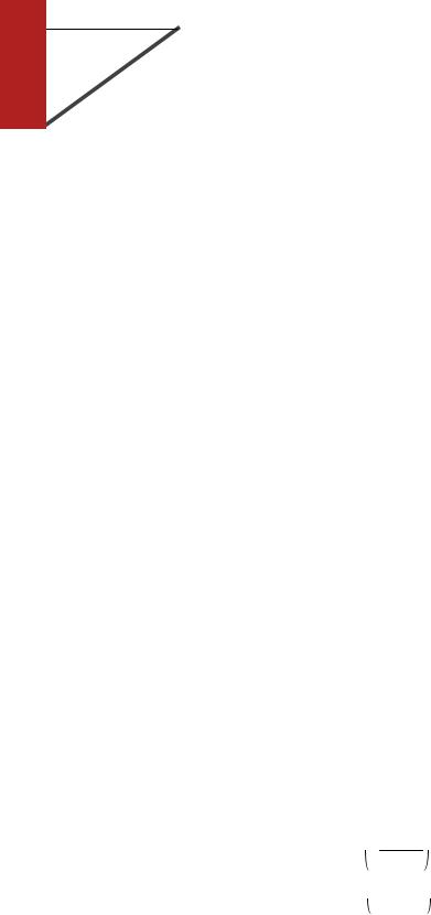
5.5Statics
The windmills are not closed systems, but angular momentum is being transferred out of them at the same rate it is transferred in, resulting in constant angular momentum. To get an idea of the huge scale of the modern windmill farm, note the sizes of the trucks and trailers.
Equilibrium
There are many cases where a system is not closed but maintains constant angular momentum. When a merry-go-round is running at constant angular momentum, the engine’s torque is being canceled by the torque due to friction.
When an object has constant momentum and constant angular momentum, we say that it is in equilibrium. This is a scientific redefinition of the common English word, since in ordinary speech nobody would describe a car spinning out on an icy road as being in equilibrium.
Very commonly, however, we are interested in cases where an object is not only in equilibrium but also at rest, and this corresponds more closely to the usual meaning of the word. Trees and bridges have been designed by evolution and engineers to stay at rest, and to do so they must have not just zero total force acting on them but zero total torque. It is not enough that they don’t fall down, they also must not tip over. Statics is the branch of physics concerned with problems such as these.
Solving statics problems is now simply a matter of applying and combining some things you already know:
•You know the behaviors of the various types of forces, for example that a frictional force is always parallel to the surface of contact.
•You know about vector addition of forces. It is the vector sum of the forces that must equal zero to produce equilibrium.
•You know about torque. The total torque acting on an object must be zero if it is to be in equilibrium.
•You know that the choice of axis is arbitrary, so you can make a choice of axis that makes the problem easy to solve.
In general, this type of problem could involve four equations in four unknowns: three equations that say the force components add up to zero, and one equation that says the total torque is zero. Most cases you’ll encounter will not be this complicated. In the example below, only the equation for zero total torque is required in order to get an answer.
Section 5.5 Statics |
103 |
Example: a flagpole
Question: A 10-kg flagpole is being held up by a lightweight horizontal cable, and is propped against the foot of a wall as shown in the figure. If the cable is only capable of supporting a tension of 70 N, how great can the angle α be without breaking the cable?
α Solution: All three objects in the figure are supposed to be in equilibrium: the pole, the cable, and the wall. Whichever of the three objects we pick to investigate, all the forces and torques on it have to cancel out. It is not particularly helpful to analyze the forces and torques on the wall, since it has forces on it from the ground that are not given and that we don’t want to find. We could study the forces and torques on the cable, but that doesn’t let us use the given information about the pole. The object we need to analyze is the pole.
The pole has three forces on it, each of which may also result in a torque: (1) the gravitational force, (2) the cable’s force, and (3) the wall’s force.
We are free to define an axis of rotation at any point we wish, and it is helpful to define it to lie at the bottom end of the pole, since by that definition the wall’s force on the pole is applied at r=0 and thus makes no torque on the pole. This is good, because we don’t know what the wall’s force on the pole is, and we are not trying to find it.
With this choice of axis, there are two nonzero torques on the pole, a counterclockwise torque from the cable and a clockwise torque from gravity. Choosing to represent counterclockwise
torques as positive numbers, and using the equation |τ| = r |F| sin θ, we have
rcable |Fcable| sin θcable − r grav|Fgrav| sin θgrav = 0 .
A little geometry gives θcable=90°−α and θgrav=α, so
rcable |Fcable| sin (90°−α) − r grav|Fgrav| sin α = 0 .
The gravitational force can be considered as acting at the pole’s
center of mass, i.e. at its geometrical center, so rcable is twice rgrav, and we can simplify the equation to read
2 |Fcable| sin (90°−α) − |Fgrav| sin α = 0 .
These are all quantities we were given, except for α, which is the
angle we want to find. To solve for α we need to use the trig identity sin(90°−x) = cos x,
2 |Fcable| cos α − |Fgrav| sin α = 0 , which allows us to find
tan α = 2 |
|Fcable| |
, |
|
|Fgrav| |
|||
|
|
α = tan– 1 2|Fcable|
|Fgrav|
= tan– 1 2 ×70 N
  98 N
98 N
= 55° .
104 |
Chapter 5 Conservation of Angular Momentum |
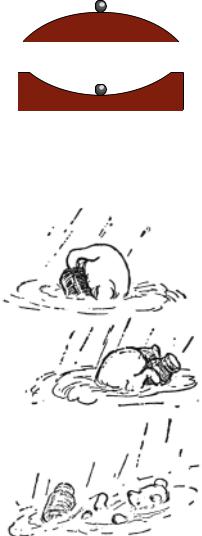
unstable
stable
Stable and unstable equilibria
A pencil balanced upright on its tip could theoretically be in equilibrium, but even if it was initially perfectly balanced, it would topple in response to the first air current or vibration from a passing truck. The pencil can be put in equilibrium, but not in stable equilibrium. The things around us that we really do see staying still are all in stable equilibrium.
Why is one equilibrium stable and another unstable? Try pushing your own nose to the left or the right. If you push it a millimeter to the left, it responds with a gentle force to the right. If you push it a centimeter to the left, its force on your finger becomes much stronger. The defining characteristic of a stable equilibrium is that the farther the object is moved away from equilibrium, the stronger the force is that tries to bring it back.
The opposite is true for an unstable equilibrium. In the top figure, the ball resting on the round hill theoretically has zero total force on it when it is exactly at the top. But in reality the total force will not be exactly zero, and the ball will begin to move off to one side. Once it has moved, the net force on the ball is greater than it was, and it accelerates more rapidly. In an unstable equilibrium, the farther the object gets from equilibrium, the stronger the force that pushes it farther from equilibrium.
Note that we are using the term “stable” in a weaker sense than in ordinary speech. A domino standing upright is stable in the sense we are using, since it will not spontaneously fall over in response to a sneeze from across the room or the vibration from a passing truck. We would only call it unstable in the technical sense if it could be toppled by any force, no matter how small. In everyday usage, of course, it would be considered unstable, since the force required to topple it is so small.
Pooh’s equilibrium is unstable.
(c) 1926 E.H. Shepard
Section 5.5 Statics |
105 |
5.6 Simple Machines: The Lever
 muscle's force
axis |
|
|
|
load's |
|||
(elbow |
|||
force |
|||
joint) |
|||
|
|
||
(a) The biceps muscle flexes the arm.
muscle's |
load's |
|
force |
||
force |
||
|
axis (elbow joint)
(b) The triceps muscle extends the arm.
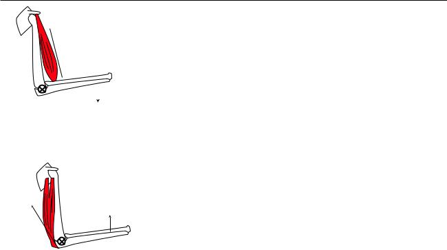
Although we have discussed some simple machines such as the pulley, without the concept of torque we were not yet ready to address the lever, which is the machine nature used in designing living things, almost to the exclusion of all others. (We can speculate what life on our planet might have been like if living things had evolved wheels, gears, pulleys, and screws.) The figures show two examples of levers within your arm. Different muscles are used to flex and extend the arm, because muscles work only by contraction.
Analyzing example (a) physically, there are two forces that do work. When we lift a load with our biceps muscle, the muscle does positive work, because it brings the bone in the forearm in the direction it is moving. The load’s force on the arm does negative work, because the arm moves in the direction opposite to the load’s force. This makes sense, because we expect our arm to do positive work on the load, so the load must do an equal amount of negative work on the arm. (If the biceps was lowering a load, the signs of the works would be reversed. Any muscle is capable of doing either positive or negative work.)
There is also a third force on the forearm: the force of the upper arm’s bone exerted on the forearm at the elbow joint (not shown with an arrow in the figure). This force does no work, because the elbow joint is not moving.
Because the elbow joint is motionless, it is natural to define our torques using the joint as the axis. The situation now becomes quite simple, because the upper arm bone’s force exerted at the elbow neither does work nor creates a torque. We can ignore it completely. In any lever there is such a point, called the fulcrum.
If we restrict ourselves to the case in which the forearm rotates with constant angular momentum, then we know that the total torque on the forearm is zero,
τmuscle + τload = 0 .
If we choose to represent counterclockwise torques as positive, then the muscle’s torque is positive, and the load’s is negative. In terms of their absolute values,
|τmuscle| = |τload| .
Assuming for simplicity that both forces act at angles of 90° with respect to the lines connecting the axis to the points at which they act, the absolute values of the torques are
rmuscleFmuscle = rloadFarm ,
where rmuscle, the distance from the elbow joint to the biceps’ point of insertion on the forearm, is only a few cm, while rload might be 30 cm or so. The force exerted by the muscle must therefore be about ten times the force
exerted by the load. We thus see that this lever is a force reducer. In general, a lever may be used either to increase or to reduce a force.
Why did our arms evolve so as to reduce force? In general, your body is built for compactness and maximum speed of motion rather than maximum force. This is the main anatomical difference between us and the
106 |
Chapter 5 Conservation of Angular Momentum |
Neanderthals (their brains covered the same range of sizes as those of modern humans), and it seems to have worked for us.
As with all machines, the lever is incapable of changing the amount of mechanical work we can do. A lever that increases force will always reduce motion, and vice versa, leaving the amount of work unchanged.
It is worth noting how simple and yet how powerful this analysis was. It was simple because we were well prepared with the concepts of torque and mechanical work. In anatomy textbooks, whose readers are assumed not to know physics, there is usually a long and complicated discussion of the different types of levers. For example, the biceps lever, (a), would be classified as a class III lever, since it has the fulcrum and load on the ends and the muscle’s force acting in the middle. The triceps, (b), is called a class I lever, because the load and muscle’s force are on the ends and the fulcrum is in the middle. How tiresome! With a firm grasp of the concept of torque, we realize that all such examples can be analyzed in much the same way. Physics is at its best when it lets us understand many apparently complicated phenomena in terms of a few simple yet powerful concepts.
Section 5.6 Simple Machines: The Lever |
107 |
5.7* Proof of Kepler’s Elliptical Orbit Law
ϕ
r
ϕ  ϕ
ϕ
r
A
Kepler determined purely empirically that the planets’ orbits were ellipses, without understanding the underlying reason in terms of physical law. Newton’s proof of this fact based on his laws of motion and law of gravity was considered his crowning achievement both by him and by his contemporaries, because it showed that the same physical laws could be used to analyze both the heavens and the earth. Newton’s proof was very lengthy, but by applying the more recent concepts of conservation of energy and angular momentum we can carry out the proof quite simply and succinctly, and without calculus.
The basic idea of the proof is that we want to describe the shape of the planet’s orbit with an equation, and then show that this equation is exactly the one that represents an ellipse. Newton’s original proof had to be very complicated because it was based directly on his laws of motion, which include time as a variable. To make any statement about the shape of the orbit, he had to eliminate time from his equations, leaving only space variables. But conservation laws tell us that certain things don’t change over time, so they have already had time eliminated from them.
There are many ways of representing a curve by an equation, of which the most familiar is y=ax+b for a line in two dimensions. It would be perfectly possible to describe a planet’s orbit using an x-y equation like this, but remember that we are applying conservation of angular momentum, and the space variables that occur in the equation for angular momentum
are the distance from the axis, r, and the angle between the velocity vector and the r vector, which we will call ϕ. The planet will have ϕ=90° when it is
moving perpendicular to the r vector, i.e. at the moments when it is at its smallest or greatest distances from the sun. When ϕ is less than 90° the planet is approaching the sun, and when it is greater than 90° it is receding from it. Describing a curve with an r-ϕ equation is like telling a driver in a parking lot a certain rule for what direction to steer based on the distance from a certain streetlight in the middle of the lot.
The proof is broken into the three parts for easier digestion. The first part is a simple and intuitively reasonable geometrical fact about ellipses, whose proof we relegate to the caption of a figure; you will not be missing much if you merely absorb the result without reading the proof.
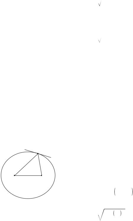
(1) If we use one of the two foci of an ellipse as an axis for defining the variables r and ϕ, then the angle between the tangent line and the line drawn to the other focus is the same as ϕ, i.e. the two angles labeled ϕ in the figure are in fact equal.
Proof that the two angles labeled ϕ are in fact equal: The definition of an ellipse is that the sum of the distances from the two foci stays constant. If we move a small distance
 along the ellipse, then one distance shrinks by an amount
  cos ϕ1 , while the other grows by
  cos ϕ2 . These are equal, so ϕ1=ϕ2.
108 |
Chapter 5 Conservation of Angular Momentum |
ϕα ϕ |
r s
d
The other two parts form the meat of our proof. We state the results first and then prove them.
(2) A planet, moving under the influence of the sun’s gravity with less then the energy required to escape, obeys an equation of the form
sin ϕ = |
|
1 |
|
|
, |
|
|
|
|
||
– pr 2 |
|
||||
|
|
+ qr |
|||
where p and q are constants that depend on the planet’s energy and angular momentum and p is greater than zero.
(3) A curve is an ellipse if and only if its r-ϕ equation is of the form
sin ϕ = |
|
1 |
|
|
, |
|
|
|
|
||
– pr 2 |
|
||||
|
|
+ qr |
|||
where p and q are constants that depend on the size and shape of the ellipse and p is greater than zero.
Proof of part (2)
The component of the planet’s velocity vector that is perpendicular to the r vector is v =v sin ϕ, so conservation of angular momentum tells us that L = mrv sin ϕ is a constant. Since the planet’s mass is a constant, this is the same as the condition
rv sin ϕ = constant .
Conservation of energy gives
1 |
2 |
– G |
Mm |
= constant . |
2mv |
|
r |
We solve the first equation for v and plug into the second equation to eliminate v. Straightforward algebra then leads to the equation claimed above, with the constant p being positive because of our assumption that the planet’s energy is insufficient to escape from the sun, i.e. its total energy is negative.
Proof of part (3)
We define the quantities α, d, and s as shown in the figure. The law of cosines gives
d 2 = r 2 + s 2 – 2rs cos α .
Using α=180°–2ϕ and the trigonometric identities cos (180°–x)=–cos x and cos 2x = 1–2 sin2x, we can rewrite this as
d 2 = r 2 + s 2 + 2rs 1 – sin2ϕ |
. |
Straightforward algebra transforms this into
sin ϕ = |
d 2 + r+s |
2 |
. |
2rs |
|
||
|
|
|
Since r+s is constant, the top of the fraction is constant, and the denominator can be rewritten as 2rs=2r(constant-r), which is equivalent to the desired form.
Section 5.7* Proof of Kepler’s Elliptical Orbit Law |
109 |

Summary
Selected Vocabulary
angular momentum .......... |
a measure of rotational motion; a conserved quantity for a closed |
|
system |
axis .................................. |
An arbitrarily chosen point used in the definition of angular momentum. |
|
Any object whose direction changes relative to the axis is considered to |
|
have angular momentum. No matter what axis is chosen, the angular |
|
momentum of a closed system is conserved. |
torque ............................... |
the rate of change of angular momentum; a numerical measure of a |
|
force’s ability to twist on an object |
equilibrium ....................... |
a state in which an object’s momentum and angular momentum are |
|
constant |
stable equilibrium ............. |
one in which a force always acts to bring the object back to a certain |
|
point |
unstable equilibrium ......... |
one in which any deviation of the object from its equilibrium position |
|
results in a force pushing it even farther away |
Notation |
|
L ....................................... |
angular momentum |
τ ............................................ |
torque |
T ....................................... |
the time required for a rigidly rotating body to complete one rotation |
Standard Terminology and Notation Not Used in This Book |
|
period ............................... |
a name for the variable T defined above |
moment of inertia, I .......... |
the proportionality constant in the equation L = 2πI / T |
Summary
Angular momentum is a measure of rotational motion which is conserved for a closed system. This book only discusses angular momentum for rotation of material objects in two dimensions. Not all rotation is rigid like that of a wheel or a spinning top. An example of nonrigid rotation is a cyclone, in which the inner parts take less time to complete a revolution than the outer parts. In order to define a measure of rotational motion general enough to include nonrigid rotation, we define the angular momentum of a system by dividing it up into small parts, and adding up all the angular momenta of the small parts, which we think of as tiny particles. We arbitrarily choose some point in space, the axis, and we say that anything that changes its direction relative to that point possesses angular momentum. The angular momentum of a single particle is
L = mv r ,
where v is the component of its velocity perpendicular to the line joining it to the axis, and r is its distance from the axis. Positive and negative signs of angular momentum are used to indicate clockwise and counterclockwise rotation.
The choice of axis theorem states that any axis may be used for defining angular momentum. If a system’s angular momentum is constant for one choice of axis, then it is also constant for any other choice of axis.
The spin theorem states that an object's angular momentum with respect to some outside axis A can be found by adding up two parts:
(1)The first part is the object's angular momentum found by using its own center of mass as the axis, i.e. the angular momentum the object has because it is spinning.
(2)The other part equals the angular momentum that the object would have with respect to the axis A if it had all its mass concentrated at and moving with its center of mass.
Torque is the rate of change of angular momentum. The torque a force can produce is a measure of its ability to twist on an object. The relationship between force and torque is
|τ| = r |F | ,
where r is the distance from the axis to the point where the force is applied, and F is the component of the force perpendicular to the line connecting the axis to the point of application. Statics problems can be solved by setting the total force and total torque on an object equal to zero and solving for the unknowns.
110 |
Chapter 5 Conservation of Angular Momentum |