

MIPS_primery_zadach / dandamudi05gtr guide risc processors programmers engineers
.pdf72 |
Guide to RISC Processors |
As with the parameter passing, we have to use the stack to return the remaining return values.
Stack Implementation
We briefly describe the SPARC stack implementation. As in the MIPS architecture, the stack grows downward (i.e., from a higher memory address to a lower address). However, there are no explicit stack push and pop instructions. Instead, these instructions can be synthesized by manipulating the stack pointer sp. For example, to push or pop the contents of i0, we can use the following code.
Push operation |
Pop operation |
||
sub |
%sp,4,%sp |
add |
%sp,4,%sp |
st |
%i0,[%sp] |
ld |
[%sp],%i0 |
To allocate an N -byte stack frame, we can use
sub %sp,N ,%sp
Window Management
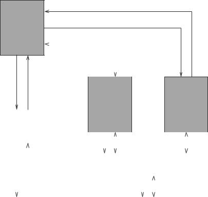
SPARC processors can have up to 32 register windows. The number of windows available on a specific implementation is given by NWINDOWS. Note that NWINDOWS can range from 3 to 32. As noted, the Current Window Pointer (CWP) points to the current register set. These window sets are organized as a circular buffer (see Figure 5.4). Thus, the CWP arithmetic can be done modulo NWINDOWS.
With each procedure call, a new register window is assigned. This is done by the save instruction. This instruction can also allocate space on the stack for the stack frame. The save instruction
save %sp,−N ,%sp
slides the register window by incrementing CWP (mod NWINDOWS) and allocates N bytes of stack space. If no errors occur, save acts as the add instruction does. Thus, by specifying sp and a negative N value, it allocates N bytes of stack space. As in the add instruction, the second operand can also be a register.
The restore instruction restores the register window saved by the last save instruction. Its format is similar to that of the save. It also performs addition on its operands as does the save instruction. A trivial restore pseudoinstruction is defined as
restore %g0,%g0,%g0
A typical procedure looks like

Chapter 5 • SPARC Architecture |
|
73 |
||
|
|
W1 |
|
|
|
|
LOCALs |
OUTs |
|
CWP = 0 |
INs |
|
|
|
|
|
|
INs |
|
|
|
OUTs |
LOCALs |
INs |
|
|
|
|
|
|
|
|
W2 |
|
|
LOCALs |
OUTs |
|
|
|
|
W0 |
|
W3 |
OUTs |
|
|
|
|
INs |
|
|
LOCALs |
|
|
|
|
|
|
|
|
save |
restore |
|
LOCALs |
|
|
INs |
OUTs |
|
|
|
||
W7 |
|
|
W4 |
|
|
OUTs |
W6 |
LOCALs |
|
|
|
|
|
|
INs |
LOCALs |
OUTs |
|
|
|
|
|
|
|
INs
INs
OUTs LOCALs
W5
Figure 5.4 The register windows are organized as a circular buffer.
proc-name:
save %sp,−N ,%sp
. . .
procedure body
. . .
ret
restore
Note that the restore instruction is executed in the delay slot. Because the restore does not add N to sp, you might be wondering about how the stack allocation is released. To understand this, we should look at the way the save instruction performs the add operation on its operands. For this add operation, save uses the old window for the two source operands and stores the result in the new window. In our example, it adds −N to the sp value from the previous window and stores the result in the new window’s sp register. Thus, when we restore the previous window, we automatically see the previous sp value.
A leaf procedure does not use a new register window. It uses the registers from the caller’s window. A typical leaf procedure looks like

74 |
Guide to RISC Processors |
%fp |
|
Previous stack frame |
|
|
|
|
|
Space for local variables, |
%fp offset |
|
temporaries, etc. |
|
Space for remaining |
|
|
|
|
%sp + 184 |
|
arguments (7, 8, . . .) |
|
Argument 6 |
|
|
|
|
|
|
Argument 5 |
|
|
Argument 4 |
|
|
Argument 3 |
|
|
Argument 2 |
%sp + 136 |
|
Argument 1 |
|
||
%sp + 128 |
|
‘‘Hidden’’ parameter |
|
||
|
|
Space for saved IN and |
|
|
LOCAL registers |
%sp |
|
(16 extended words) |
|
|
|
|
Figure 5.5 SPARC’s stack frame. |
|
proc-name:
. . .
procedure body
. . . |
|
retl |
/* use retl, not ret */ |
Minimum stack frame
What happens if the save instruction cannot get a new window of registers? For this reason, the stack frame maintains space for the in, local, and six arguments. In addition, there is a “hidden parameter” to return a structure pointer. Thus, a minimum of (16 + 1 + 6) * 8 = 184 bytes of stack frame is needed. Additional space may be needed for storing temporaries, more arguments, and so on, as shown in Figure 5.5.
We give an example procedure to illustrate how these instructions are used. We use the following C code consisting of three procedures.
. . .
i = condSum (1, 2, 3, 4)
. . .
int condSum(int a, int b, int c, int d)
{
Chapter 5 • SPARC Architecture |
75 |
int t1;
t1 = a; if (a < b)
t1 = b; return(sum(t1,c,d));
}
int sum(int x, int y, int z)
{
return(x+y+z);
}
The corresponding SPARC assembly code is shown in three procedures. In the main procedure, the four arguments of condSum are moved to the first four out registers: o0 through o3.
|
. . . |
|
mov |
1,%o0 |
; first argument |
mov |
2,%o1 |
; second argument |
mov |
3,%o2 |
; third argument |
call |
condSum |
|
mov |
4,%o3 |
; fourth argument in delay slot |
;condSum returns result in %o0. When condSum returns,
;the following instruction is executed
mov |
%o0,%l0 |
; return result moved to %l0 |
|
. . . |
|
Because the call is a delayed instruction, we use the delay slot to move the fourth argument to o3. Note that the condSum call should return to the instruction
mov %o0,%l0
This is the reason for adding 8 to the return address. This procedure returns the sum in the o0 register. The above mov instruction copies this value to the l0 local register.
The first instruction in the condSum procedure is the save instruction. As we have discussed, it allocates a new register window by incrementing the CWP. We also allocate 184 bytes of stack frame, which is the minimum size. The next four instructions select the minimum of the first two arguments. Note that the out registers of the previous window are referred to as in registers in the current window. We move the three arguments to out registers to pass them on to the sum procedure. When sum returns the total, this value is moved from o0 to i0 so that the result is available in o0 in the main procedure.

76 |
|
Guide to RISC Processors |
|
;*********** condSum procedure ********** |
|||
condSum: |
|
|
|
save |
%sp,-184,%sp; allocate min. stack frame |
||
mov |
%i0, %o0 |
|
|
cmp |
%i1, %i0 |
; if %i1 is less/equal, |
|
ble |
skip |
; skip the following mov |
|
mov |
%i1, %o0 |
|
|
skip: |
|
|
|
mov |
%i2, %o1 |
; second argument |
|
call |
sum |
|
|
mov |
%i3, %o2 |
; third argument in delay slot |
|
mov |
%o0, %i0 |
; move the result returned by sum to %o0 |
|
ret |
|
|
|
restore |
|
; trivial restore in delay slot of ret |
|
;******* end of condSum procedure *******
The sum procedure is a leaf procedure as it does not call any other procedure. We can optimize a leaf procedure by not requesting a new window; instead it uses the registers from the caller’s window. Thus, there is no need for the save and restore instructions. The only instruction that needs special care is the return: we have to use retl rather than the ret instruction.
;*********** sum procedure ***********
sum:
add |
%o0, %o1, %o0 ; |
first addition |
retl |
; |
leaf procedure, use retl |
add |
%o0, %o2, %o0 ; |
final add in delay slot |
; result returned in %o0
;******* end of sum procedure ********
Summary
We have briefly presented the architecture and instruction set of the SPARC. A user program is provided with 32 general-purpose registers, which are organized into four register sets: in, out, local, and global. It supports a register window mechanism that facilitates efficient parameter passing in procedure calls. We see a similar mechanism in Chapter 7.
The SPARC architecture supports two basic addressing modes. One is similar to the addressing mode we have seen in the last chapter. The other computes the effective address as the sum of the contents of two registers. As does the MIPS architecture, SPARC also uses 32 bits to encode instructions. After reading details about the other architectures, you will notice that it supports a fairly standard set of instructions.
A notable difference from other processors is that it is a specification at the ISA level that is available to chip manufacturers, which means several implementations are possible. For example, an implementation can choose to have a number of register windows be-
Chapter 5 • SPARC Architecture |
77 |
tween 3 and 32. Furthermore, there are also several instructions that have implementationdefined semantics. If you are interested in more details, several reference documents are available at the SPARC Web site.
Web Resources
Full specifications and other reference material on the SPARC architecture are available from www.sparc.org. Sun also maintains information on their SPARC processors at www.sun.com/microelectronics/sparc.

6
PowerPC Architecture
This chapter gives details on the PowerPC architecture. We start the chapter with an overview and a brief history of the PowerPC architecture. We then give its register set details and the addressing modes supported. As does the SPARC, PowerPC supports two addressing modes. However, PowerPC also supports update versions of these addressing modes. The update versions, for example, are useful in providing “regular” access to arrays. Unlike the MIPS architecture, PowerPC supports a variety of instruction formats. The instruction set details are presented next. After reading this section, you will notice that the PowerPC branch instructions are flexible and can take branch prediction hints from the compiler. We conclude the chapter with a summary.
Introduction
The PowerPC defines a 64-bit architecture that can operate in two modes: 64-bit and 32bit mode. It supports dynamic switching between these two modes. In the 32-bit mode, a 64-bit PowerPC processor can execute 32-bit application binaries.
Here is a short history of the PowerPC architecture [9]. IBM developed many of the concepts in 1975 for a prototype system. An unsuccessful commercial version of this prototype was introduced around 1986. Four years later, IBM introduced the RS/6000 family of processors based on their POWER architecture. In early 1991, a group from Motorola, IBM, and Apple began work on the PowerPC architecture using the IBM POWER architecture as the base. The PowerPC includes many of the POWER instructions. PowerPC dropped some of the POWER instructions, but these were not frequently used. The first implementation of the PowerPC architecture, the PowerPC 601, implemented all but two POWER instructions so that POWER applications run on the PowerPC.
The PowerPC family of processors is available in both 32and 64-bit implementations. Here we discuss the 64-bit implementation. As are the MIPS and SPARC, the PowerPC architecture is based on the load/store architecture. It satisfies many of the RISC characteristics we mentioned in Chapter 2.
79
80 |
Guide to RISC Processors |
Status
BPU
FXU and FPU Instructions
Branch |
|
|
|
|
|
|
|
|
|
Processing |
Status |
|
|
|
Unit |
|
|
||
|
|
|
|
|
|
|
|
|
|
|
|
|
|
|
Address |
|
|
Instruction |
FXU |
|
FPU |
||||||||||
|
|
|
|
|
|
|
|
|
||||||||
|
|
|
|
|
|
Fixed−point |
|
Floating−point |
||||||||
|
|
|
|
|
|
Processing |
|
Processing |
||||||||
|
|
|
|
|
|
|
||||||||||
|
Instruction |
|
Unit |
|
Unit |
|||||||||||
|
|
Cache |
|
|
|
|
|
|
|
|
|
|
|
|
||
|
|
|
|
|
Address |
|
|
Data |
|
|
Data |
|||||
|
|
|
|
|
|
|||||||||||
|
|
|
|
|
|
|
|
|
|
|
|
|
|
|
|
|
Address |
|
|
Instruction |
|
|
|
|
Data Cache |
|
|||||||
|
|
|
|
|
|
|
|
|
|
|
|
|||||
|
|
|
|
|
|
|
|
|
|
|
|
|
|
|
||
|
|
|
|
|
|
|
|
|
|
Address |
|
Data |
||||
|
|
|
|
|
|
|
|
|
|
|
|
|
||||
|
|
|
|
|
Main Memory |
|
|
|
|
|||||||
|
|
|
|
|
|
|
|
|
|
|
|
|
|
|
|
|
Figure 6.1 High-level view of the PowerPC architecture.
A high-level view of the PowerPC architecture is shown in Figure 6.1. It consists of three functional units to facilitate superscalar implementation in which multiple functional units concurrently work on independent instructions.
•Branch Processing Unit: The BPU is responsible for fetching instructions and executing branch and related instructions. In addition, the BPU also dispatches instructions for the fixed-point and floating-point units as shown in Figure 6.1.
•Fixed-point Processing Unit: The FXU executes the fixed-point instructions, which we discuss later in this chapter. It also computes the addresses of store and load instructions for the floating-point unit.
•Floating-point Processing Unit: The FPU executes the floating-point instructions, which operate on floating-point numbers that conform to the IEEE 754 standard (see our discussion of this format in Appendix A). It is also responsible for managing the

Chapter 6 • PowerPC Architecture |
81 |
floating-point loads and stores. Note that the fixed-point unit generates addresses for these operations.
The PowerPC instructions can be divided into three classes, depending on which unit executes them: branch instructions, fixed-point instructions, and floating-point instructions. Fixed-point instructions operate on byte (8 bits), halfword (16 bits), word (32 bits), and doubleword (64 bits) operands. Floating-point instructions operate on singleprecision and double-precision floating-point numbers.
In the remainder of the chapter, we discuss the PowerPC register set, its addressing modes, and fixed-point and branch instructions. For the sake of brevity, we do not discuss its floating-point instructions (see [23] for details on these instructions).
Register Set
The PowerPC has 32 general-purpose registers for integer data (GPR0 to GPR31). An equal number of registers are available for floating-point data (FPR0 to FPR31), as shown in Figure 6.2. The integer registers (GPRs) as well as the floating-point registers (FPRs) are 64 bits wide. In addition, it has the following special registers: CR, LR, CTR, FPSCR, and XER. The register set can be partitioned into three groups, each group associated with a processing unit:
•Branch processing unit uses the following three special registers: Condition Register (CR), Link Register (LR), and CounT Register (CTR). The last two registers are 64 bits long and the CR is 32 bits long.
•Fixed-point processing unit uses the 32 general-purpose registers GPR0 to GPR31 and the fiXed-point Exception Register (XER).
•Floating-point processing unit uses the 32 floating-point registers FPR0 to FPR31 and the Floating-point Status and Control Register (FPSCR).
The FPSCR register consists of two types of bits: bits 0–23 are used to record the status of the floating-point operations. The remaining bits are control bits that record any exceptions generated by floating-point operations. For example, bit 23 records the invalid operation exception which occurs when an operand is invalid for the specified floatingpoint operation. The floating-point divide-by-zero exception is captured in bit 5. The functionality of the remaining four special registers is described next.
Condition Register (CR)
The 32-bit register is divided into eight CR fields of 4 bits each (CR0 to CR7). CR0 is used to capture the result of a fixed-point instruction. The four CR0 bits are interpreted as follows [23].
82 |
|
|
|
Guide to RISC Processors |
||||
|
General−purpose |
|
Floating−point |
|
|
|
|
|
|
registers |
|
registers |
|
Condition register |
XER register |
||
|
|
|
|
|
|
|
|
|
|
GPR0 (64) |
|
FPR0 (64) |
|
CR (32) |
|
XER (64) |
|
|
|
|
|
|
|
|
|
|
|
GPR1 (64) |
|
FPR1 (64) |
Floating−point status |
Link register |
|||
|
. |
|
. |
|||||
|
|
|
and control register |
|
|
|||
|
|
|
LR (64) |
|
||||
|
. |
|
. |
|
|
|
|
|
|
|
|
|
|
|
|
||
|
. |
|
. |
|
FPSCR (32) |
|
Count register |
|
|
|
|
|
|
|
|
||
|
GPR31 (64) |
|
FPR31 (64) |
|
|
|
CTR (64) |
|
|
|
|
|
|
|
|
|
|
Figure 6.2 PowerPC registers: general-purpose, link, XER, and count registers are 32bits long in 32-bit implementations and 64-bits long in 64-bit implementations. The other registers are of fixed size independent of the implementation.
Bit Description
0Negative (LT)
The result is negative.
1Positive (GT)
The result is positive.
2Zero (EQ)
The result is zero.
3Summary overflow (SO)
This is a copy of the SO bit from XER register (discussed later).
The first bit can be interpreted as representing the “less than” (LT) relationship. Similarly, the second and third bits represent “greater than” (GT) and “equal to” (EQ) relationships, respectively.
The CR1 field is used to capture floating-point exception status. These four bits are a copy of the least significant four bits of the FPSCR register. Because we do not discuss the floating-point unit details here, we skip the interpretation of these four bits (see [23] for details).
The remaining CR fields can be used for either integer or floating-point instructions to capture integer or floating-point LT, GT, EQ, and SO conditions. Instructions are available to perform logical operations on individual CR bits. Branch instructions are available to test a specific CR field bit. These instructions can specify the CR field that should be used.
Link Register (LR)
The 64-bit link register is used to store the return address in a procedure call. Procedure calls are implemented by branch (bl/bla) or conditional branch (bc/bca) instructions. For these instructions, the LR register receives the effective address of the instruction following the branch instruction.