

MIPS_primery_zadach / dandamudi05gtr guide risc processors programmers engineers
.pdfChapter 8 • ARM Architecture |
143 |
|
; loop count is in R0 |
|
|
mov |
R0,#50 |
; init loop count to 50 |
loop |
|
|
|
. . . |
|
|
. . . |
|
subs |
R0,R0,#1 |
; decrement loop count |
bne |
loop |
; if R0 != 0, loop back |
The last instruction bne can be considered as “branch on not equal to zero” as it branches to the target if the zero flag is 0.
Procedures
The branch instruction of the last section can be modified to invoke a procedure. A procedure call is like a branch with the provision that it remembers the return address. Thus, if we can make the branch instruction store the return address, it can be used as a procedure call instruction. This is what the l field does:
bl{cond} target_address
This branch and link instruction places the return address in the link register LR, which is R14, before transferring control to the target. The return address stored is the address of the instruction following the bl instruction. For example, if we want to invoke the findMin procedure, we do so by
bl findMin
How do we return from the procedure? It is simple: all we have to do is to copy the return address from the LR to the PC. We can do this by using the following move instruction.
mov PC,LR
Here is an example that shows the structure of an ARM procedure:
;ARM code to find minimum of two signed integers
;The two input values are in R0 and R1
;The minimum is returned in R2
findMin |
|
|
|
|
cmp |
R1,R0 |
|
|
|
movge |
R2,R0 |
; R1 |
>= R0? Min = R0 |
|
movlt |
R2,R1 |
; |
R1 |
< R0? Min = R1 |
mov |
PC,LR |
; |
return |
|
This procedure receives two signed numbers in R0 and R1 and returns the minimum of these two values in R2.
144 |
Guide to RISC Processors |
Stack Operations
As in the MIPS, there is no special stack pointer register in the ARM architecture. By convention, register R13 is used as the stack pointer. There is another similarity with MIPS: ARM does not provide any special instructions to manipulate the stack. That is, there are no push and pop instructions. We have to implement these stack operations by using load and store instructions. This means we have complete freedom as to how the stack should behave. A stack implementation is characterized by two attributes:
•Where the stack pointer points
–Full stack: The stack pointer points to the last full location;
–Empty stack: The stack pointer points to the first empty location.
•How the stack grows
–Descending stack: The stack grows downward (i.e., toward lower memory addresses);
–Ascending stack: The stack grows upward (i.e., toward higher memory addresses).
These two attributes define the four types of stacks:
•Full Descending stack (mnemonic fd);
•Full Ascending stack (mnemonic fa);
•Empty Descending stack (mnemonic ed);
•Empty Ascending stack (mnemonic ea).
These mnemonics can be used in ldm and stm instructions to manipulate the stack. For example, we can use instructions such as ldmfd, stmfd, and so on. Most implementations, including MIPS and SPARC, prefer descending stacks for reasons discussed in Chapter 4 (page 53). Furthermore, the stack pointer points to the last item pushed on to the stack.
Using the ldmfd and stmfd instructions, we can write procedure entry and exit code as follows.
procName
stmfd R13!,{R4-R12,LR} ; save registers and ; return address
. . .
<procedure body>
. . .
ldmfd R13!,{R4-R12,PC} ; restore registers and ; return address to PC

Chapter 8 • ARM Architecture |
145 |
This code assumes that we do not have to preserve the first four registers as they are often used to pass parameters. Furthermore, we assume that the stack pointer (R13) points to a full descending stack. The stmfd instruction stores registers R4 to R12 and LR on the stack before executing the procedure body. Notice that we use R13! (i.e., the write-back option) so that the stack pointer is updated to point to the last full location of the stack. Before returning from the procedure, we use the ldmfd instruction to restore the registers and to store the return address in the PC. Because we store the return address in the PC we do not need a separate return from the procedure.
Summary
The ARM architecture is remarkably different from the other architectures we have seen in this part. It shares some features with the Itanium architecture. One feature of the ARM instruction set that sets it apart is that its instructions are executed conditionally. If the specified condition is not true, the instruction acts as a nop. Although Itanium also uses conditional instruction execution, the ARM uses a 4-bit condition code as opposed to the predicate bits of Itanium. Another interesting feature of ARM is that arithmetic and logical instructions can pre-process (shift/rotate) one of the input operands before operating on it.
At the beginning of this chapter, we mentioned that Thumb instructions are 16 bits long. To achieve this reduction from the 32-bit ARM instructions, several significant changes have been made. These include:
•The 4-bit cond field is eliminated. As a result, most Thumb instructions are executed unconditionally. In contrast, ARM instructions are executed conditionally.
•Most Thumb arithmetic and logical instructions use the 2-address format. In this format, as discussed in Chapter 2, the destination register also supplies a source operand.
Even though the ARM is a RISC architecture, it does not strictly follow the RISC principles as does the MIPS. For example, some of the ARM instructions such as ldm and stm are not simple instructions. In addition, it provides a large number of addressing modes and uses a somewhat complex instruction format. However, having looked at five different RISC designs, you will also see a lot of commonality among these architectures and the RISC principles given in Chapter 3. In the next part, we take a detailed look at the MIPS assembly language.
Web Resources
Most of the ARM documentation is available from their Web site www.arm.com. The ARM Architecture Reference Manual is published by Addison-Wesley [1]. The reference manual is also distributed by ARM on their documentation CD. Unfortunately, this information is not available from their Web site; you have to request this CD from ARM.
PART III
MIPS Assembly Language

9
SPIM Simulator
and Debugger
SPIM is a simulator that runs MIPS 2000 programs. SPIM supports various platforms and can be downloaded from the Web. SPIM also contains a simple debugger. In this chapter, we give details on how you can download and use the SPIM simulator. We start with an introduction to the SPIM simulator. The following section gives details about SPIM settings. These settings determine how the simulator loads and runs your programs. We specify the settings you should use in order to run the example MIPS programs given in later chapters. Details about loading and running MIPS assembly language programs are discussed in the next section. This section also presents the debugging facilities provided by SPIM. We conclude the chapter with a summary.
Introduction
This chapter describes the SPIM simulator, which was developed by Professor James Larus when he was at the Computer Science Department of the University of Wisconsin, Madison. This simulator executes the programs written for the MIPS R2000/R3000 processors. This is a two-in-one product: it contains a simulator to run the MIPS programs as well as a debugger.
SPIM runs on a variety of platforms including UNIX, Linux, Windows, and DOS. In this chapter, we provide details on the Windows version of SPIM called PCSpim. The SPIM simulator can be downloaded from
http://www.cs.wisc.edu/˜larus/spim.html
This page also gives information on SPIM documentation. Although SPIM is available
149
150 |
Guide to RISC Processors |
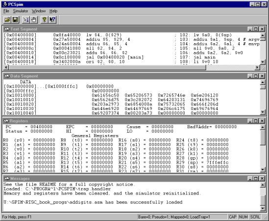
Figure 9.1 SPIM windows.
from this site at the time of this writing, use a good search engine to locate the URL if it is not available from this URL. Also, you can check this book’s homepage, which provides a link to the SPIM simulator that is updated periodically.
Figure 9.1 shows the PCSpim interface. As shown in this figure, PCSpim provides a menu bar and a toolbar at the top and a status bar at the bottom of the screen. The middle area displays four windows, as discussed next.
•Menu Bar: The menu bar provides the following commands for the simulator operation.
–File: The File menu allows you select file operations. You can open a MIPS assembly language source file using open... or save a log file of the current simulator state. In addition, you can quit PCSpim by selecting the Exit command. Of course, you can also quit PCSpim by closing the window.
Chapter 9 • SPIM Simulator and Debugger |
151 |
–Simulator: This menu provides several commands to run and debug a program. We discuss these commands later in this chapter. This menu also allows you to select the simulator settings. When the Settings... command is selected, it opens a setting window to set the simulator settings, which are discussed in the next section.
–Windows: This menu allows you to control the presentation and navigation of windows. For example, in Figure 9.1, we have tiled windows to show the four windows: Text Segment, Data Segment, Register, and Messages. In addition, you can also elect to hide or display the toolbar and status bar. The console window pops up when your program needs to read/write data to the terminal. It disappears after the program has terminated. When you want to see your program’s input and output, you can activate this window by selecting the Console window command.
–Help: This menu allows you to obtain online help on PCSpim.
•Toolbar: The toolbar provides mouse buttons to open and close a MIPS assembly language source file, to run and insert breakpoints, and to get help.
•Window Display Section: This section displays four windows: Data Segment, Text Segment, Messages, and Register.
–Data Segment Window: This window shows the data and stack contents of your program. Each line consists of an address (in square brackets) and the corresponding contents in hexadecimal notation. If a block of memory contains the same constant, an address range is specified as shown on the first line of the Data Segment in Figure 9.1.
–Text Segment Window: This window shows the instructions from your program as well as the system code loaded by PCSpim. The leftmost hex number in square brackets is the address of the instruction. The second hex number is the machine instruction encoding of the instruction. Next to it is the instruction mnemonic, which is a processor instruction. What you see after the semicolon is the source code line including any comments you have placed. This display is useful to see how the pseudoinstructions of the assembler are translated into the processor instructions. For example, the last line in the Text Segment of Figure 9.1 shows that the pseudoinstruction
li $vi,10
is translated as
ori $2,$0,10
–Registers: This window shows the contents of the general and floating-point registers. The contents are displayed in either decimal or hex notation, depending on the settings used (discussed in the next section).
–Messages: This window is used by PCSpim to display error messages.
152 |
Guide to RISC Processors |
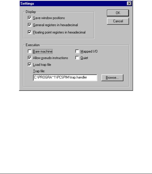
Figure 9.2 SPIM settings window.
•Status Bar: The status bar at the bottom of the PCSpim window presents three pieces of information:
–The left area is used to give information about the menu items and toolbar buttons. For example, when the mouse arrow is on the open file icon (first button) on the toolbar, this area displays the “Open an assembly file” message.
–The middle area shows the current simulator settings. Simulator settings are described in the next section.
–The right area is used to display if the Caps Lock key (CAP), Num Lock key (NUM), and Scroll Lock key (SCRL) are latched down.
Simulator Settings
PCSpim settings can be viewed by selecting the Settings command under the Simulator menu. This opens a setting window as shown in Figure 9.2. PCSpim uses these settings to determine how to load and run your MIPS assembly language program. An incorrect setting may cause errors. The settings are divided into two groups: Display and Execution. The Display settings determine whether the window positions are saved and how the contents of the registers are displayed. When Save window positions is selected, PCSpim will remember the position of its windows when you exit and restore them when

Chapter 9 • SPIM Simulator and Debugger |
153 |
you run PCSpim later. If you select the register display option, contents of the general and floating-point registers are displayed in hexadecimal notation. Otherwise, register contents are displayed as decimal numbers.
The Execution part of the settings shown in Figure 9.2 determines how your program is executed.
•Bare Machine: If selected, SPIM simulates the bare MIPS machine. This means that both pseudoinstructions and additional addressing modes, which are provided by the assembler, are not allowed. Later chapters give details on the assemblersupported pseudoinstructions and addressing modes. Because the example MIPS programs presented in later chapters use these additional features of the assembler, this option should not be selected to run our example programs.
•Allow Pseudoinstructions: This setting determines whether the pseudoinstructions are allowed in the source code. You should select this option as our example programs use pseudoinstructions.
•Mapped I/O: If this setting is selected, SPIM enables the memory-mapped I/O facility. When this setting is selected, you cannot use SPIM system calls, described in Chapter 10 on page 161, to read from the terminal. Thus, this setting should not be selected to run our MIPS programs.
•Quiet: If this setting is selected, PCSpim will print a message when an exception occurs.
•Load Trap File: Selecting this setting causes PCSpim to load the standard exception handler and startup code. The trap handler can be selected by using the Browse button. When loaded, the startup code in the trap file invokes the main routine. In this case, we can label the first executable statement in our program as main. If the trap file is not selected, PCSpim starts execution from the statement labeled
start. Our example programs are written with the assumption that the trap file is loaded (we use the main label). If you decide not to use the trap file, you have to change the label to start to run the programs. If the trap file is loaded, PCSpim transfers control to location 0x80000080 when an exception occurs. This location must contain an exception handler.
Running a Program
Before executing a program, you need to load the program you want to run. This can be done either by selecting the Open File button from the Toolbar or from the File menu. This command lets you browse for your assembly file by opening a dialog box. After opening the file, you can issue the Run command either from the Toolbar or from the Simulator menu to execute the program.
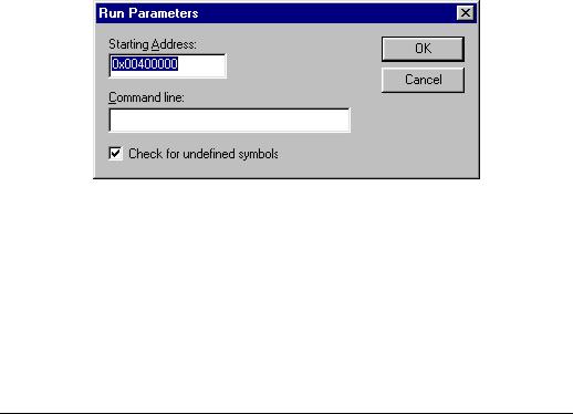
The Run command pops the Run window shown in Figure 9.3. It automatically fills the start address. For our example programs, you don’t have to change this value. If desired, the command line options can be entered in this window. Command line options
154 |
Guide to RISC Processors |
Figure 9.3 SPIM Run window.
that you can specify include the settings we discussed in the last section. For example, you enter -bare to simulate a bare MIPS machine, -asm to simulate the virtual MIPS machine provided by the assembler, and so on. The SPIM documentation contains a full list of acceptable command line options. If you have set up the settings as discussed in the last section, you don’t have to enter any command line option to run our example MIPS programs.
Debugging
SPIM provides the standard facilities to debug programs. As you know, single-stepping and breakpoints are the two most popular techniques used to debug programs. As part of debugging, you often need to change the values in a register set or memory locations. As do the other debuggers you are familiar with, SPIM provides commands to alter the value of a register or memory location. All debug commands are available under the Simulator menu as shown in Figure 9.4. These commands are briefly explained next.
•Clear Registers: This command clears all registers (i.e., the values of all registers are set to zero).
•Reinitialize: It clears all the registers and memory and restarts the simulator.
•Reload: This command reinitializes the simulator and reloads the current assembler file for execution.
•Go: You can issue this command to run the current program. Program execution continues until a breakpoint is encountered. We have discussed the Run command before. You can also use the F5 key to execute your program.
•Break/Continue: This can be used to toggle between break and continue. If the program is running, execution is paused. On the other hand, if the execution is paused, it continues execution.