

MIPS_primery_zadach / dandamudi05gtr guide risc processors programmers engineers
.pdf52 |
|
|
|
|
|
|
|
|
Guide to RISC Processors |
||||
31 |
26 |
25 |
21 |
20 |
16 |
15 |
|
|
|
|
0 |
|
|
|
|
|
|
|
|
|
|
|
|
|
|
|
|
|
|
op |
|
rs |
rt |
|
|
16−bit immediate value |
|
|
|||
|
|
|
|
|
|
|
|
|
|
|
|
||
|
|
|
|
|
I−Type (Immediate) |
|
|
|
|
|
|||
31 |
26 |
25 |
|
|
|
|
|
|
|
|
0 |
|
|
|
|
|
|
|
|
|
|
|
|
|
|
|
|
|
|
op |
|
|
|
|
26−bit target |
|
|
|
|
||
|
|
|
|
|
|
|
|
|
|
|
|
|
|
|
|
|
|
|
J−Type (Jump) |
|
|
|
|
|
|
||
31 |
26 |
25 |
21 |
20 |
16 |
15 |
10 |
11 |
6 |
5 |
0 |
|
|
|
|
|
|
|
|
|
|
|
|
|
|
|
|
|
|
op |
|
rs |
rt |
|
rd |
|
sa |
|
function |
|
|
|
|
|
|
|
|
|
|
|
|
|
|
|
|
R−Type (Register)
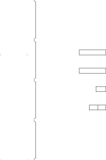
Figure 4.2 The MIPS instruction formats.
The use of a limited number of instruction formats simplifies instruction decoding. However, three instruction formats and a single addressing mode mean that complicated operations and addressing modes will have to be synthesized by the compiler. If these operations and addressing modes are less frequently used, we may not pay much penalty. This is the motivation behind the RISC processors.
Memory Usage
The MIPS uses a conventional memory layout. A program’s address space consists of three parts: code, data, and stack. The memory layout of these three components is shown in Figure 4.3. The text segment, which stores instructions, is placed at the bottom of the user address space at 0x4000000.
The data segment is placed above the text segment and starts at 0x10000000. The data segment is divided into static and dynamic areas. The dynamic area grows as memory is allocated to dynamic data structures.
The stack segment is placed at the end of the user address space at 0x7FFFFFFF. It grows downward towards the lower memory address. This placement of segments allows sharing of unused memory by both data and stack segments.

Chapter 4 • MIPS Architecture |
53 |
Memory addresses (in hex)
7FFFFFFF
Stack segment
Dynamic area
Data segment
Static area
10000000
Text segment
4000000
Reserved
0
Figure 4.3 MIPS memory layout.
Summary
We have presented the basic details of the MIPS architecture. The MIPS32 architecture provides 32 general-purpose registers, a program counter register, and two specialpurpose registers. Each register is 32 bits long. The two special-purpose registers are used by the multiply and divide instructions. MIPS effectively supports only a single addressing mode.
We have not discussed the MIPS instruction set and other details here. We devote the next part of the book to this purpose. In the remainder of this part, we look at a few other RISC architectures.
Web Resources
MIPS32 documentation is available from the MIPS Web site. The MIPS32 Architecture for Programmers, which consists of three volumes, describes the 32-bit MIPS architecture in detail [16, 17, 18]. If you are interested in the 64-bit architecture, it is also de-
54 |
Guide to RISC Processors |
scribed in a three-volume manual MIPS64 Architecture for Programmers [19, 20, 21]. These manuals are available from www.mips.com/content/Documentation/ MIPSDocumentation.

5
SPARC Architecture
This chapter gives details about the SPARC architecture. After a brief introduction, we describe the SPARC architecture in depth. We start our discussion with a description of its register set. Following this we describe its addressing modes. It supports the two addressing modes we described in Chapter 2. The SPARC instruction set details are presented next. The following section describes how procedures are invoked in the SPARC architecture. This section also provides information on SPARC’s parameter-passing mechanism and window management. We conclude the chapter with a summary.
Introduction
The SPARC architecture was initially developed by Sun and is based on the RISC II design from the University of California, Berkeley. SPARC stands for Scalable Processor ARChitecture. Unlike other companies, Sun was wise to make this an open standard and not to manufacture the processor itself. Sun licensed different chip manufacturers to fabricate the processor. Because SPARC is a specification at the ISA level, manufacturers can choose to design their version to suit the target price range and to improve efficiency. For example, implementation of the cache is completely transparent at the ISA level.
The initial SPARC specification SPARC Version 7, introduced in 1987, was a 32-bit processor. SUN and Fujitsu implemented the first SPARC processor. In the following year, SUN introduced the first VME bus-based Sun 4 SPARC workstation. In 1989, SPARC International was set up by SUN and others as the industry body to maintain SPARC as an open architecture, to facilitate distribution of SPARC information and licensing of technology.
The SPARC Version 8 was published in 1990. This is still a 32-bit architecture. The 64-bit SPARC version (Version 9) was introduced in 1993. In 1995, Fujitsu through their SPARC64 and SUN with their UltraSPARC processor introduced 64-bit workstations. A more detailed history of SPARC and its implementations is available from several sources, including [26, 13, 27].
55

56 |
Guide to RISC Processors |
In this chapter, we present details about the 64-bit version. Like the MIPS, it also uses the load/store architecture we discussed in Chapter 2. We start our discussion with the register set. The following sections cover the addressing mode and instruction set details.
Registers
The SPARC register set organization is different from the MIPS architecture discussed in the last chapter. At any time, a user’s program sees 32 general-purpose 64-bit registers r0 through r31. These 32 registers are divided into four groups of eight registers each, as shown in Figure 5.1. As in the MIPS architecture, register zero r0 is hardwired to constant zero.
General-purpose registers r0 to r7 are used as the global registers. It also maintains another set of eight alternate global registers (see Figure 5.2). The AG (Alternate Global) field of the Processor State (PSTATE) register determines which global register set is used. By keeping global variables in the global registers, we can completely avoid accessing memory for procedure calls and returns. A similar mechanism is also used by the Itanium.
The SPARC architecture uses the register windows shown in Figure 5.2. A register window has 24 registers consisting of in, local, and out registers. The out registers of one set overlap the in registers of the adjacent set. This reduces the overhead in parameter passing. The Current Window Pointer (CWP) register gives the current window information. The value of CWP can be incremented or decremented by two instructions: the restore instruction decrements the CWP register, and the save instruction increments it. We give details of these two instructions later.
An implementation may have from 64 to 528 registers. Thus, in an implementation with the minimum number of 64 registers, we can have three register sets (8 global, 8 alternate global, three sets of 16 registers each). When the maximum number of registers is implemented, we can have 32 register sets. An implementation can define NWINDOWS to specify the number of windows, which ranges from 3 to 32. These window sets are organized as a circular buffer. Thus, the CWP arithmetic is done modulo NWINDOWS.
Condition Code Register This register provides two 4-bit integer condition code fields: xcc and icc. Each field consists of four bits, as shown below:
7 |
6 |
5 |
4 |
3 |
2 |
1 |
0 |
|
n |
z |
v |
c |
|
n |
z |
v |
c |
|
xcc |
|
|
|
icc |
|
||
The n bit sign flag records whether the result of the last instruction that affects the condition codes is negative (n = 1) or positive (n = 0). The xcc condition codes record status information about the result of an operation when the operands are 64 bits (the “x” stands for extended). The icc records similar information for 32-bit operands. For example, if the result is 00000000F000FFFFH, the n bit of icc is set because the 32-bit result is a negative number. However, the 64-bit result is positive; therefore, the n bit is cleared.
Chapter 5 • SPARC Architecture |
57 |
|
|
63 |
0 |
|
|
r31 |
|
|
i7 |
|
|
|
|
i6 |
|
||
r30 |
|
|
|
||
|
|
i5 |
|
||
r29 |
|
|
|
||
|
|
i4 |
in |
||
r28 |
|
|
|||
|
|
i3 |
registers |
||
r27 |
|
|
|||
|
|
i2 |
|
||
r26 |
|
|
|
||
|
|
i1 |
|
||
r25 |
|
|
|
||
|
|
i0 |
|
||
r24 |
|
|
|
||
|
|
l7 |
|
||
r23 |
|
|
|
||
r22 |
|
|
l6 |
|
|
r21 |
|
|
|
l5 |
|
r20 |
|
|
|
l4 |
local |
r19 |
|
|
l3 |
registers |
|
r18 |
|
|
l2 |
|
|
r17 |
|
|
l1 |
|
|
r16 |
|
|
l0 |
|
|
r15 |
|
|
o7 |
|
|
|
|
o6 |
|
||
r14 |
|
|
|
||
|
|
o5 |
|
||
r13 |
|
|
|
||
|
|
o4 |
out |
||
r12 |
|
|
|||
|
|
o3 |
registers |
||
r11 |
|
|
|||
|
|
o2 |
|
||
r10 |
|
|
|
||
|
|
o1 |
|
||
r9 |
|
|
|
||
|
|
o0 |
|
||
r8 |
|
|
|
||
|
|
g7 |
|
||
r7 |
|
|
|
||
r6 |
|
|
g6 |
|
|
r5 |
|
|
g5 |
|
|
r4 |
|
|
g4 |
global |
|
r3 |
|
|
g3 |
registers |
|
r2 |
|
|
g2 |
|
|
r1 |
|
|
g1 |
|
|
r0 |
|
Hardwired to 0 |
g0 |
|
|
63 0
PC
63 0
nPC
4 0
CWP
7 4 3 0
xcc icc
CCR
Figure 5.1 Register set in the SPARC V9 architecture (CWP: Current Window Pointer; CCR: Condition Code Register).
The zero bit indicates if the result is zero: z = 1 if the result is zero; otherwise, z = 0. The overflow bit v indicates whether the result, when treated as a signed number, is within the range of 64 bits (xcc) or 32 bits (icc). This bit is useful to detect overflow in signed arithmetic operations. The carry bit c keeps information on whether there was a carry-out from bit 63 (xcc) or bit 31 (icc). It is useful to detect overflow in unsigned arithmetic operations.

58 |
|
|
|
|
|
|
|
|
|
|
|
Guide to RISC Processors |
||
|
Window (CWP |
|
|
1) |
|
|
|
|
|
|
|
|
||
|
|
|
|
|
|
|
|
|
|
|||||
|
|
|
|
|
|
|
|
|
|
|
|
|
|
|
|
r31 |
|
|
|
o7 |
|
|
|
|
|
|
|
|
|
|
. |
out |
. |
|
|
|
|
|
|
|
|
|||
|
. |
|
|
. |
|
|
|
|
|
|
|
|
||
|
. |
registers . |
|
|
|
|
|
|
|
|
||||
|
r24 |
|
|
|
o0 |
|
|
|
|
|
|
|
|
|
|
|
|
|
|
|
|
|
|
|
|
|
|
|
|
|
r23 |
|
|
|
l7 |
|
|
|
|
|
|
|
|
|
|
. |
local . |
|
|
|
|
|
|
|
|
||||
|
. |
|
|
. |
|
|
|
|
|
|
|
|
||
|
. |
registers . |
|
|
|
|
|
|
|
|
||||
|
r16 |
|
|
|
l0 |
Window (CWP) |
|
|
|
|
|
|||
|
|
|
|
|
|
|
|
|
|
|
|
|
|
|
|
r15 |
|
|
|
i7 |
r31 |
|
o7 |
|
|
|
|
|
|
|
. |
|
in |
. |
. |
out |
. |
|
|
|
|
|
||
|
. |
|
|
. |
. |
|
. |
|
|
|
|
|
||
|
. |
registers . |
. |
registers . |
|
|
|
|
|
|||||
|
r8 |
|
|
|
i0 |
r24 |
|
o0 |
|
|
|
|
|
|
|
|
|
|
|
|
|
|
|
|
|
|
|
|
|
63 |
|
|
0 |
r23 |
|
l7 |
|
|
|
|
|
|||
|
|
|
|
|
|
|
. |
local . |
|
|
|
|
|
|
|
|
|
|
|
|
|
. |
|
. |
|
|
|
|
|
|
|
|
|
|
|
|
. |
registers . |
|
|
|
|
|
|
|
|
|
|
|
|
|
r16 |
|
l0 |
|
Window (CWP + 1) |
|||
|
|
|
|
|
|
|
|
|
|
|
|
|
|
|
|
|
|
|
|
|
|
r15 |
|
i7 |
|
r31 |
|
o7 |
|
|
|
|
|
|
|
|
. |
in |
. |
. |
out |
. |
|
|
|
|
|
|
|
|
|
. |
|
. |
. |
|
. |
|
|
|
|
|
|
|
|
|
. |
registers . |
. |
registers . |
|
|||
|
|
|
|
|
|
|
r8 |
|
i0 |
|
r24 |
|
o0 |
|
|
|
|
|
|
|
|
|
|
|
|
|
|
|
|
|
|
|
|
|
|
|
63 |
|
0 |
|
r23 |
|
l7 |
|
|
|
|
|
|
|
|
|
|
|
. |
local . |
|
||
|
|
|
|
|
|
|
|
|
|
. |
|
. |
|
|
|
|
|
|
|
|
|
|
|
|
. |
registers . |
|
||
|
|
|
|
|
|
|
|
|
|
|
r16 |
|
l0 |
|
|
|
|
|
|
|
|
|
|
|
|
|
|
|
|
|
|
|
|
|
|
|
|
|
|
|
r15 |
|
i7 |
|
|
|
|
|
|
|
|
|
|
|
. |
in |
. |
|
|
|
|
|
|
|
|
|
|
|
|
. |
|
. |
|
|
|
|
|
|
|
|
|
|
|
|
. |
registers . |
|
||
|
|
|
|
|
|
|
|
|
|
|
r8 |
|
i0 |
|
|
|
|
|
|
|
|
|
|
|
|
|
|
|
|
|
|
|
|
|
|
|
|
|
|
63 |
|
0 |
|
|
|
|
|
|
|
|
|
|
|
|
|
|
|
|
|
|
|
r7 |
alternate |
g7 |
|
r7 |
|
|
g7 |
|
|
|||
|
|
. |
|
|
|
|
. |
|
. |
|
|
. |
|
|
|
|
. |
global . |
|
. |
|
global . |
|
|
|||||
|
|
. |
registers |
. |
|
. |
|
registers . |
|
|
||||
|
|
r1 |
g1 |
|
r1 |
|
|
g1 |
|
|
||||
|
|
|
|
|
|
|
|
|
|
|
||||
|
|
r0 |
|
0 |
|
g0 |
|
r0 |
0 |
g0 |
|
|
||
|
|
63 |
|
|
|
|
0 |
|
63 |
|
|
0 |
|
|
Figure 5.2 Register windows in the SPARC architecture.
Addressing Modes
The SPARC architecture supports the two addressing modes we discussed in Chapter 2: the register indirect with index and register indirect with immediate addressing modes.
•Register Indirect with Immediate: This addressing mode is similar to the MIPS addressing mode discussed in the last chapter. It computes the effective address as

Chapter 5 • SPARC Architecture |
59 |
Effective address = contents of Rx + imm13.
The base register Rx can be any general-purpose register. A 13-bit signed constant imm13 can be specified as the displacement. This constant is sign-extended to 64 bits and added to the Rx register (see our discussion on sign extension in Appendix A).
•Register Indirect with Index: This addressing mode computes the effective address as the sum of two register contents.
Effective address = contents of Rx + contents of Ry.
The base register Rx and the index register Ry can be any general-purpose registers.
There is no register indirect addressing mode in which the contents of a register are taken as the effective address. But we can emulate this addressing mode by making the constant zero in the first addressing mode, or using r0 as the index register in the second addressing mode. Note that r0 is hardwired to read zero.
Instruction Format
All SPARC instructions are 32 bits long. The instruction format uses two opcode fields: the most significant two bits op (bits 30 and 31) identify a major operation group and the second field, op2 or op3, specifies the actual instruction. A sample of the instruction formats is shown in Figure 5.3. The first two formats show how most instructions that use three addresses are encoded. If an immediate value is used, the second format is used. The i bit specifies whether one of the source operands is in a register (i = 0) or a constant (i = 1).
The next three formats are used for sethi and conditional branch instructions. The sethi instruction moves a 22-bit constant into a register (see page 62). The SPARC architecture supports two types of conditional branch instructions. These branch instructions are also discussed later.
The final format is used for procedure calls. We can specify a 30-bit signed displacement value as part of this instruction.
Instruction Set
This section gives details about the SPARC instruction set. Procedure invocation and parameter-passing details are discussed in the next section.
Data Transfer Instructions
Because the SPARC follows the load/store architecture, only load and store instructions can move data between a register and memory. The load instruction
60 |
|
|
|
|
|
|
|
|
|
|
|
|
|
|
|
|
Guide to RISC Processors |
||||
|
General Format |
|
|
|
|
|
|
|
|
|
|
|
|
|
|
|
|||||
31 |
30 |
29 |
|
25 24 |
|
|
|
19 |
18 |
|
14 13 |
12 |
5 |
4 |
0 |
|
|||||
|
|
|
|
|
|
|
|
|
|
|
|
|
|
|
|
|
|
|
|
||
|
op |
|
rd |
|
|
|
op3 |
|
|
rs1 |
|
i |
|
|
|
|
rs2 |
|
|||
|
|
|
|
|
|
|
|
|
|
|
|
|
|||||||||
|
|
|
|
|
|
|
|
|
|
|
|
|
|
|
|
|
|
|
|||
|
|
|
|
|
|
|
|
|
|
Register−register instructions (i = 0) |
|
|
|
||||||||
31 |
30 |
29 |
|
25 24 |
|
|
|
19 |
18 |
|
14 13 |
12 |
|
|
|
0 |
|
||||
|
|
|
|
|
|
|
|
|
|
|
|
|
|
|
|
|
|
|
|
|
|
|
op |
|
rd |
|
|
|
op3 |
|
|
rs1 |
|
i |
|
|
imm13 |
|
|
|
|||
|
|
|
|
|
|
|
|
|
|
|
|
|
|
|
|
|
|
|
|||
|
|
|
|
|
|
|
|
|
Register−immediate instructions (i = 1) |
|
|
|
|||||||||
|
SETHI and Branch Format |
|
|
|
|
|
|
|
|
|
|
||||||||||
31 |
30 |
29 |
|
25 24 |
22 |
21 |
|
|
|
|
|
|
|
|
|
1 |
|
||||
|
|
|
|
|
|
|
|
|
|
|
|
|
|
|
|
|
|
|
|
||
|
op |
|
rd |
|
|
op2 |
|
|
|
|
|
imm22 |
|
|
|
|
|
||||
|
|
|
|
|
|
|
|
|
|
|
|
|
|
|
|
|
|
|
|
|
|
|
|
|
|
|
|
|
|
|
|
|
|
|
SETHI instruction |
|
|
|
|
|
|||
31 |
30 29 30 |
25 24 |
22 |
21 |
|
|
|
|
|
|
|
|
|
1 |
|
||||||
|
|
|
|
|
|
|
|
|
|
|
|
|
|
|
|
|
|
|
|||
|
op |
a |
cond |
|
op2 |
|
|
|
|
|
disp22 |
|
|
|
|
|
|||||
|
|
|
|
|
|
|
|
|
|
|
|
|
|
|
|
|
|
|
|
|
|
|
|
|
|
|
|
|
|
|
|
|
|
|
Branch instructions |
|
|
|
|
|
|||
31 |
30 29 30 |
25 24 |
22 21 20 19 18 |
|
|
|
|
|
|
|
1 |
|
|||||||||
|
|
|
|
|
|
|
|
|
|
|
|
|
|
|
|
|
|
|
|
|
|
|
op |
a |
cond |
|
op2 |
cc1 |
cc0 |
p |
|
|
disp19 |
|
|
|
|
|
|||||
|
|
|
|
|
|
|
|
|
|
|
|||||||||||
|
|
|
|
|
|
|
|
|
|
|
|
|
|
|
|
|
|
|
|||
|
|
|
|
|
|
|
|
|
|
Branch with prediction instructions |
|
|
|
||||||||
|
CALL Format |
|
|
|
|
|
|
|
|
|
|
|
|
|
|
|
|||||
31 |
30 |
29 |
|
|
|
|
|
|
|
|
|
|
|
|
|
|
|
|
1 |
|
|
|
|
|
|
|
|
|
|
|
|
|
|
|
|
|
|
|
|
|
|
|
|
|
op |
|
|
|
|
|
|
|
|
|
|
|
disp30 |
|
|
|
|
|
|||
|
|
|
|
|
|
|
|
|
|
|
|
|
|
|
|
|
|
|
|
|
|
Call instructions
Figure 5.3 Some sample SPARC instruction formats.
ldsb [address],Rd
loads the signed byte in memory at address into the Rd register. Because it is a signed byte, it is sign-extended to 64 bits and loaded into Rd. To load signed halfword and word, use ldsh and ldsw, respectively. The corresponding unsigned load instructions are ldub, lduh, and lduw. These instructions zero-extend the data to 64 bits before loading into the Rd register. To load a 64-bit extended word, use ldx.
Chapter 5 • SPARC Architecture |
61 |
|||
|
Table 5.1 The conditional data movement instructions |
|||
|
Mnemonic |
Operation |
Test condition |
|
|
|
|
|
|
|
movrz |
Move if register zero |
Rs1 = 0 |
|
|
movrnz |
Move if register not zero |
Rs1 =0 |
|
|
movrlz |
Move if register less than zero |
Rs1 < 0 |
|
|
movrlez |
Move if register less than or equal to zero |
Rs1 ≤ 0 |
|
|
movrgz |
Move if register greater than zero |
Rs1 > 0 |
|
|
movrgez |
Move if register greater than or equal to zero |
Rs1 ≥ 0 |
|
Unlike the load instructions, store instructions do not need to be signor zero-extended. Thus, we do not need separate signed and unsigned versions. The store instruction
stb Rs,[address]
stores the lower byte of rs in memory at address. To store a halfword, word, and extended word, use sth, stw, and stx, respectively.
In addition to these load and store instructions, the SPARC provides two groups of conditional data movement instructions. One group moves data if the register contents satisfy a certain condition; the other group checks the condition codes. We briefly describe these two groups of instructions next.
There are five instructions in the first group. We describe one instruction as the others follow the same behavior except for the condition tested. The instruction
movrz Rs1,Rs2,Rd or movrz Rs1,imm10,Rd
copies the second operand (either Rs2 or imm10) into Rd if the contents of Rs1 are zero. The other instructions in this group test conditions such as “less than zero,” and “greater than or equal to zero” as shown in Table 5.1.
The second group of move instructions tests the condition codes. The format is
movXX |
i_or_x_cc,Rs1,Rd or |
movXX |
i_or_x_cc,imm11,Rd |
It copies the contents of the second operand (Rs1 or imm11) into Rd if the condition XX is satisfied. The instruction can specify whether to look at xcc or icc condition codes. The conditions tested are the same ones used in the conditional branch instruction that we discuss later. For this reason, we just give one example instruction to explain the format and semantics. The move (move if equal) instruction
move i_or_x_cc,Rs1,Rd
moves contents of Rs1 to Rd if z = instructions, see the conditional branch
1. For a full list of conditions tested by these instructions in Table 5.3.