

Стеклянные передвижные перегородки
.pdf
|
|
|
|
ТЕХНИЧЕСКАЯ ИНФОТЕКА |
|
|
|
|
|
|
|
HSW Support |
|
|
Track Rails |
www.know-house.ru/infotek/ |
|
|
|
|
|
||
and Guide Elements |
|
|
|
|
|
|
|
|
|
|
|
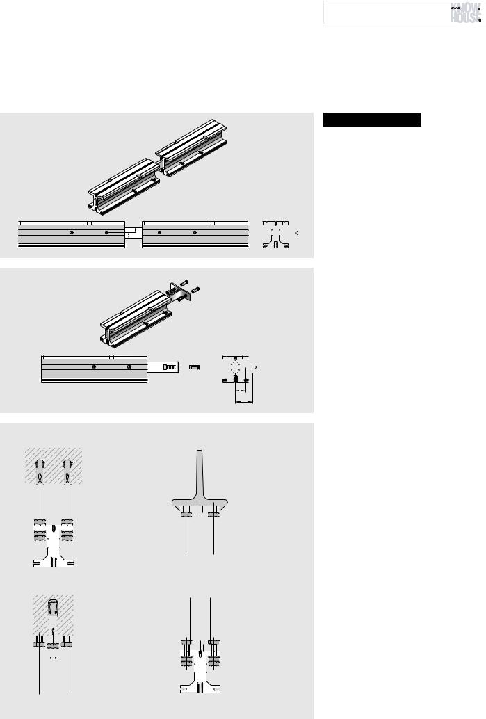
Track rails and modules
Straight track rail
|
150 |
150 |
300 |
|
50 |
|
50 |
|
9 |
|
36 |
75 |
ø |
|
|
Stacking track rail |
Track rail at closed wall position |
72
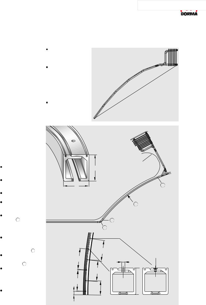
Flexible and stable
Horizontal sliding walls can be constructed in a wide range of different configurations to suit the site of installation, prevailing structural conditions and the planning concept.
With DORMA HSW systems, a variety of designs can be implemented with ease. Straight, segmented and curved track rails can be combined to produce virtually any serpentine shape required. The track rails in the form of hollow sections combine all the virtues of light weight, stability and torsional stiffness. And when combined with the HSW substructure, installation becomes even easier. Flexibility and stability mean that even unusual system configurations can be implemented without problem to give maximum functional reliability.
Straight track rail
For a straight-line system configuration, a drill hole interval of 300 mm in the track rail is sufficient, while the stacking area requires an interval of 150 mm. Where the track assumes an angle of 161-179°, the track rail is mitred, while at angles between 90 and 160°, a cast curve is incorporated. The standard modules available are indicated in the adjacent illustrations.
90° T-piece |
40 |
|
|
|
|
|
|
200 |
|
|
|
36 |
|
|
ø 9 |
40 |
60 |
60 |
40 |
|
400 |
|
|
135° T-piece
80 |
36 |
|
Left |
36 |
|
ø 9 |
|
|
|
|
or right |
30 |
|
30 |
|
|
400 |
|
90° L-piece |
40 |
|
|
|
|
|
|
|
200 |
|
90° |
|
|
|
|
|
60 |
|
ø 9 |
|
|
|
|
|
36 |
60 |
40 |
|
|
|
200 |
curved section cornered |
curved section cornered |
|
90° angle left/right |
outside 85°/90° |
outside 45° |
|
|
|
|
|
22.5° |
136 |
36 |
|
36 |
|
|
136 |
85°/90° |
136 |
|
90° |
|
45° |
|||
|
|
136 |
||
|
|
|
|
14 |
07/08 |
ТЕХНИЧЕСКАЯ ИНФОТЕКА 

 www.know-house.ru/infotek/


Segmented track rail
With the segmented track rail, it is possible to implement the DORMA HSW as a polygonal partition or frontage. In so doing, it is essential to note the following requirements:
Curved track rail
A curved track rail is also available where a curved DORMA HSW system configuration is required. The most important technical prerequisites for this are as follows:
only non-pivoting sliding panels may be installed in the curved track rail section; the track rail must be straight in the parking or stacking area;
no top locking element can be installed;
each panel is provided with two face-mounted floor bolts;
a 100 mm straight track section 1 is necessary as the transition from the curved track rail to the straight stacking track rail; blends from the curved configuration to a straight line can be implemented using standard modules 2 ;
the smallest curve radius is 3500 mm (smaller radii on application) 3 ;
the feasibility of elliptic system configurations must be considered on a case-by- case basis – for this, drawings will be necessary; the start and end points of the curve are always provided with a 90° saw cut (radial saw cut).
the panel width and segment chord length must be properly coordinated; segment panels are
provided at the bottom with locks or face-mount- ed floor bolts and the end face profile covers are equipped with additional buffers for collision protection;
it is important to ensure that the opening sweep of single action and double action panels does not give rise to collisions.
Collision curve
75
72
Curved track rail, bolted double shell construction
3 Rmin
of the neutral fibre = 3500 mm
1
2
300 |
Countersunk screw |
|
DIN 7991 |
||
|
||
|
M6x10. A2 |
300 |
ø 9 |
|
300 |
300 |
|
50 |
200 |
|
07/08 |
15 |
|
|
|
|
ТЕХНИЧЕСКАЯ ИНФОТЕКА |
|
|
|
|
|
|
|
HSW Bearing and |
|
|
Substructure |
www.know-house.ru/infotek/ |
|
|
|
|
|
||
Locating Elements |
|
|
|
|
|
|
|
|
|
|
|
The System
Problems and solutions
Installing a horizontal sliding wall system invariably requires a certain set of structural conditions to be established. The system will need to be precisely aligned vertically - usually subsequent to installation - as well as being exactly configured and securely located. Because DORMA HSW systems do not use floor-level supports and floor tracks, the system requirements and all their technical properties must be taken into account when designing the substructure and its incorporation within the ceiling. This often very costly planning process is normally undertaken by the fabricator as the installation company, and alongside the calculations there are many individual structural and installation procedures involved. The new DORMA substructure system is of modular construction and is designed to significantly reduce on-site installation cost and time. This concept also offers the particular flexibility required to overcome structural constraints, such as the presence of air conditioning shafts or pre-existing electrical systems in the ceiling.
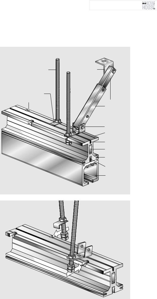
System design
The DORMA substructure consists primarily of the following components: substructure profile with modules for branching to the stacking area, threaded rods for suspension of the profile(s), and standard square section tubes with appropriate fixings and ceiling brackets for bracing and stiffening the construction.
M10 threaded rod |
Pivoting angle bracket |
Fixing plate |
|
Milled “U” recess |
Standard square |
|
|
|
section tubes |
|
Pivot fixing |
|
Substructure |
|
profile |
|
Upper |
|
bolting channel |
|
Centre channel |
|
Lateral |
|
bolting channel |
|
Lower |
|
bolting channel |
|
Track rail |
16 |
07/08 |
ТЕХНИЧЕСКАЯ ИНФОТЕКА 

 www.know-house.ru/infotek/


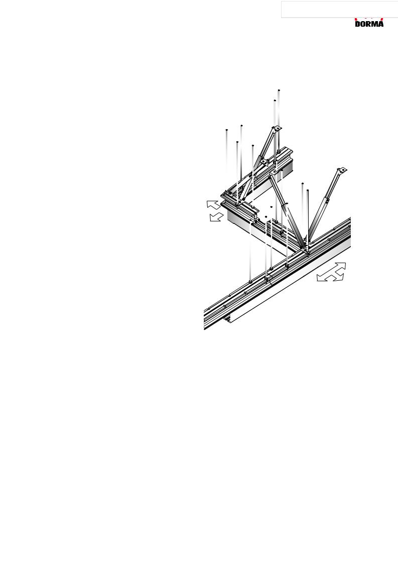
Safety and flexibility
The DORMA substructure has been developed on the basis of extensive practical experience of the requirements involved in this kind of system. Consequently, the profile incorporates features that greatly facilitate installation and ensure that pre-existing structural factors can be accommodated with maximum flexibility.
Various bolting channels run the whole length of the profile, allowing bolts to be inserted easily at any location within the system configuration. So there is no need for pre-drilling and thread cutting in order to mount the track rails onto the substructure.
Bolted connections can be made directly through the lower bolting channel. The problem of removing drillings and filings from the track rails is thus also a thing of the past.
Bolting channels on both sides of the profile can be used e.g. for fixing the brackets needed for attaching the ceiling retention elements. In addition, centering grooves on all main profile surfaces facilitate overhead drilling, e.g. for accessory attachment. Welding brackets designed for bolting onto the profile provide another option, allowing the DORMA system to be utilised for additional customer-specific applications.
The substructure profile is suspended from threaded rods. These are first placed in the U-recesses using fixing plates that lock into the upper bolting channel. Each pair of threaded rods is regarded as constituting one suspension point. Here again the system remains exceptionally flexible: the staggered U-recesses positioned at intervals of 100 mm enhance the ability of the system to accommodate structural constraints. Depending on the weight of the system and the permitted deflection, it is possible to span a distance of up to 2.10 m between two suspension points.
Standard flat steel bars can be inserted in the centre channel to further stiffen the profile, particularly in the area of the joints. This means that just one suspension point in the vicinity of the joint can be provided instead of the two - one either side of the joint - that are usually needed. So existing building installations of all types can be effectively bypassed. Once the substructure has been installed, the HSW system is vertically aligned and fixed directly via the threaded rods. Subsequent adjustments, e.g. after the building has settled into its foundations, can also be carried out by the same means.
|
|
|
|
|
|
|
|
|
|
|
|
|
|
|
|
|
|
|
|
|
|
|
|
|
|
|
|
|
|
|
|
|
|
|
|
|
|
|
|
|
|
|
|
|
|
|
|
|
|
|
|
|
|
|
|
|
|
|
|
|
|
|
|
|
|
|
|
|
|
|
|
|
|
|
|
|
|
|
|
|
|
|
|
|
|
|
|
|
|
|
|
|
|
|
|
|
|
|
|
|
|
|
|
|
|
|
|
|
|
|
|
|
|
|
|
|
|
|
|
|
|
|
|
|
|
|
|
|
|
|
|
|
|
|
|
|
|
|
|
|
|
|
|
|
|
|
|
|
|
|
|
|
|
|
|
|
|
|
|
|
|
|
|
|
|
|
|
|
|
|
|
|
|
|
|
|
|
|
|
|
|
|
|
|
|
|
|
|
|
|
|
|
|
|
|
|
|
|
|
|
|
|
|
|
|
|
|
|
|
|
|
|
|
|
|
|
|
|
|
|
|
|
|
|
|
|
|
|
|
|
|
|
|
|
|
|
|
|
|
|
|
|
|
|
|
|
|
|
|
|
|
|
|
|
|
|
|
|
|
|
|
|
|
|
|
|
|
|
|
|
|
|
|
|
|
|
|
|
|
|
|
|
|
|
|
|
|
|
|
|
|
|
|
|
|
|
|
|
|
|
|
|
|
|
|
|
|
|
|
|
|
|
|
|
|
|
|
|
|
|
|
|
|
|
|
|
|
|
|
|
|
|
|
|
|
|
|
|
|
|
|
|
|
|
|
|
|
|
|
|
|
|
|
|
|
|
|
|
|
|
|
|
|
|
|
|
|
|
|
|
|
|
|
|
|
|
|
|
|
|
|
|
|
|
|
|
|
|
|
|
|
|
|
|
|
|
|
|
|
|
|
|
|
|
|
|
|
|
|
|
|
|
|
|
|
|
|
|
|
|
|
|
|
|
|
|
|
|
|
|
|
|
|
|
|
|
|
|
|
|
|
|
|
|
|
|
|
|
|
|
|
|
|
|
|
|
|
|
|
|
|
|
|
|
|
|
|
|
|
|
|
|
|
|
|
|
|
|
|
|
|
|
|
|
|
|
|
|
|
|
|
|
|
|
|
|
|
|
|
|
|
|
|
|
|
|
|
|
|
|
|
|
|
|
|
|
|
|
|
|
|
|
|
|
|
|
|
|
|
|
|
|
|
|
|
|
|
|
|
|
|
|
|
|
|
|
|
|
|
|
|
|
|
|
|
|
|
|
|
|
|
|
|
|
|
|
|
The forces (shown |
|
||||||
|
|
|
|
|
|
|
|
|
|||||||
|
|
|
|
|
|
|
by arrows) that occur |
|
|||||||
|
|
|
|
|
|
during opening and |
|
||||||||
|
|
|
|
|
|
closing of the sliding wall |
|
||||||||
|
|
|
|
|
|
|
|||||||||
|
|
|
|
|
|
system must be absorbed |
|
||||||||
|
|
|
|
|
|
by appropriately located |
|
||||||||
|
|
|
|
|
|
bracing elements. |
|
||||||||
|
|
|
|||||||||||||
The standard square section |
The modular design of the |
||||||||||||||
tubes offer extra safety, |
DORMA substructure is |
||||||||||||||
especially where the sliding |
precisely matched to the |
||||||||||||||
panels deviate from a straight |
modules of the DORMA HSW |
||||||||||||||
line. Panel sway must be |
track rail. The structural |
||||||||||||||
effectively countered by the |
elements can be mixed and |
||||||||||||||
structural design adopted at |
matched as desired with the |
||||||||||||||
such locations. Diagonal |
result that a small number of |
||||||||||||||
struts that counteract the |
component types is sufficient |
||||||||||||||
pressure load stabilise the |
to create a complex, flexible |
||||||||||||||
system in the area of the |
system that conforms fully to |
||||||||||||||
stacked panels. The |
all safety requirements. |
||||||||||||||
telescopic square section |
A drawing of the required |
||||||||||||||
tubes are connected as |
substructure can be |
||||||||||||||
additional bracing elements |
requested from DORMA to |
||||||||||||||
(struts) to the substructure by |
supplement the HSW system |
||||||||||||||
a pivot fixing. The struts are |
drawing always supplied with |
||||||||||||||
bolted to the ceiling using |
the quotation. |
||||||||||||||
the appropriate angle |
|
|
|
|
|
|
|
|
|
|
|||||
brackets. |
|
|
|
|
|
|
|
|
|
|
|||||
07/08 |
17 |

HSW Bearing and |
|
|
Substructure |
|
|
||
Locating Elements |
|
|
|
|
|
|
|
Planning details
Max. 2 mm deflection between two suspension points
In order to prevent system sway, every second suspension point must be reinforced by a strut. The substructure profile ends (travel path and stacking area) should ideally be directly connected to the masonry or to existing structural members.
Table for the calculation of the max. distance dimension
|
|
|
|
|
|
|
|
|
|
|
|
|
|
|
|
|
|
|
|
|
|
|
|
|
|
|
|
|
|
|
|
|
|
|
|
|
|
|
|
|
|
|
|
|
|
|
|
|
|
|
|
|
|
|
|
|
|
|
|
|
|
|
|
|
|
|
|
|
|
|
|
|
|
|
|
|
|
|
|
|
|
|
|
|
|
|
|
|
|
|
|
|
|
|
|
|
|
|
|
|
|
|
|
|
|
|
|
|
|
|
|
|
|
|
|
|
|
|
|
|
|
|
|
|
|
|
|
|
|
|
|
|
|
|
|
|
|
|
|
|
|
|
|
|
|
|
|
|
|
|
|
|
|
|
|
|
|
|
|
|
|
|
|
|
|
|
|
|
|
|
|
|
|
|
|
|
|
|
|
|
|
|
|
|
|
|
|
|
|
|
|
|
|
|
|
|
|
|
|
|
|
|
|
|
|
|
Front |
|
|
|
|
|
AM |
|
|
|
|
Parking area |
|||||||||||||
|
|
|
|
|
|
|
|
|
|
|
|
|
|
|
|
|
|
|
|
|
|
|
|
|
|
|
|
|
|
|
|
|
|
|
|
|
|
|
F |
|
|
|
|
|
|
|
|
|
|
|
|
|
|
|
|
|
|
|
|
|
|
|
|
|
|
|
|
|
|
|
|
|
|
|
|
|
|
|
|
|||||||
|
|
|
|
|
|
|
|
|
|
|
|
|
|
|
|
|||||||||||||
|
|
|
|
|
AM max. |
|
|
|
|
|
|
|
|
|
||||||||||||||
|
|
|
|
|
|
F = Force |
||||||||||||||||||||||
|
|
|
|
|
|
|
|
|
|
|||||||||||||||||||
|
|
|
|
F |
|
|
AM |
|
|
|
|
|
|
|
|
|||||||||||||
|
|
|
|
|
|
|
|
|
|
|
|
|
|
|
|
|
|
|
|
|
|
AM = Distance dimension |
||||||
|
|
60 kg/m |
|
2050 mm |
|
|
|
|
|
|
|
|
||||||||||||||||
|
|
|
|
|
|
|
|
|
|
|
|
|||||||||||||||||
|
|
|
|
|
|
|
|
|
|
|
|
|
|
|||||||||||||||
|
|
75 kg/m |
|
1900 mm |
|
|
|
|
|
|
|
|
|
|
|
|
|
|
|
|||||||||
|
|
|
|
|
|
|
|
|
|
|
|
|
|
|||||||||||||||
|
|
90 kg/m |
|
1750 mm |
|
|
|
|
|
|
|
|
|
|
|
|
|
|
|
|||||||||
|
|
|
|
|
|
|
|
|
|
|
|
|
|
|||||||||||||||
|
|
105 kg/m |
|
1750 mm |
|
|
|
|
|
|
|
|
|
|
|
|
|
|
|
|||||||||
|
|
|
|
|
|
|
|
|
|
|
|
|
|
|||||||||||||||
|
|
120 kg/m |
|
1600 mm |
|
|
|
|
|
|
|
|
|
|
|
|
|
|
|
|||||||||
|
|
|
|
|
|
|
|
|
|
|
|
|
|
|
|
|
|
|
|
|
|
Force example: |
||||||
|
|
135 kg/m |
|
1600 mm |
|
|
|
|
|
|
|
|
||||||||||||||||
|
|
|
|
|
The distance dimension of |
|||||||||||||||||||||||
|
|
|
|
|
|
|
|
|
|
|
|
|
|
|
|
|
|
|
|
|
|
|||||||
|
|
150 kg/m |
|
1450 mm |
|
|
108.98 kg/m = 1710 mm |
|||||||||||||||||||||
|
|
|
|
|
|
|
|
|
|
|
|
|
|
|||||||||||||||
|
|
160 kg/m |
|
1450 mm |
|
|
|
|
|
|
|
|
|
|
|
|
|
|
|
|||||||||
|
|
|
|
|
|
|
|
|
|
|
|
|
|
|
|
|
|
|
|
|
|
|
|
|
|
|
|
|
|
|
|
|
|
|
|
|
|
|
|
|
|
|
|
|
|
|
|
|
|
|
|
|
|
|
|
|
|
|
|
|
|
|
|
|
|
|
|
|
|
|
|
|
|
|
|
|
|
|
|
|
|
|
|
|
|
|
|
|
|
|
|
|
|
|
|
|
|
|
|
|
|
|
|
|
|
|
|
|
|
|
|
|
|
|
|
|
|
|
|
|
|
|
|
|
|
|
|
|
|
|
|
|
|
|
|
|
|
|
|
|
|
|
|
|
ТЕХНИЧЕСКАЯ ИНФОТЕКА 

 www.know-house.ru/infotek/


Calculating the suspension intervals
With a maximum load (panel weight) of 150 kg/m and a permitted deflection of the substructure with track rail of 2 mm, the interval between two suspension points must be no greater than 1.45 m. The table below shows other values for different loads.
Illustrative example of load values
HSW-G characteristic values
Formula for calculating the:
Glazing height
=system height – 0.309 m
=panel height – 0.193 m
Glazing weight
Glass 10 mm = 25.00 kg/m2
Glass 12 mm = 30.00 kg/m2
Door rail weight
Aluminium = 12.00 kg/m
Brass = 14.50 kg/m
Stainl. steel = 13.25 kg/m
Example system |
|
HSW-G system in |
|
stainless steel |
|
System height |
3.50 m |
Glazing thickness |
12 mm |
Calculation
Load
=glazing weight x glazing height + door track weight
=30 kg/m2 x (3.50 m –
0.309 m) + 13.25 kg/m
=30 kg/m2 x 3.191 m +
13.25 kg/m
=108.98 kg/m
18 |
07/08 |
Stacking area design
View from below
|
|
|
|
|
|
|
|
|
|
|
|
|
|
|
|
|
|
|
|
|
|
|
|
|
|
|
|
|
|
|
|
|
|
|
|
|
|
|
|
|
|
|
|
|
|
|
|
|
|
|
|
|
|
|
|
|
|
|
|
|
|
|
|
|
|
|
|
|
|
|
|
|
|
|
|
|
|
|
|
|
|
|
|
|
|
|
|
|
|
|
|
|
|
|
|
|
|
|
|
|
|
|
|
|
|
|
|
|
|
|
|
|
|
|
|
|
|
|
|
|
|
|
|
|
|
|
|
|
|
|
|
|
|
|
|
|
|
|
|
|
|
|
|
|
|
|
|
|
|
|
|
|
|
|
|
|
|
|
|
|
|
|
|
|
|
|
|
|
|
|
|
|
|
|
|
|
|
|
|
|
|
|
|
|
|
|
|
|
|
|
|
|
|
|
|
|
|
|
|
|
|
|
|
|
|
|
|
|
|
|
|
|
|
|
|
|
|
|
|
|
|
|
|
|
|
|
|
|
|
|
|
|
|
|
|
|
|
|
|
|
|
|
|
|
|
|
|
|
|
|
|
|
|
|
|
|
|
|
|
|
|
|
|
|
|
|
|
|
|
|
|
|
|
|
|
|
|
|
|
|
|
|
|
|
|
|
|
|
|
|
|
|
|
|
|
|
|
|
|
|
|
|
|
|
|
|
|
|
|
|
|
|
|
|
|
|
|
|
|
|
|
|
|
|
|
|
|
|
|
|
|
|
|
|
|
|
|
|
|
|
|
|
|
|
|
|
|
|
|
|
|
|
|
|
|
|
|
|
|
|
|
|
|
|
|
|
|
|
|
|
|
|
|
|
|
|
|
|
|
|
|
|
|
|
|
|
|
|
|
|
|
|
|
|
|
|
|
|
|
|
|
|
|
|
|
|
|
|
|
|
|
|
|
|
|
|
|
|
|
|
|
|
|
|
|
|
|
|
|
|
|
|
|
|
|
|
|
|
|
|
|
|
|
|
|
|
|
|
|
|
|
|
|
|
|
|
|
|
|
|
|
|
|
|
|
|
|
|
|
|
|
|
|
|
|
|
|
|
|
|
|
|
|
|
|
|
|
|
|
|
|
|
|
|
|
|
|
|
|
|
|
|
|
|
|
|
|
|
|
|
|
|
|
|
|
|
|
|
|
|
|
|
|
|
|
|
|
|
|
|
|
|
|
|
|
|
|
|
|
|
|
|
|
|
|
|
|
|
|
|
|
|
|
|
|
|
|
|
|
|
|
|
|
|
|
|
|
|
|
|
|
|
|
|
|
|
|
|
|
|
|
|
|
|
|
|
|
|
|
|
|
|
|
|
|
|
|
|
|
|
|
|
|
|
|
|
|
|
|
|
|
|
|
|
|
|
|
|
|
|
|
|
|
|
|
|
|
|
|
|
|
|
|
|
|
|
|
|
|
|
|
|
|
|
|
|
|
|
|
|
|
|
|
|
|
|
|
|
|
|
|
|
|
|
|
|
|
|
|
|
|
|
|
|
|
|
|
|
|
|
|
|
|
|
|
|
|
|
|
|
|
|
|
|
|
|
|
|
|
|
|
|
|
|
|
|
|
|
|
|
|
|
|
|
|
|
|
|
|
|
|
|
|
|
|
|
|
|
|
|
|
|
|
|
|
|
|
|
|
|
|
|
|
|
|
|
|
|
|
|
|
|
|
|
|
|
|
|
|
|
|
|
|
|
|
|
|
|
|
|
|
|
|
|
|
|
|
|
|
|
|
|
|
|
|
|
|
|
|
|
|
|
|
|
|
|
|
|
|
|
|
|
|
|
|
|
|
|
|
|
|
|
|
|
|
|
|
|
|
|
|
|
|
|
|
|
|
|
|
|
|
|
|
|
|
|
|
|
|
|
|
|
|
|
|
|
|
|
|
|
|
|
|
|
|
|
|
|
|
|
|
|
|
|
|
|
|
|
|
|
|
|
|
|
|
|
|
|
|
|
|
|
|
|
|
|
|
|
|
|
|
|
|
|
|
|
|
|
|
|
|
|
|
|
|
|
|
|
|
|
|
|
|
|
|
|
|
|
|
|
|
|
|
|
|
|
|
|
|
|
|
|
|
|
|
|
|
|
|
|
|
|
|
|
|
|
|
|
|
|
|
|
|
|
|
|
|
|
|
|
|
|
|
|
|
|
|
|
|
|
|
|
|
|
|
|
|
|
|
|
|
|
|
|
|
|
|
|
|
|
|
|
|
|
|
|
|
|
|
|
|
|
|
|
|
|
|
|
|
|
|
|
|
|
|
|
|
|
|
|
|
|
|
|
|
|
|
|
|
|
|
|
|
|
|
|
|
|
|
|
|
|
|
|
|
|
|
|
|
|
|
|
|
|
|
|
|
|
|
|
|
|
|
|
|
|
|
|
|
|
|
|
|
|
|
|
|
|
|
|
|
|
|
|
|
|
|
|
|
|
|
|
|
|
|
|
|
|
|
|
|
|
|
|
|
|
|
|
|
|
|
|
|
|
|
|
|
|
|
|
|
|
|
|
|
|
|
|
|
|
|
|
|
|
|
|
|
|
|
|
|
|
|
|
|
|
|
|
|
|
|
|
|
|
|
|
|
|
|
|
|
|
|
|
|
|
|
|
|
|
|
|
|
|
|
|
|
|
|
|
|
|
|
|
|
|
|
|
|
|
|
|
|
|
|
|
|
|
|
|
|
|
|
|
|
|
|
|
|
|
|
|
|
|
|
|
|
|
|
|
|
|
|
|
|
|
|
|
|
|
|
|
|
|
|
|
|
|
|
|
|
|
|
|
|
|
|
|
|
|
|
|
|
|
|
|
|
|
|
|
|
|
|
|
|
|
|
|
|
|
|
|
|
|
|
|
|
|
|
|
|
|
|
|
|
|
|
|
|
|
|
|
|
|
|
|
|
|
|
|
|
|
|
|
|
|
|
|
|
|
|
|
|
|
|
|
|
|
|
|
|
|
|
|
|
|
|
|
|
|
|
|
|
|
|
|
|
|
|
|
|
|
|
|
|
|
|
|
|
|
|
|
|
|
|
|
|
|
|
|
|
|
|
|
|
|
|
|
|
|
|
|
|
|
|
|
|
|
|
|
|
|
|
|
|
|
|
|
|
|
|
|
|
|
|
|
|
|
|
|
|
|
|
|
|
|
|
|
|
|
|
|
|
|
|
|
|
|
|
|
|
|
|
|
|
|
|
|
|
|
|
|
|
|
|
|
|
|
|
|
|
|
|
|
|
|
|
|
|
|
|
|
|
|
|
|
|
|
|
|
|
|
|
|
|
|
|
|
|
|
|
|
|
|
|
|
|
|
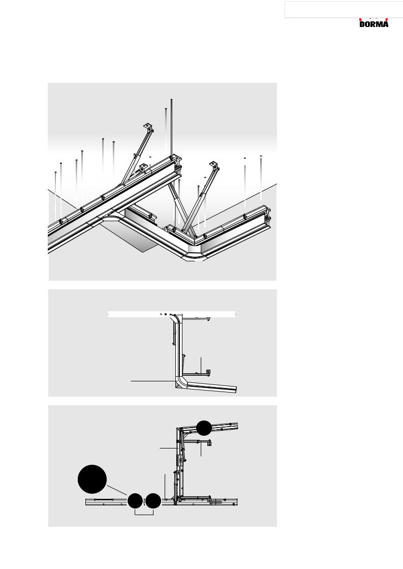
Substructure |
|
Track rail |
|
|
|
Detachable |
|
|
|
90° branch module |
|
|
|
|
|
|
||||||||||||||||||||||||||||||||||||||
|
|
|
|
|
|
|
|
|
|
|
|
|
|
|
|
|
||||||||||||||||||||||||||||||||||||||||||
|
|
|
|
|
|
|
|
|
|
|
|
|
|
|
|
|
|
|
|
|
|
|
|
section |
|
|
|
|
|
|
|
|
|
|
|
|
|
|
|
|
|
|
|
|
|
|
|
|
|
|
|
|
|
|
||||
|
|
|
|
|
|
|
|
|
|
|
|
|
|
|
|
|
|
|
|
|
|
|
|
|
|
|
|
|
|
|
|
|
|
|
|
|
|
|
|
|
|
|
|
|
|
|
|
|
|
|
|
|
|
|
|
|
|
|
|
|
|
|
|
|
|
|
|
|
|
|
|
|
|
|
|
|
|
|
|
|
|
|
|
|
|
|
|
|
|
|
|
|
|
|
|
|
|
|
|
|
|
|
|
|
|
|
|
|
|
|
|
|
|
|
|
|
|
|
|
|
|
|
|
|
|
|
|
|
|
|
|
|
|
|
|
|
|
|
|
|
|
|
|
|
|
|
|
|
|
|
|
|
|
|
|
|
|
|
|
|
|
|
|
|
|
|
|
|
|
|
|
|
|
|
|
|
Strut
95° branch module
View from below
ТЕХНИЧЕСКАЯ ИНФОТЕКА 

 www.know-house.ru/infotek/


The construction of the stacking area, assembled from substructure and track rail modules, provides a good illustration of how this well-designed system can be utilised. The individual components are coordinated to ensure safe integration. Joints in the substructure are offset to those in the track rails so that individual joints coincide with continuous material in all cases.
Provided that the track rails are adequately bolted to the substructure, gaps of up to 40 cm measured from one suspension point to the next are permitted in the substructure.
View from above
1 suspension point = 2 threaded rods
Joint area reinforced using flat steel bars inserted in the centre channel 
L-piece for |
Strut |
95° branch |
|
90° T-piece |
|
Suspension points either side of joints not reinforced by central steel bar
Joints reinforced by central steel bar only require one local suspension point.
07/08 |
19 |
|
|
|
|
ТЕХНИЧЕСКАЯ ИНФОТЕКА |
|
|
|
|
|
|
|
HSW Bearing and |
|
|
Substructure |
www.know-house.ru/infotek/ |
|
|
|
|
|
||
Locating Elements |
|
|
|
|
|
|
|
|
|
|
|
Variants of connection/Details
UK-Profile
Profile connection with connection lug
Art. No. 815.442.001.40
30,5

Bending of connection lug on site according to need
30.5


30
50
Wall connection with angeled connection lugs
Art. No. 815.442.001.40
|
|
|
|
|
|
|
|
|
|
|
|
Direct connection |
|
|
|
|
|
|
|
|
|
|
elding connection |
||
|
|
|
|
|
|
|
|
|
|
|
|
to ceiling |
|
|
|
|
|
|
|
|
|
|
steel girder |
||
|
|
|
|
|
|
|
|
|
|
|
|
||||||||||||||
|
|
|
|
|
|
|
|
|
|
|
|
||||||||||||||
|
|
|
|
|
|
|
|
|
|
|
|
|
|
|
|
|
|
|
|
|
|
|
|
|
|
|
|
|
|
|
|
|
|
|
|
|
|
|
|
|
|
|
|
|
|
|
|
|
|
|
|
|
|
|
|
|
|
|
|
|
|
|
|
|
|
|
|
|
|
|
|
|
|
|
|
|
|
|
|
|
|
|
|
|
|
|
|
|
|
|
|
|
|
|
|
|
|
|
|
|
|
|
|
|
|
|
|
|
|
|
|
|
|
|
|
|
|
|
|
|
|
|
|
|
|
|
|
|
|
|
|
|
|
|
|
|
|
|
|
|
|
|
|
|
|
|
|
|
|
|
|
|
|
|
|
|
|
|
|
|
|
|
|
|
|
|
|
|
|
|
|
|
|
|
|
|
|
|
|
|
|
|
|
|
|
|
|
|
|
|
|
|
|
|
|
|
|
|
|
|
|
|
|
|
|
|
|
|
|
|
|
|
|
|
|
|
|
|
|
|
|
|
|
|
|
|
|
|
|
|
|
|
|
|
|
|
|
|
|
|
|
|
|
|
|
|
|
|
|
|
|
|
|
|
|
|
|
|
|
|
|
|
|
|
|
|
|
|
|
|
|
|
|
|
|
|
|
|
|
|
|
|
|
|
|
|
|
|
|
|
|
|
|
|
|
|
|
|
|
|
|
|
|
|
|
|
|
|
|
|
|
|
|
|
|
|
|
|
|
|
|
|
|
|
|
|
|
|
|
|
|
|
|
|
|
|
|
|
|
|
|
|
|
|
|
|
Flexible connectio |
|
|
|
|
|
|
|
|
Connection |
|
|
|
|
|
|
|
|
|
|
|
|
|
|
|
|
|
|
|||
|
|
|
|
|
|
|
|
|
|
|
|
|
|
|
|
|
|||
|
|
|
|
|
|
|
|
|
to ceiling |
|
|
|
|
|
|
|
|
to steel construction |
|
|
|
|
|
|
|
|
|
|
|
|
|
|
|
|
|
|
|||
|
|
|
|
|
|
|
|
|
|
|
|
|
|
|
|
|
|
|
|
|
|
|
|
|
|
|
|
|
|
|
|
|
|
|
|
|
|
|
|
|
|
|
|
|
|
|
|
|
|
|
|
|
|
|
|
|
|
|
|
|
|
|
|
|
|
|
|
|
|
|
|
|
|
|
|
|
|
|
|
|
|
|
|
|
|
|
|
|
|
|
|
|
|
|
|
|
|
|
|
|
|
|
|
|
|
|
|
|
|
|
|
|
|
|
|
|
|
|
|
|
|
|
|
|
|
|
|
|
|
|
|
|
|
|
|
|
|
|
|
|
|
|
|
|
|
|
|
|
|
|
|
|
|
|
|
|
|
|
|
|
|
|
|
|
|
|
|
|
|
|
|
|
|
|
|
|
|
|
|
|
|
|
|
|
|
|
|
|
|
|
|
|
|
|
|
|
|
|
|
|
|
|
|
|
|
|
|
|
|
|
|
|
|
|
|
|
|
|
|
Connection oppartunities
to existing bearing structure like ceilings, balks, steel girder by dint of adapter plate Art. No. 815.435.001.40
20 |
07/08 |

Component parts, accessories
1
D
E
F
A
G
|
H |
|
B |
G |
|
2 |
I |
|
C |
J |
|
3 |
||
|
||
|
K |
|
B |
|
|
|
4 |
|
|
Adapter plate for |
|
|
neutral connection |
5 |
L |
49 |
Stock length 6 m |
||
|
|||
100 |
100 |
200 |
|
100 |
|||
75 |
|
|
|
|
|
0.5 A |
|
72 |
+0.2 |
11+0.2 |
|
17 |
|||
|
|
||
ТЕХНИЧЕСКАЯ ИНФОТЕКА 

 www.know-house.ru/infotek/


Component parts
1 Pivoting angle bracket Art. No. 815.437.001.40
2 Fixing plate
Art. No. 815.434.001.40
3 Pivot fixing
Art. No. 815.436.001.40
4 Adapter plate
Art. No. 815.435.001.40
5 Basic substructure profile, stock length 6 m
Art. No. 815.658.000.99 Fixed length
Art. No. 815.659.000.99
DIN and standard parts by others or on request
CSN = Company standard no.
A Threaded rod M10 x 1000
CSN 800.01.470.3.30
B Hex nut DIN 439-2 M10
CSN 800.03.001.3.30
C Washer ISO 7089-10
CSN 800.04.009.3.30
D Hex nut DIN 934-M6
CSN 800.03.005.3.30
E Hex socket screw
DIN 933-M6x35
CSN 800.01.337.3.30
F Telescopic strut top section, square section tube, galvanised steel 20x20x2 CSN 800.16.025.4.32
G Drilling screw DIN 7504
ST4 8x16
CSN 800.01.286.3.30
H Telescopic strut bottom section, square section tube, galvanised steel 25x25x2 CSN 800.16.026.4.32
IHex nut DIN 934-M6 CSN 800.03.005.3.30
JHex socket screw DIN 933-M6x40
CSN 800.01.319.3.30
KSelf-tapping screw
ISO 7049-St4.8 x 13-C-H CSN 800.01.493.3.30
LCylinder head screw for fixing track rail to substructure profile DIN 912-M8x25
CSN 800.01.018.3.30
01/08 |
21 |

|
|
|
HSW-G / HSW-Midrange / |
HSW / FSW |
|
|
FSW-G / HSW-GP / |
|
|
||
Panel Types |
|
HSW-GE |
|
|
|
|
|
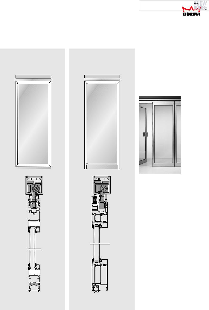
Panel types
In the case of the fully
glazed HSW-G / HSW-Midrange systems, the panels create a continuous, transparent surface without any lateral framing. For a more sophisticated or intricate appearance, singlepoint fixings (HSW-GP) are also available.
Example of an HSW-G system
Fully glazed with door rails
This folding system with top and bottom glazing rails coordinates perfectly with the HSW-G variant.
The FSW-G operates without a separate stacking area, and instead folds together within the main frontage or partition zone.
HSW-G / HSW-Midrange / FSW-G / FSW-C/C plus Fully glazed with door rails
HSW-G / HSW-Midrange /
FSW-G / FSW-C/C plus
Example of an FSW-G system
Hinge-linked door rails
ТЕХНИЧЕСКАЯ ИНФОТЕКА 

 www.know-house.ru/infotek/


HSW-GP |
HSW-GE BOXes |
|||||||||||||
Fully glazed |
Fully glazed |
|||||||||||||
with single-point |
with |
|||||||||||||
fixings |
patch fittings |
|||||||||||||
|
|
|
|
|
|
|
|
|
|
|
|
|
|
|
|
|
|
|
|
|
|
|
|
|
|
|
|
|
|
|
|
|
|
|
|
|
|
|
|
|
|
|
|
|
|
|
|
|
|
|
|
|
|
|
|
|
|
|
|
|
|
|
|
|
|
|
|
|
|
|
|
|
|
|
|
|
|
|
|
|
|
|
|
|
|
|
|
|
|
|
|
|
|
|
|
|
|
|
|
|
|
|
|
|
|
|
|
|
|
|
|
|
|
|
|
|
|
|
|
|
|
|
|
|
|
|
|
|
|
|
|
|
|
|
|
|
|
|
|
|
|
|
|
|
|
|
|
|
|
|
|
|
|
|
|
|
|
|
|
|
|
|
|
|
|
|
|
|
|
|
|
|
|
|
|
|
|
|
|
|
|
|
|
|
|
|
|
|
|
|
|
|
|
|
|
|
|
|
|
|
|
|
|
|
|
|
|
|
|
|
|
|
|
|
|
|
|
|
|
|
|
|
|
|
|
|
|
|
|
|
|
|
|
|
|
|
|
|
|
|
|
|
|
|
|
|
|
|
|
|
|
|
|
|
|
|
|
|
|
|
|
|
|
|
|
|
|
|
|
|
|
|
|
|
|
|
|
|
|
|
|
|
|
|
|
|
|
|
|
|
|
|
|
|
|
|
|
|
|
|
|
|
|
|
|
|
|
|
|
|
|
|
|
|
|
|
|
|
|
|
|
|
|
|
|
|
|
|
|
|
|
|
|
|
|
|
|
|
|
|
|
|
|
|
|
|
|
|
|
|
|
|
|
|
|
|
|
|
|
|
|
|
|
|
|
|
|
|
|
|
|
|
|
|
|
|
|
|
|
|
|
|
|
|
|
|
|
|
|
|
|
|
|
|
|
|
|
|
|
|
|
|
|
|
|
|
|
|
|
|
|
|
|
|
|
|
|
|
|
HSW-GP HSW-GE BOXes
22 |
04/09 |
|
|
|
|
|
|
|
|
|
|
|
|
|
ТЕХНИЧЕСКАЯ ИНФОТЕКА |
|
|
|
|
|
|
|
|
||
HSW / FSW |
|
|
HSW-R |
|
www.know-house.ru/infotek/ |
||
|
|
|
|
|
|
||
Panel Types |
|
HSW-ISO |
|
|
|
|
|
|
|
|
|
|
|
|
|
|
|
|
|
|
|
|
|
|
|
|
|
|
The all-round framing |
HSW-R |
|
|
|
|
|
|
|
|
provided on the individual |
||||
HSW-ISO |
|||||||||||||
Fully |
|
|
|
|
|
|
|
|
panels of an HSW-R system |
||||
Fully framed |
|||||||||||||
framed |
|
|
|
|
|
|
|
|
not only offers high stability |
||||
with double glazing |
|||||||||||||
|
|
|
|
|
|
|
|
|
|
|
|
|
but also an excellent barrier |
|
|
|
|
|
|
|
|
|
|
|
|
|
to keep out external |
|
|
|
|
|
|
|
|
|
|
|
|
|
influences. The panels can |
|
|
|
|
|
|
|
|
|
|
|
|
|
be constructed with |
|
|
|
|
|
|
|
|
|
|
|
|
|
laminated or toughened |
|
|
|
|
|
|
|
|
|
|
|
|
|
|
|
|
|
|
|
|
|
|
|
|
|
|
|
safety glass as required. |
|
|
|
|
|
|
|
|
|
|
|
|
|
|
|
|
|
|
|
|
|
|
|
|
|
|
|
|
|
|
|
|
|
|
|
|
|
|
|
|
|
|
Example of an HSW-R system
Fully framed
or HSW-ISO
Fully framed with thermalbreak frame profiles
|
|
|
|
|
|
|
|
|
|
|
|
|
|
|
|
|
|
|
|
|
|
|
|
|
|
|
|
|
|
|
|
|
|
|
|
|
|
|
|
|
|
|
|
|
|
|
|
|
|
|
|
|
|
|
|
|
|
|
|
|
|
|
|
|
|
|
|
|
|
|
|
|
|
|
|
|
|
|
|
|
|
|
|
|
|
|
|
|
|
|
|
|
|
|
|
|
|
|
|
|
|
|
|
|
|
|
|
|
|
|
|
|
|
|
|
|
|
|
|
|
|
|
|
|
|
|
|
|
|
|
|
|
|
|
|
|
|
|
|
|
|
|
|
|
|
|
|
|
|
|
|
|
|
|
|
|
|
|
|
|
|
|
|
|
|
|
|
|
|
|
|
|
|
|
|
|
|
|
|
|
|
|
|
|
|
|
|
|
|
|
|
|
|
|
|
|
|
|
|
|
|
|
|
|
|
|
|
|
|
|
|
|
|
|
|
|
|
|
|
|
|
|
|
|
|
|
|
|
|
|
|
|
|
|
|
|
|
|
|
|
|
|
|
|
|
|
|
|
|
|
|
|
|
|
|
|
|
|
|
|
|
|
|
|
|
|
|
|
|
|
|
|
|
|
|
|
|
|
|
|
|
|
|
|
|
|
|
|
|
|
|
|
|
|
|
|
|
|
|
|
|
|
|
|
|
|
|
|
|
|
|
|
|
|
|
|
|
|
|
|
|
|
|
|
|
|
|
|
|
|
|
|
|
|
|
|
|
|
|
07/08 |
|
|
|
|
|
|
|
|
|
|
|
23 |
||||