

Extension to reduction unit layout Slow speed (output) shaft.
Draw shaft diameter for the wheel of
(Fig.8)
Draw collar diameter of
 .
.
 (Fig.8)
Extension to reduction unit layout
(Fig.8)
Extension to reduction unit layout
3. Draw section of shaft for rolling bearing mounted to shaft end. Length of section shall be defined as per bearing width B
4. Draw section of shaft for
rolling bearing and compacting element – sleeve (symbol M in
Fig.8). The sleeve is fit within distance of
![]() mm
from outside bearing face end and its’ profile is marked only by
diagonal line with arrow. Length of the shaft section is to be set
mm
from outside bearing face end and its’ profile is marked only by
diagonal line with arrow. Length of the shaft section is to be set
![]() .
or it could be set as
.
or it could be set as
![]() мм.
мм.
5. Draw dimensions of shaft cylindrical end to be set as per GOST 12080-66.
High speed (input) shaft
Draw section of shaft between
inner end faces of bearings and pinion face end, shaft diameter value
to be set as
![]() .
.
Layout arrangement of this shaft is similar to low speed shaft.
2.6. General recommendations for the design of reduction unit housing elements
The housing is designed for installation of unit elements within it, lubrication of gears and bearing, as well as to protect parts from contamination and forces during reduction unit operation. The housing has to be robust and rigid, because deformation of the housing may cause shaft distortion that will lead to uneven distribution of load alongside the teeth length of gearing. In order to increase the rigidity of the housing, bearing sets are fit with pads and fins.
Housing parts have complicated shape and contain a lot of metal, therefore it’s recommended to manufacture housings using cast iron casting technique. Housings made of cast iron are capable of reducing noise and vibration.
For convenient mounting purposes the housing usually has split-design feature (refer to Fig.1). Horizontal type reduction units have splitting line alongside the shaft axle line. Lower part of housing is referred to as basis or housing and upper one as housing cover. Thickness of housing wall is the major design feature.

Figure 9. Extension to reduction unit layout.
Inner walls of the housing mate the radius . (Fig.9)
Thickness
of housing wall ![]() and
reduction unit cover wall
and
reduction unit cover wall
![]()
of single-step cylindrical reduction unit may be calculated from the following equations:
![]() mm;
mm; ![]() mm.
mm.
The values calculated to be rounded to integers.
Thickness
of fins ![]() mm.
mm.
Mounting
of housing to the basis is carried out with threaded elements.
Diameter of foundation bolts is calculated with the following
equation ![]() mm.
mm.
Mounting of cover to reduction unit housing is performed with tie bolts (Fig.6). Diameter of tie bolts is as follows:
for bearings
 mm;
mm;for connecting foundation with cover
 мм.
мм.
Width of facet has to be sufficient to provide space for bolt head
![]() mm.
mm.
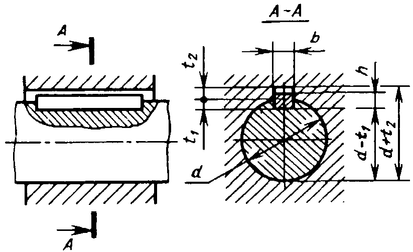
2.7. Selection of tab
In order to transmit torque from shaft to nave (or vice versa) and fixation of elements on the shaft the tab feature is used.
The main connecting element is tab to be fit into a slot of a shaft and a part to be connected. The sizes of tabs are standardized. Generally, prismatic tabs of GOST 22360-78 of are applied
The
dimensions ![]() ,
,
![]() ,
,
![]() of standard prismatic tab and depth
of standard prismatic tab and depth ![]() of tab slot in the shaft are selected subject to shaft diameter and
gear nave length as per GOST 22360-78 (table 8).
of tab slot in the shaft are selected subject to shaft diameter and
gear nave length as per GOST 22360-78 (table 8).
Table8.
Prismatictabs(perGOST22360-78)
|
Shaft diameter d, mm |
Tab
cross-section
|
Slotdepth,mm |
Facet for tabs, mm
|
length
| |
|
Shaft
|
Nave
| ||||
|
From 12 to 17 |
55 |
3 |
2,3 |
0,25…0,4 |
10-56 |
|
From17 to 22 |
66 |
3 |
2,8 |
14-70 | |
|
From.22 to 30 |
87 |
4 |
3,3 |
18-90 | |
|
From.30 to 38 |
108 |
5 |
3,3 |
0,4…0,6 |
22-110 |
|
From 38 to 44 |
128 |
5 |
3,3 |
28-140 | |
|
From 44 to50 |
149 |
5,5 |
3,8 |
36-160 | |
|
From.50 to 58 |
1610 |
6 |
4,3 |
45-180 | |
|
From.58 to 65 |
1811 |
7 |
4,4 |
50-200 | |
|
From.65 to 75 |
2012 |
7,5 |
4,9 |
0,6…0,8 |
56-220 |
|
From 5 to 85 |
2214 |
9 |
5,4 |
63-250 | |
|
From 5 to 95 |
2514 |
9 |
5,4 |
70-280 | |
Note:
Example of tab symbol with dimensions of ![]() mm,
mm,
![]() mm,
mm,
![]() mm:
mm:
1811100 GOST 23360-78 tab
Tab length
as of ![]() mm
is taken from standard values taking into account the dimensions of
cross-sections
mm
is taken from standard values taking into account the dimensions of
cross-sections ![]() and
and![]() .
.
Work
tab
length is as follows: ![]() .
.
|
After
selecting tab dimensions the test calculation of tab connection
for side surface distortion strength rigidity (Fig.10) with work
tab length and rounded edges of |
Fig.10. Calculation scheme of prismatic tab connection
|
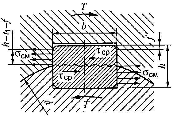
Condition
for distortion strength![]() ,
,
![]() –permissible
distortion stress for tab connections with steel nave
–permissible
distortion stress for tab connections with steel nave ![]() MPa
MPa