

1.2.2. Graphic portion of the course work
The graphic portion of the work shall contain the following:
assembly drawing of output shaft unit on A3 format sheet;
data sheet for the unit assembly drawing, compiled on separate A4 format sheets.
1.3. Selection of task for the course work
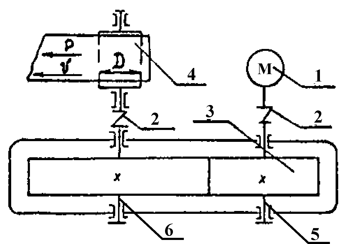
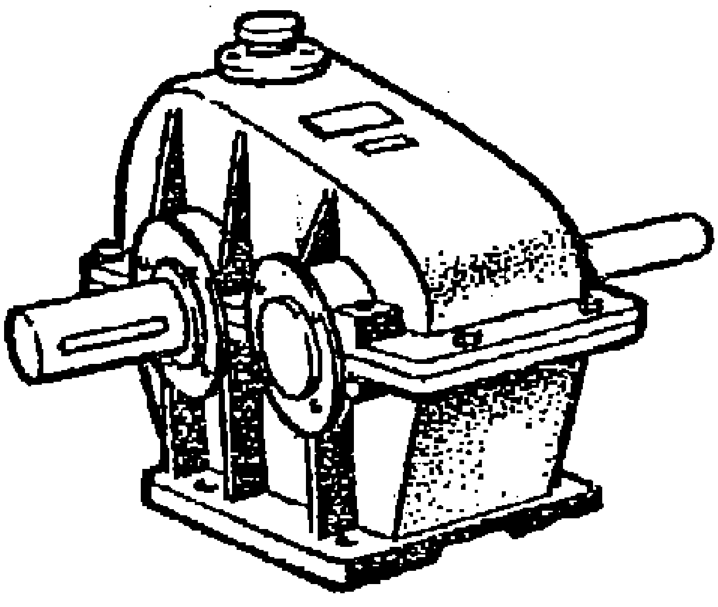
A drive unit – is a device, including power source (electric motor 1, Figure 1) and a transmission mechanism (single-reduction unit) which serves to engage actuation mechanism 4. Couplings 2 serve to connect rotating shafts and to transmit the torque. The gear reduction unit is reviewed as a transmission mechanism herein.
Reduction unit is a toothed gearing to be mounted within sealed housingand serves to reduce frequency of rotation and increase the torque. Within reduction units the helical bevel gears are applied having high load-bearing capacity and smoothness. Scheme of the drive unit and general view of the reduction unit are outlined on Figure 1. The term “single reduction” specifies the number of gears .
|
|
|
|
|
Figure 1. Scheme of the drive unit and general view of the reduction unit | ||

For the design work the benchmark data is as follows:
capacity
 at outlet shaft;
rotational frequency
 of outlet shaft;
gear ratio
 of the drive unit.
The option of benchmark data for the design work is to be selected from Table 1 as per the last two digits of Test book number 21012/05.
Table 1.
The options of benchmark data for the design work
|
А |
|
В |
|
|
Hardness option of gear as per Table 5 |
|
0 |
2,0 |
0 |
230 |
3,15 |
1 |
|
1 |
2,8 |
1 |
230 |
4 |
2 |
|
2 |
3,7 |
2 |
260 |
3,15 |
3 |
|
3 |
5,0 |
3 |
260 |
5 |
4 |
|
4 |
7,0 |
4 |
250 |
4 |
5 |
|
5 |
2,0 |
5 |
280 |
5 |
1 |
|
6 |
2,8 |
6 |
300 |
3,15 |
2 |
|
7 |
3,7 |
7 |
300 |
4 |
3 |
|
8 |
5,0 |
8 |
310 |
3,15 |
4 |
|
9 |
7,0 |
9 |
320 |
4 |
5 |
2. Guidelines of calculation portion of the course work
2.1. Electric-motor selection
The main benchmark data for electric-motor selection is as follows:
outlet drive shaft capacity
 ;
;outlet drive shaft rotational frequency
 .
.
Electric-motor
power requirements: ![]() ,
,
where ![]() – totalefficiencyof
reduction unit;
– totalefficiencyof
reduction unit;
![]() –number
of bearings.
–number
of bearings.
Furthermore,
due to the lack of additional gears in the drive, then ![]() ,
where
,
where ![]() – transmission
ratio of a gear.
– transmission
ratio of a gear.
Recommended
values of toothed gear ![]() and bearings
and bearings ![]() are outlined on Figure 2.
are outlined on Figure 2.
Figure 2.
Gear and bearings efficiency
|
Transmission components |
Average
value
|
|
Toothed gear |
0,96…0,98 |
|
Rolling bearings (one pair) |
0,99 |
Electric-motor rotational frequency:
![]() .
.
Electric-motor rated capacity is to be:
![]() .
.
Rated capacity is the capacity that electric motor is capable to produce continuously without overheating above permissible temperature.
In general machine building industry three-phase short closed asynchronous motors of 4A series (4 stands for serial number of series; A stands for asynchronous type of the motor) are used. (Table 3).
Table 3.
Rated capacity and rotational frequency of 4A type motors.
|
|
Synchronous frequency, revs per minute | |||
|
3000 |
1500 |
1000 |
750 | |
|
0,75 |
4А71А2/2840 |
4А71B4/1390 |
4А80A6/915 |
4А90LA8/700 |
|
1,1 |
4А71В2/2810 |
4А80A4/1420 |
4А80B6/920 |
4А90LB8/700 |
|
1,5 |
4А80А2/2850 |
4А80B4/1415 |
4А90L6/935 |
4А100L8/700 |
|
2,2 |
4А80В2/2850 |
4А90L4/1425 |
4А100L6/950 |
4А112MA8/700 |
|
3 |
4А90L2/2840 |
4А100S4/1435 |
4А112MA6/955 |
4А112MB8/700 |
|
4 |
4А100S2/2880 |
4А100L4/1430 |
4А112MB6/950 |
4А132S8/720 |
|
5,5 |
4А100L2/2880 |
4А112M4/1445 |
4А132S6/965 |
4А132M8/720 |
|
7,5 |
4А112M2/2900 |
4А132S4/1455 |
4А132M6/970 |
4А160S8/730 |
|
11 |
4А132M2/2900 |
4А132M4/1460 |
4А160S6/975 |
4А160M8/730 |
|
15 |
4А160S2/2940 |
4А160S4/1465 |
4А160M6/975 |
4А180M8/730 |
Note.
To make the
above table more indiscrete after the slash the rated speed ![]() (rpm) is indicated that is not included into the motor symbol.
(rpm) is indicated that is not included into the motor symbol.
The following parameters are to be included into the explanatory note for this type of the motor. motor symbol;
rated capacity
 ,
кВт;
,
кВт;speed under rated load
 ,
rpm.
,
rpm.