

2.2. Reduction unit kinematical and capacity calculations.
Rotational frequency of drive shafts:
high speed shaft
 ;
;low speed shaft
 .
.
Angular speeds of drive shafts:
inlet
 ;
;outlet
 .
.
The following ratios between torques on the shafts are used for transmission calculation
![]() ,
hence,
,
hence,![]() .
.
Drive
shaft torque, at ![]() :
:
 –it’s
direction matches the direction of the shaft rotation, i.e. it’s a
torque of moving forces
–it’s
direction matches the direction of the shaft rotation, i.e. it’s a
torque of moving forces  –Its
direction is oppose to shaft rotation, i.e. it’s a torque of
resisting forces
–Its
direction is oppose to shaft rotation, i.e. it’s a torque of
resisting forces
Results of design work are to be outlined in Table 4
Table4.
Reduction unit characteristics
|
Characteristics |
Shaft 1 |
Shaft 2 |
|
Rotational frequency, r/min |
|
|
|
Angular speed, R/s |
|
|
|
Torque, Newton per meter |
|
|
2.3. Toothed gear drive calculation
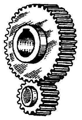
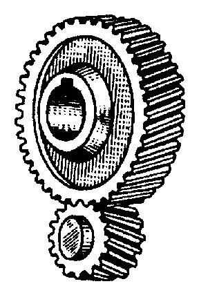
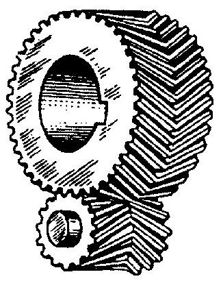
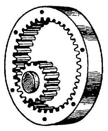
Gear drives are mechanisms transmitting a movement with the assistance of gears. The gears are parts (cylinders) having evenly located teeth (cogs) and gashes (Fig. 2).
Pinion- is a smaller of two interacting gears,
and wheel – is a larger of the two interacting gears.
|
а) |
б) |
в) |
г) |
|
Fig. 2. Basic types of cylindrical gears. External gears: spur (а); helical (б); double helical (в). internal gear (г) | |||
2.3.1. Assessment of permissible stresses
Hardness of gear wheels should be selected subject to application and conditions of transmission operation. In our coursework we use carbon and alloyed steels subjected to heat treatment, allowing to ensure required hardness under given thickness of the part blank .
Table 5.
Options of gear hardness
|
Option |
wheel |
pinion | ||
|
hardness |
GOST 8479-70 |
hardness |
GOST 8479-70 | |
|
1 |
212…248 НВ |
S490 (655) |
248…293 НВ |
S640 (785) |
|
2 |
223…262 НВ |
S540 (685) |
262…311 НВ |
S685(835) |
|
3 |
235…277 НВ |
S590 (735) |
277…321 НВ |
S735 (880) |
|
4 |
248…293 НВ |
S640 (785) |
293…331 НВ |
S785 (930) |
|
5 |
235…277 НВ |
S590 (735) |
277…321 НВ |
S735 (880) |
|
Note: GOST 8479-70 define forging features; symbols:
S – type
of strength; number in three digits – yield stress
value
| ||||
In the coursework the gear hardness option is defined by its benchmark data. (Table1).
The selection of hardness of pinion and wheel should be carried out as per the following rule: maximum limit of wheel hardness should comply with minimum limit of pinion hardness.
Permissible stresses are assessed for the following conditions:
continuous operation under constant load;
helical gear;
part blank- forging;
heat treatment of gear wheels – improvement (hardening with further high temperature tempering).
Permissible stresses for surface load durability
|
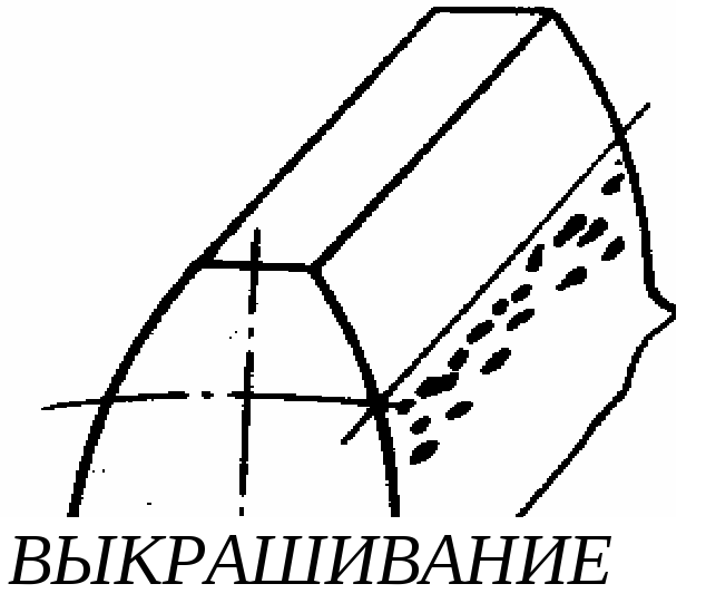
CHIPPING |
This type of calculation exclude fatigue chipping of teeth surfaces, the main reason for teeth surface rapture. |
Permissible surface stresses for transacting gears are calculated as follows:
![]() ,
МPs
,
МPs
где ![]() ,
, ![]() ;
;
![]() –average
hardness value;
–average
hardness value;
![]() –safety
ratio for homogeneous material structure.
–safety
ratio for homogeneous material structure.