

Лекция Неотл ЭХОКГ / Emergency Echocardiography
.pdf14 GETTING READY FOR THE STUDY
manually, by lowering the MI, or by using the machine built-in setup for contrast studies. The contrast agent is prepared following the manufacturer’s instructions and, generally, given as a bolus through an antecubital vein using a cannula with a 20G lumen and avoiding valved ports or side arms. The injection is followed by flushing with normal saline. In a typical sequence, a preset protocol is used where the mechanical index is lowered when the contrast starts to fill the right side to allow enough time for optimal visualization without rapid bubbles destruction.
1.7.1 Safety Profile, Indications, and Contraindications (Table 1.2)
Mild and transient side effects such as headache, parestesias, back pain, or mild allergic reactions are occasionally described but serious adverse events are very rare (0.01%), so the overall safety profile is excellent. However, following reports of a few deaths cases after contrast studies in patients with severe, acute cardiopulmonary conditions, the European Medicines Agency (EMEA) in 2004 introduced limitations for the use of SonoVue
TABLE 1.2. Contrast echocardiography: general indications and contraindications.
Indications:
•Improve LV function assessment if
°≥ 2 segments not well visualized
•Improve definition of LV structures
°LV thrombus
°Pseudoaneurysm
°Apical or noncompaction CMP
°LV tumor
•Enhance Doppler signal of aortic stenosis
Contraindications:
•Known intracardiac shunts
•Previous allergic reaction to the agent
•Ongoing or recent acute or unstable cardiac conditions*
°Unstable angina/acute coronary syndrome
°Acute or severe cardiac failure
°Complex ventricular arrhythmia or at risk for QT prolongation arrhythmia
•Suspected or likely pulmonary vascular disease*
°Severe emphysema
°Pulmonary embolism
°ARDS
CMP cardiomyopathy *see text below

1.8 CONTROLS AND SETTINGS - PRACTICAL TIPS 15
in Europe and the Food and Drugs Administration (FDA) in 2007 required a boxed warning for the use of perfluoropropane agents (Luminity, Optisone) in the United States. Also the patients were to be monitored during the study and for 30 min thereafter. To which extent these major events were related to the use of contrast agents is debatable since they occurred in unstable and high-risk patients. These contraindications have been removed by the FDA in 2008, though the warning of possible severe reactions and the need for 30 minutes monitoring in high risk patients are maintained.
1.8 CONTROLS AND SETTINGS - PRACTICAL TIPS
•Decide on:
°Transducer frequency
■Low frequencies for overweight, big-chest, emphysematous patients
■High frequencies for young, thin-chest individuals
°Fundamental versus second harmonic imaging
■Second harmonic imaging is preferred as a rule
•2D Adjustments and settings
°Depth of field
■A good routine is to use more depth to get a general view and then, if necessary, reduce it to accommodate the area of interest.
°TGC
■Modern machines have built-in automatic TGC but also offer manual fine-tuning with a group of levers which control the differential amplification of the reflected ultrasound according to the tissue depth at which it originates. In a typical configuration, there is a gradual increase in amplification from nearto distal field.
°Sector width and position
■The narrower the scan sector is the better the image. Use a wide sector to get a general view and then narrow on your area of interest.
•Spectral Doppler adjustments and settings
°Decide on:
■PW to localize the site of flow acceleration
■CW to display high velocities
°Adjust baseline and scale to fit the displayed velocity (Fig. 1.4).

16GETTING READY FOR THE STUDY
°Consider using high-speed sweep velocities (100 cm/s) for better detailing of the waveform and lower velocities (25 cm/s) to assess phasic changes (i.e., mitral flow respiratory variations in tamponade)
°If necessary, use color Doppler for optimal positioning of the PW sample volume or CW line, then turn color off to increase the frame rate.
•Color Doppler adjustments and settings
°Use a gain level that will give full color display without painting areas devoid of flow (extracardiac, nonflow regions)
°Use a scale (Nyquist limit) in the range of 50–60 cm/s for routine qualitative color imaging (Fig. 1.5)
°Use the B/W suppress function to eliminate 2D imaging out of the color sector
°Narrow the sector to your area of interest.
•General:
°Have a good ECG tracing for cardiac cycle events timing and for digital capture.
°Liberally use varying depths of field, sector widths, and zooming to improve image quality and anatomical detail. 2D visualization should be done first followed by color and spectral Doppler imaging if appropriate.
°For TEEs and studies in emergencies, tape and/or acquire everything: you may not have the chance to repeat the study.
1.9 ARTIFACTS
Artifacts can represent a diagnostic challenge even for the experienced echocardiographer. It is not unusual for TEE or magnetic resonance imaging (MRI) studies to be requested because of artifactual echo findings.
The most frequently encountered artifacts are as follows:
•Near-field noise artifacts (Fig. 1.9)
°These are seen as a clutter of echoes in the LV apex. Occasionally, they are misdiagnosed as apical masses.
•Reverberation artifacts (Figs. 1.10–1.11)
°Are related to strong reflectors such as prosthetic valves, ribs, or pericardium. Generally, they appear as either linear echoes, which are occasionally confused with a pathological structure such as an intimal flap, or a foreign body, or as multiple echoes extending from the target structure into the far field. Occasionally, the reflected ultrasound is bounced back and forth between the transducer and the

1.9 ARTIFACTS 17
FIG. 1.9. Typical near-field artifact (arrows) mimicking a small protruding thrombus in apical 4-chamber view. In this case, the diagnosis was even more problematic since severe left ventricle systolic dysfunction was present. However, the overall appearance and lack of mobility as compared with the heart motion and a slight change in a near-field time-gain-compensation (TGCs), proved this to be an artifact.
target, creating “ghosting” images, where two identical structures coexist in the same view.
•Side lobes artifacts
°Strong reflectors at the periphery of the ultrasound beam can be displayed as originating within the main beam, so an existing structure appears or generates echoes in an unusual location.

FIG. 1.10. Reverberation artifact, most probably due to a rib. A linear echogenic finding seems to be present in the LV cavity, below the MV in this subcostal view. Besides the unusual appearance, during real-time inspection of the acquired sequence, there was no relationship between this finding and the motion of the heart. MV mitral valve, TV tricuspid valve, LV left ventricle.
FIG. 1.11. Typical reverberations artifact appearing as multiple echoes (thin arrows) obscuring structures behind an aortic mechanical prosthetic valve (thick arrows).

1.10 STANDARD VIEWS IN TRANSTHORACIC ECG 19
1.9.1Clues to Avoid and Recognize Artifacts
•Use lower power settings and harmonic rather than fundamental imaging to reduce the odds of artifacts formation
•Think of an artifact whenever:
°The image does not make sense
°The overall appearance is unusual
°The finding seems to be within the heart cavities or attached to a wall but does not move with the heart and has no motion of its own
°It is at a distance from the transducer which is twice the one from the transducer to a highly echogenic structure
°It is seen in one view only
•If an artifact rather than a true finding is suspected:
°Lower the gains
°Change the transducer frequency
°Slightly change the transducer orientation
°Look for a strong reflector that could explain artifact formation
°Consult an experienced colleague
1.10 STANDARD VIEWS IN TRANSTHORACIC ECHOCARDIOGRAPHY
The standard views in transthoracic echocardiography are grouped in parasternal, apical, subcostal, and suprasternal views according to the position of the transducer. Ideally, the patient should be positioned in left lateral decubitus for the parasternal and apical views and lying on his back for the subcostal and suprasternal views. In unstable patients or during cardiopulmonary resuscitation (CPR), only one or two views (subcostal and, if possible, apical) should be attempted to immediately rule out critical pathologies, otherwise all views should be attempted.
Transoesophageal views are discussed in Sect. 2.2.
1.10.1 Parasternal Views (Figs. 1.12–1.18)
Parasternal views are obtained with the transducer located immediately to the left of the sternum, generally in intercostal spaces 3–5 depending on body habitus. The imaging plane, as specified by the marker on the transducer is aligned with the long axis of the ventricle for the parasternal long-axis (PSLA) view and then rotated at 90° and tilted from the base toward the apex to obtain the parasternal short-axis (PSSA) views of the heart. By convention, the heart is displayed oriented with the apex toward the left side of the screen.
1.10.2 Apical Views (Figs. 1.18–1.21)
Apical views are obtained by positioning the transducer at the apex, which can be either “looked for” in the fifth intercostal space or located by palpation. The heart is displayed with the
20 GETTING READY FOR THE STUDY
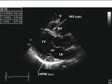
FIG. 1.12. End-diastolic frame in parasternal long-axis view, with identification of main anatomical structures and of coronary perfusion territories. Two-dimensional measurements for LV thickness and dimensions are also displayed. The closed aortic valve is seen as a fine line in the aortic root (small arrows). Note the nonspecific finding of strong and apparently thick pericardial reflection beyond the posterior wall in this normal subject without any suspicion of pericardial pathology. DA descending aorta, IVS interventricular septum, LA left atrium, LAD left anterior descending coronary artery, Lcx left circumflex coronary artery, LVPW left ventricular posterior wall.
apex toward the upper field of the screen, though some institutions use a reversed, more “true-to-anatomical orientation” display. To avoid foreshortening, a good technique is to move the transducer downwards and leftwards until the apex is lost, and then bring it back, until the apex is identified again. Rotation of the transducer counterclockwise will display first the apical 2-cham- ber and then the apical long-axis view.
1.10.3 Subcostal View (Fig. 1.22)
For this view, the transducer is positioned beneath the xyphoid appendix. Having the patient bend his knees to relax the abdominal wall and take a deep breath to flatten the diaphragm and lower the heart will improve the image. This view is of special importance in critically ill patient, since it may be the only available transthoracic view. In emergencies, it can rapidly confirm or rule out pericardial effusion or severe right ventricle (RV) enlargement suggestive of massive pulmonary embolism. It also allows

FIG. 1.13. Diastolic frame in PSLA view modified for the right ventricle inflow tract. The view is obtained starting from the standard PSLA view (Fig. 1.12) and tilting the transducer opposite to the left shoulder. May be the best available view for the tricuspid valve (anterior and posterior leaflets) and tricuspid regurgitant jet. RA right atrium, TV tricuspid valve, PSLA parasternal long axis.
FIG. 1.14. Diastolic frame in PSLA view modified for the pulmonic valve and the main pulmonary artery. The view is obtained starting from the standard PSLA view (Fig. 1.12) and tilting the transducer toward the left shoulder. This view is not mandatory but it may complement the PSSA, basal-level view (Fig. 1.15). PV pulmonic valve, RVOT right ventricular outflow tract, PSSA parasternal short axis.

22 GETTING READY FOR THE STUDY
FIG. 1.15. Diastolic frame in PSSA view, basal level. The view allows simultaneous inspection of the aortic, pulmonic and tricuspid valve, interatrial septum, right ventricular outflow tract, and main pulmonary artery. LCC left coronary cusp, NCC noncoronary cusp, RCC right coronary cusp, IAS interatrial septum, PSSA parasternal short axis.
FIG. 1.16. Diastolic frame in PSSA at MV level showing the mitral leaflets in open position. The anterolateral and posteromedial commissures are positioned at 3 o’clock and 9 o’clock, respectively. AML anterior mitral leaflet, PML posterior mitral leaflet, PSSA parasternal short axis, MV mitral valve.

1.10 STANDARD VIEWS IN TRANSTHORACIC ECG 23
FIG. 1.17. End-systolic frame in PSSA view at papillary muscles level. The white lines mark the approximate boundaries between LV wall segments and their coronary supply, starting clockwise from a 9 o’clock position. IVS (LAD) left ventricular anterior wall (LAD), left ventricular lateral wall (Lcx), LVPW (PDA), left ventricular inferior wall (PDA), APM anterolateral papillary muscle, PDA posterior de-scending coronary artery, PPM posteromedial papillary muscle, PSSA parasternal short-axis.
FIG. 1.18. End-systolic frame in apical 4-chamber view. The LV walls are identified with the corresponding coronary supply. The hachured area marks the basal inferior IVS which is vascularised by the right coronary artery. Note the very thin midportion of the interatrial septum (fossa ovalis area), which occasionally can be mistaken as a septal defect. LVLW left ventricular lateral wall, IVS interventricular septum.