

INSTITUTE OF PHYSICS PUBLISHING |
NANOTECHNOLOGY |
Nanotechnology 16 (2005) 1793–1797 |
doi:10.1088/0957-4484/16/9/064 |
Polymer/nanoporous silica nanocomposite blue-light-emitting diodes
Jong Hyeok Park1, Sungwook Kim2, Young Chul Kim3,4 and
O Ok Park1,4
1Department of Chemical and Biomolecular Engineering, Korea Advanced Institute of Science and Technology, 373-1 Guseong-dong, Yuseong-gu, Daejeon 305-701, Korea
2Department of Chemistry and Biochemistry, The University of Texas at Austin, Austin, TX 78712, USA
3Materials Research Center for Information Display, College of Environment and Applied Chemistry, Kyung Hee University, Yongin, Kyunggi-do 499-701, Korea
E-mail: kimyc@khu.ac.kr (Y C Kim) and ookpark@kaist.ac.kr (O O Park)
Received 27 April 2005, in final form 5 June 2005
Published 18 July 2005
Online at stacks.iop.org/Nano/16/1793
Abstract
The use of polymer light-emitting devices is hindered by their poor stability on exposure to oxygen and moisture as well as by their low quantum efficiency. In the case of blue-light-emitting polymers, an additional major concern is the presence of long-wavelength tails in their emission spectra. With the aim of simultaneously overcoming all these drawbacks, a blue-light-emitting polymer/mesoporous silica nanocomposite was prepared by blending poly(9,9-dioctylfluorene) with nanosized MCM-41. This nanocomposite film shows dramatically increased photostability and colour purity, as well as higher electroluminescence output.
1. Introduction
Light-emitting diodes (LEDs) that incorporate conjugated polymers as the active layer have undergone rapid improvement since the discovery of electroluminescence (EL) from poly( p-phenylenevinylene) (PPV) [1], with specifications now approaching industrial standards [2]. The 9,9-disubstituted polyfluorenes (PFs) are among the most promising candidates. PFs have been used to demonstrate relatively high photoluminescence (PL) and EL quantum efficiencies and high EL brightness among various polymeric materials [3, 4]. Moreover, as a host material, PFs enable full colour via conjugated polymers and with phosphorescent dyes [5–7].
Despite the ongoing improvements, however, in terms
of the stability of polymer |
LEDs |
(PLEDs) fabricated |
from PF-type materials, the |
lifetime |
and colour purity |
need improvement for the commercialization of full-colour displays [8, 9]. Photo-oxidation plays an important role in the lifetime of PLEDs fabricated from PFs [10]. In addition, most of these PLEDs suffer from a degradation of the device under operation; the degradation is documented in the formation
4 Authors to whom any correspondence should be addressed.
of a low-energy emission band at 2.2–2.3 eV, which turns the desired blue emission colour into an undesired bluegreen emission. These long-wavelength tails become more pronounced upon exposure to heat (for example, the Joule heat generated during the operation of LEDs) [11, 12].
Here we report on the dramatic effects of polymer chain
isolation on the |
enhancement of the photonic properties |
of blue-emitting |
polymers, with promising implications |
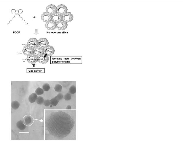
for the commercialization of blue-emitting devices based on conjugated polymers. The dielectric walls of MCM41 might simultaneously solve all the above-mentioned serious problems of blue-emitting polymers, as illustrated in figure 1(a). First, organic/inorganic nanocomposite materials with a three-dimensional geometry and good barrier properties can prevent photo-oxidation by blocking the penetration of oxygen. The nanocomposite materials can also reduce ketotype defects which emit non-pure blue light. Second, the nanocomposite materials can enhance emission stability at high temperature. Third, the EL light output of the luminescent polymer is also greatly enhanced by the reduction in interchain interactions.
Recently, the energy transfer characteristics of conducting polymers embedded in the channels of oriented, hexagonal nanoporous silica have been obtained [13, 14]. However,
0957-4484/05/091793+05$30.00 © 2005 IOP Publishing Ltd Printed in the UK |
1793 |
J H Park et al
(a)
50nm
(b)
Figure 1. (a) Schematic molecular structure of the PDOF/nanoporous silica nanocomposites. (b) TEM image of the synthesized MCM-41.
the use of this polymer/nanoporous silica in a PLED has not been reported because general MCM-41 has submicron particle size. Nanostructured composite materials consisting of PFs and organophilic-treated MCM-41 with particle size50 nm are the focus of this study. The type of PF/MCM-41 nanocomposite materials used in this study can be applied to the emitting layers of typical conjugated polymer-based LEDs with about 100 nm thickness.
2. Experimental details
Poly(9,9 -dioctylfluorene) (PDOF) was purchased from the American Dye Sources Co., and used without further purification. The MCM-41 with particle size 40 nm was synthesized using cetyltrimethylammonium bromide as the surfactant and tetraethylorthosilicate as the silica source [15]. First, 2 g of cetyltrimethylammonium bromide was dissolved in 970 g of 1.45 × 10⁻² M NaOH. Then, 9.3 g of tetraethylorthosilicate was slowly added to this solution at 80 ◦C, and the resulting mixture was stirred at 80 ◦C for 2 h. The silica product was filtered, washed with distilled water, and calcinated at 823 K.
MCM-41 was organically modified with trimethylchlorosilane [16]. To improve dispersion, it was also sonicated for 1 h in trichloroethylene before use. The solution of PDOF in trichloroethylene was mixed with the MCM-41 solution and then sonicated for 3 h to enable nanocomposite formation. We varied the weight ratios of MCM-41 to PDOF in the range 0.5–2.0, obtaining pure PDOF (0% MCM-41 by weight), PDOF1/MCM0.5 (33% MCM-41 by weight), PDOF1/MCM1 (50% MCM-41 by weight) and PDOF1/MCM2.0 (66% MCM41 by weight).
The PL spectra were measured while exciting specimens at 380 nm using a dual grating monochromator (Spex 270 M) with a photomultiplier tube (Hamamatsu R928) as a detector. The PL decay characteristics of the pristine PDOF film and of the PDOF/MCM-41 nanocomposite films were measured as a function of time during excitation by the strong monochromatic 380 nm light of a xenon lamp in air.
PLEDs composed of PDOF or PDOF1/MCM-41 nanocomposite layers were fabricated as follows. PEDOT/PSS films were spin cast from isopropyl alcohol onto indium–tin oxide (ITO)-coated glass substrates. Emissive layers with 120 nm thickness were spin-coated from trichloroethylene solutions onto the PEDOT/PSS layer. Finally, using thermal evaporation, the 1 nm thick LiF was deposited and then the 150 nm thick Al cathode was deposited under a pressure of ≈10−5 Torr. The electrical and luminescence characteristics of the devices were measured by using a current/voltage source measurement unit (Keithley 236) and a calibrated silicon photodiode in an integrating sphere.
XRD patterns were recorded by using a Rigaku multiflex diffractometer equipped with Cu Kα radiation (40 kV, 50 mA). Transmission electron microscopic (TEM) specimens were prepared by dropping the solution on a copper grid. Brightfield images were obtained with a JEOL JEM-2010 TEM operating at 200 kV.
3. Results and discussion
A transmission electron micrographs image of the synthesized MCM-41 nanoparticles is shown in figure 1(b). Generally, the x-ray diffraction (XRD) pattern for ordered nanoporous materials is composed of distinct diffraction limes appearing at low angles (typically, where 2θ < 5◦ ), which are used for determining the structure. These XRD lines decrease in intensity as guest species are loaded in the nanopores, and the intensity change is a useful means of judging the location of the guest species [17]. Similarly to most cases, our nanocomposite materials exhibited a decrease in the diffraction intensity (not shown). From the XRD behaviour, we concluded that PDOF/MCM-41 nanocomposite materials were prepared successfully by the method of mixing the solution.
In UV–vis absorption spectra, the PDOF/MCM-41 nanocomposite films showed nearly similar spectra compared with that of neat PDOF film. Light scattering in the nanocomposite films was not observed because the particle size is smaller than light wavelength. Figure 2 shows the normalized PL spectra of the PDOF and PDOF/MCM-41 nanocomposite films. The excitation at 380 nm was performed at a 45◦ angle to the thin film plane, and emissions were detected at a right angle with respect to the direction of the
1794
Polymer/nanoporous silica nanocomposite blue-light-emitting diodes
|
1.0 |
|
|
|
|
|
|
|
|
(a.u.) |
0.8 |
|
|
|
|
|
|
|
|
0.6 |
|
|
|
|
|
|
|
|
|
intensityPL |
|
|
|
|
|
|
|
|
|
0.4 |
|
|
|
|
|
|
|
|
|
|
|
|
|
|
|
|
|
|
|
|
0.2 |
|
|
PDOF |
|
|
|
|
|
|
|
|
PDOF1/MCM0.5 |
|
|
|
|||
|
|
|
|
|
|
|
|||
|
|
|
|
PDOF1/MCM1.0 |
|
|
|
||
|
0.0 |
|
|
PDOF1/MCM2.0 |
|
|
|
||
|
|
|
|
|
|
|
|
|
|
|
380 |
400 |
420 |
440 |
460 |
480 |
500 |
520 |
540 |
Wavelength (nm)
Figure 2. Normalized photoluminescence (PL) spectra of the PDOF and PDOF/MCM-41 nanocomposite films.
excitation beam. In contrast with the PL spectrum of the PDOF film, the PL spectra of the composite films are red-shifted and have decreased line widths. We attribute these effects to the beta phase formation of PDOF molecules in the MCM-41 nanopore [18, 19]. Because the beta phase has more extended conjugation than the glassy phase, excited states of the beta phase are red-shifted and have higher polarizability [18].
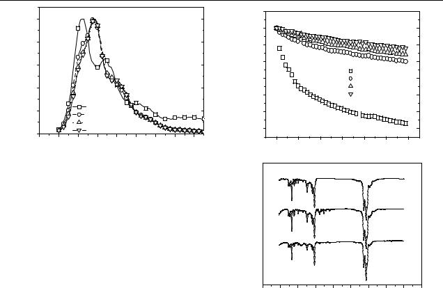
Figure 3 shows the changes in the PL intensities of the PDOF1/MCM0.5, PDOF1/MCM1.0, PDOF1/MCM2.0 and pure PDOF films as a function of time during excitation by the strong monochromatic 380 nm light of an xenon lamp in air. The PL intensities of the composite films decrease more slowly than that of pure PDOF film. When oxygen penetrates the films, it accelerates photo-oxidation and photodegradation, resulting in poor quantum efficiency [20]. This phenomenon implies that the excitons in the PDOF within the pores of MCM-41 possess better environmental stability with respect to oxygen and other detrimental substances in the atmosphere, resulting in a slower photodegradation process [21].
FTIR spectroscopy was used to probe any changes in the chemical structure that resulted from UV irradiation in air [10]. Figure 3(b) shows the infrared spectrum of thin films of the PDOF, with and without UV exposure in air. In photodegraded PDOF film and nanocomposite film, two new bands appear around 1717 and 1606 cm−1. The first band is consistent with a carbonyl stretch of an aromatic ketone or ester, and the second band may be interpreted as the stretching mode of an asymmetrically substituted benzene ring [22]. The intensity of the two peaks, which resulted from photooxidation, is more obviously noticeable in the PDOF film than in the nanocomposite film.
Recently, many researchers found that the low-energy emission band in PF-type polymers stems from keto-type defects which emit light and form due to degradation of the polymer [10]. In figure 2, the PL spectra of the PDOF/MCM41 nanocomposite films are obviously narrower than those of the PDOF film, and the formation of long-wavelength tails (around 490 and 540 nm) is significantly reduced. These improvements in the PL spectrum correspond to a purer blue emission, and can be attributed to the reduced number of keto defect sites produced by the walls of MCM-41 acting as an
(a) |
1.1 |
|
|
|
|
|
|
1.1 |
|
1.0 |
|
|
|
|
|
|
1.0 |
(a.u.) |
0.9 |
|
|
|
|
|
|
0.9 |
|
|
|
|
|
|
|
|
|
intensity |
0.8 |
|
|
|
|
|
|
0.8 |
0.7 |
|
|
|
PDOF |
|
|
0.7 |
|
|
|
|
PDOF1/MCM0.5 |
|||||
|
|
|
|
PDOF1/MCM1.0 |
|
|||
peak |
|
|
|
|
|
|||
0.6 |
|
|
|
PDOF1/MCM2.0 |
0.6 |
|||
0.5 |
|
|
|
|
|
|
0.5 |
|
PL |
|
|
|
|
|
|
||
|
|
|
|
|
|
|
|
|
|
0.4 |
|
|
|
|
|
|
0.4 |
|
0 |
500 |
1000 |
1500 |
2000 |
2500 |
3000 |
|
|
Time (s) |
|
(b) |
|
|
Transmittance |
a |
|
b |
||
|
||
|
c |
0 500 1000 1500 2000 2500 3000 3500 4000 4500
Wavenumber (cm-1)
Figure 3. (a) Decay of PL intensity of the pristine PDOF film and of the PDOF/MCM-41 nanocomposite films spin cast on glass, as a function of excitation time in air. (b) FTIR transmittance spectra of
(a) pristine PDOF, (b) photo-oxidized PDOF and (c) photo-oxidized PDOF1/MCM2.0.
oxygen barrier. In addition, it is also possible that the silica prevents excitons in confined geometry from hopping to other chains. This might be why fewer excitons find the keto defect sites, resulting in long-wavelength emission.
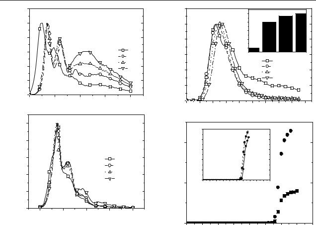
During operation, PLEDs are often heated by the thermal energy released from various nonradiative decay processes, and the heat increases the formation of keto-type defects in emitting polymers such as PFs [10]. To examine the susceptibility to the formation of keto-type defects in elevated temperatures, the pristine PDOF and nanocomposites films spin cast onto quartz plates were placed in a vacuum oven and heated to a series of different temperatures for 8 h. After the films had cooled to room temperature, the PL spectra were recorded. Figure 4 shows the normalized PL spectra of the annealed pure PDOF film and of the PDOF1/MCM1.0 film. In the PDOF film, annealing causes a red shift in the luminescence spectrum. The bandgap of the annealed PDOF film is narrower than that of the unannealed film, due mainly to the change in the ring torsion angle toward coplanarization. After annealing, the spectrum is red-shifted and the low-energy emission peak that is present around 500 nm in the unannealed sample becomes more intense. This increase in the intensity of the secondary peak results from the increased formation of keto defects that occurs as the annealing temperature increases.
1795
J H Park et al
(a) |
1.2 |
|
|
|
|
|
1.0 |
|
|
|
|
(a.u.) |
0.8 |
|
|
|
|
|
|
|
|
|
|
intensity |
0.6 |
|
|
|
25oC |
|
|
|
|
90oC |
|
0.4 |
|
|
|
130oC |
|
L |
|
|
|
160oC |
|
P |
|
|
|
|
|
|
0.2 |
|
|
|
|
|
0.0 |
|
|
|
|
|
400 |
450 |
500 |
550 |
600 |
|
|
Wavelength (nm) |
|
(b) |
|
|
|
|
1.0 |
|
|
(a.u.) |
0.8 |
|
|
0.4 |
130oC |
||
intensity |
|||
|
0.6 |
o |
|
|
|
25 C |
|
|
|
90oC |
|
L |
|
160oC |
|
P |
0.2 |
|
|
|
|
0.0 |
|
|
|
|
400 |
450 |
500 |
550 |
600 |
Wavelength (nm)
Figure 4. (a) Normalized PL spectra of PDOF film thermally annealed for 8 h at different temperatures in air. (b) Normalized PL spectra of PDOF1/MCM2.0 nanocomposite film thermally annealed for 8 h at different temperatures in air.
However, for the PDOF1/MCM2.0 sample, the growth of the secondary emission peak was retarded compared to that of the pure PDOF film. Because of the gas barrier effect produced by the MCM-41 walls, the polymer chain degradation may be dramatically reduced, resulting in high thermal stability.
It should be noted that the previously reported polymer/nanoporous silica nanocomposite systems with submicron particle size could not be applied to PLEDs because the typical emitting layer thickness of PLEDs is about 100 nm. On the other hand, the size of the MCM41 particles used in this work is less than 100 nm, making this nanocomposite system ideal for direct use in PLEDs. To compare the emitting characteristics of the two different emitting layers, namely the pure PDOF and the PDOF/MCM41 nanocomposites, the normalized EL spectra of the devices with the ITO/PEDOT/emitting layer/LiF/Al (ITO: indium tin oxide; PEDOT: poly(3,4-ethylene dioxythiophene)) configuration were measured at a constant current density of 0.2 mA mm−2. Figure 5(a) shows the EL spectra of these devices. The EL spectra of the PDOF/MCM-41 nanocomposite films are obviously narrower than those of the neat PDOF film, and the long-wavelength tail is significantly reduced.
Figure 5(b) shows the device performances with the neat PDOF and PDOF/MCM-41 nanocomposite film
(a) |
1.2 |
(a.u.) |
|
|
|
|
8 |
|
|
(a.u.)intensity |
1.0 |
IntensityAbsoluteEL |
1.6 |
|
|
|
|
|
|
|
|
|
1.4 |
|
|
0.8 |
|
1.2 |
|
|
|
|
1.0 |
|
|
0.6 |
|
PDOF |
PDOF1/MCM0.5 PDOF1/MCM1.0 PDOF1/MCM0.6 |
|
|
|
|
PDOF |
EL |
0.4 |
|
|
PDOF1/MCM0.5 |
|
|
PDOF1/MCM1.0 |
||
|
|
|
|
PDOF1/MCM2.0 |
0.2
0.0 |
|
|
|
|
|
|
|
|
|
380 |
400 |
420 |
440 |
460 |
480 |
500 |
520 |
540 |
560 |
Wavelength (nm)
(b) |
|
|
|
|
|
|
|
|
|
|
|
|
|
|
|
) |
100 |
|
|
|
|
|
|
|
|
|
|
|
|
|
2 |
|
|
|
|
|
|
|
|
|
|
|
|
|
400 |
(mA/cm |
80 |
|
|
|
|
|
|
|
|
|
|
|
|
|
|
|
|
|
|
|
|
|
|
|
|
|
|
|
W/cm(output |
densityCurrent |
60 |
|
|
|
|
|
|
|
|
|
|
|
|
) |
|
|
|
|
|
|
|
|
|
|
|
|
|
|
2 |
|
|
|
|
|
|
|
|
|
|
|
|
|
|
|
|
40 |
|
|
|
|
|
|
|
|
|
|
|
|
|
|
20 |
|
|
|
|
|
|
|
|
|
|
|
|
200 |
|
0 |
|
|
|
|
|
|
|
|
|
|
|
|
|
0 |
1 |
2 |
3 |
4 |
5 |
6 |
7 |
8 |
9 |
10 |
|
|
|
|
|
|
|
|
|
Bias (V) |
|
|
|
|
|
|
|
|
Optical |
|
|
|
|
|
|
|
|
|
|
|
|
|
|
0 |
|
|
|
|
|
|
|
|
|
|
|
|
|
|
0 |
|
1 |
|
2 |
|
|
3 |
|
4 |
|
5 |
6 |
7 |
8 |
Voltage (V)
Figure 5. (a) Electroluminescence spectra for devices (ITO/PEDOT/emitting layer/LiF/Al) that incorporate a PDOF film and PDOF/MCM-41 nanocomposite films as the emitting layer. The inset shows the absolute EL intensity. (b) Light–voltage (L–V ) and current–voltage (I –V ) characteristics of EL devices that incorporate a PDOF film (  ) and PDOF1/MCM2.0 nanocomposite film (•) as the emitting layer.
(PDOF1/MCM2.0) as the emitting layers. After the injected electrons and holes recombine on a single chain in the pore of MCM-41, the newly formed excitons which can move between chains during their life time have lower probability of quenching at defect sites. In addition, when the excitons are created outside the composites the Forster¨ energy transfer from the outside to low-energy sites within the composites may occur. By these effects, we have greatly increased the light output of PDOF-based devices. The emitting light brightness is up to three times higher in a device that uses PDOF/MCM-41 nanocomposite material for the emitting layers than in a device that uses neat PDOF. The maximum quantum efficiency of the nanocomposite LED was 0.3% (ph/el).
4. Conclusions
Blue-light-emitting polymer/nanoporous silica nanocomposite material shows high photostability due to the efficiency of the composite as an oxygen barrier. The PL of the nanocomposite film decays more slowly with time than that of a pure PDOF
1796