

reading / British practice / Vol D - 1990 (ocr) ELECTRICAL SYSTEM & EQUIPMENT
.pdfGenerator voltage switchgear
basically of the butt type in which the moving element presents a hemispherical face to the hollow conical surface of the fixed contact. When opening, the axial air blast flows over the surface of the moving contact and through a circular orifice in the centre of the fixed
contact, see Fig 5.9.
FIXED |
MOVING |
|
CONTACT |
||
CONTACT |
||
|
INTERRUPTER |
INTERRUPTER |
CLOSED |
OPEN |
FIG. 5.9 |
Diagrammatic arrangement of a |
|
main interrupter |
The contact system of the series disconnector comprises a telescopic arrangement in which a cylindrical drum contact moves axially to bridge two sets of fixed clusters of finger type contacts arranged in a circular formation, see Fig 5.10.
MOVING
CONTACT DRUM
DiSCONNECTOR |
oiscoNNec-roR |
CLOSED |
OPEN |
FIG. 5.10 Diagrammatic arrangement of a series disconnector
The switchgear is operated by compressed air, the cin:uit interrupters utilising the air-blast principle. The poles of each three-phase unit are connected pneumatically to operate simultaneously; there is no mechanical interconnection across the poles. Each pole is provided with a discrete unit air receiver, charged at the switchgear operating pressure from a higher pressure ,, toraee system. The capacity of each unit air receiver is sufficient for one close/open cycle of operation
ithout replenishment from the high pressure store. Whilst the interrupter system of the switchgear at
Dinorwig features one 'break' per pole for the electrical performance required, that for Hartlepool and Heysham / necessitated, at the time of placing the order, a double-break arrangement. However, development since has produced a single-break concept of corn-
parable capability. Accordingly, the design accepted for Heysham 2 uses this arrangement.
3.2.2 Control
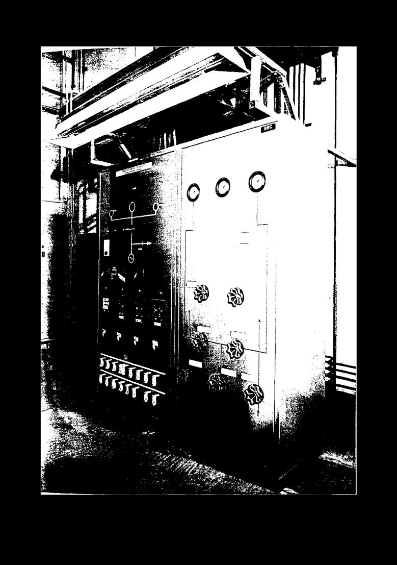
Control of the switchgear is electropneumatie, operation is initiated by electrical activation of the pneumatic system. Each three-pole switchgear assembly is provided with a 'local' control panel of the free-standing cubicle pattern equipped with facilities for both local (at the panel) and remote control — selection of the method of control being made at the panel. Because of the noise of operation, personnel must wear ear protection near the panel when the switchgear is operational. This is an important consideration in the siting of the control panels. Examples of generator circuit-breakers are shown in Figs 5.11, 5.12 and 5.13. Figure 5.14 illustrates a circuit-breaker control panel.
3.2.3 Cooling
The load current carrying duty of the switchgear necessitates forced cooling. The rating involved at Hartlepool and Heysham / and 2 requires a water system, whereas a forced-air scheme suffices for the much lower load current capability involved at Dinorwig. In the former arrangement, de-ionised water is circulated in a closed circuit through the switchgear phase conductors via a raw-water cooled heat exchanger. In the forced-air concept, the air in each pole enclosure is circulated by fan through an air cooled heat exchanger in such a manner as to leave that in the generator main connection trunkings largely uninvolved. Whereas in forced-air cooled installations each pole is dealt with individually — the equipment is an integral part of the enclosure structure — the plant for water cooled switchgear is provided on the basis of one discrete unit per three-phase assembly. Pump capacity in the latter is provided on the basis of two 100% units per plant. Typical arrangements of water cooling plant are shown in Figs 5.15 and 5.16.
3.2.4 Operating air plant
The switchgear operating air plant is reserved wholly for that duty; it supplies no other station services. The capacity/rating of the high pressure storage/ compressor plant is determined by the number of operations of the switchgear to be 'stored', the length of time allowable for the restoration of the HP system to service pressure after a given discharge duty and the requirement that a compressor shall, at each start, run for a period sufficient to attain an acceptable working temperature.
The Hartlepool and Heysham / projects are the first modern CEGB stations to feature the switching of main generators at generator terminal voltage. In these essentially base-load stations, the switchgear is called upon to switch relatively infrequently in normal
343

Switchgear and controlgear |
Chapter 5 |
|
|
FIG. 5.11 Two poles (of a three -phase group) of a forced-air cooled generator circuit-breaker installed at Dinor‘sig pumped-storage power station (British Brown-Boveri Ltd)
(see also colour photograph between pp 496 and 497)
service. The high pressure storage/compressor plant is, therefore, rated primarily to satisfy the needs of s witchgear commissioning initially, and of re-commis- sioning after overhauls. The present practice in baseload installations (Heysham 2 is a current example) is provision of air plant on the basis of:
(a)A dual-pressure system in which air is stored in duplicate groups of high pressure receivers, from which it is fed at lower pressure to the switchgear local (unit) receivers.
(In) One compressor plant per group of HP receivers, connected and controlled so that:
•Each compressor can supply either or both groups of HP receivers.
•Either compressor may be selected to 'run' or 'standby' when connected to supply both groups of HP receivers.
•Both compressors can be run in parallel to supply either or both groups of receivers.
(c High pressure storage of the order of 5-close/ open cycles of operation of one 3-pole switchgear equipment without assistance from the compressor plant.
(d)Compressor capacity, i.e, both compressors running in parallel, capable of restoration to service pressure of the HP system after charging of the air receivers of one 3-pole switchgear equipment
from atmospheric to operating pressure in a period of the order of 3 hours. Such compressor capacity is also capable of replacing the air drawn from the HP storage in 11/4 to 2 h running time in a 5-close/open switchgear operating duty.
It should be explained that the ratio of 'high' pressure storage to 'operating' pressure is sufficient to ensure that expansion from one to the other results in the supply of acceptably dry air to the switcheear. The high pressure storage, and switchgear operating pressures are:
Hartlepool |
High pressure storage |
60 bar nominal |
and Heysham /: |
Swiichgear operating pressure 30 bar nominal |
|
Dinorwig and |
High pressure storage |
1 50 bar nominal |
Heysham 2; |
Switchgear operating pressure |
30 bar nominal |
The normal operating regime at Dinorwie pumpedstorage power station entails a much heavier consumption of switchgear operating air than at Hartlepool and Heysham. These demands are supplied from three
344

Generator voltage switchgear
FR, 5.12 One pole of a forced-air cooled generator circuit-breaker, with side covers and the connection to venerator busbar removed (British Brown-Boveri Ltd)
(see also colour photograph between pp 496 and 497)
,eparate (though interconnectable) dual-pressure com- r[cN,or 'storage plants, i.e, one plant per two generator/
ror machines, each plant comprising high pressure ,:or..gc feeding a lower pressure switchgear operating
The principle of storage at 'high pressure' and
,Ail,:hgcar operation at a lower value, is basically as
Ilarlepool and Heysham / and 2.
I L: Mr stora12.: capacity provided for Dinorwig pcimits v.,. itching of the circuit-breakers, as
|
|
to achieve the following station operating |
|
|
|
unassisted by replenishment from the corn- |
|
|
|
r plant, commencing with the switchgear for |
|
|
|
genermor-motor open, i.e., all six three-phase |
|
,.::-,Aiii-h.reakers open: |
|||
• |
lick-to-hack starting of one machine in the pump- |
||
|
Sic |
by another in the generating mode, cul- |
|
|
|
||
|
|
in a 'five machines pumping' condition. |
|
• |
hangeocer to |
generation of the five machines |
|
|
ilumpin2., i.e., all machines now operating in the |
||
|
,zener,ning mode. |
||
• |
,;t opping all six |
machines. |
|
It was assumed that operational demand could call for the above sequence in a period as short as 45 minutes. It is, therefore, considered representative of the heaviest likely consumption of air during a length of time insufficient for make-up from the compressor plant to be of useful significance.
The distribution of air to the switchgear receivers in the Hartlepool, Heysham 1 and Dinorwig installations is by ringmain. However, the design of the switchgear for the performance required for Heysham 2 demands air for the closing operation at a pressure marginally above that necessary for opening. Advantage is taken of the lower value required for opening to lessen the pressure on seals when the switchgear stands closed, that being the predominant service condition. This is achieved by automatic regulation of the pressure of the air supply to the switchgear receivers to suit the operating mode. It is, of course, essential that the circuit-breakers be capable of operating independently, i.e., allowance must be made for one standing closed — available for opening — whilst the other remains open — available for closure. Thus the operating air pressure requirement of one breaker
345

Jeabiolluop pue Jea6yol!ms
Irir. 5.13 Flu- cc-phase water cooled genermor circuit-breaker sho ,wing conneerion into the generator phase-isolated bushar sysiem ( British Brown -Boyer' Ltd)
(see also colour pholograplt li d weer' pp 496 :mil 497)
Generator voltage switchgear
FIG. 5.14 Generator circuit-breaker control panel (British Brown-Boveri Ltd) (see also colour photograph between pp 496 and 497)
347

Switchgear and controlgear |
Chapter 5 |
|
|
Fic. 5.15 Cooling water plant (British Brown-Boveri Ltd) (see also colour photograph between pp 496 and 497)
348

Generator voltage switchgear
CIRCUIT BREAKER POLES
I |
|
|
I |
I |
0-0441411 |
) |
I |
I |
|
|
I |
L |
RED PRASE |
||
|
..-J |
||
|
|
r- |
|
|
|
|
|
|
|
|
|
-1EADER |
|
|
|
|
|
|
o |
|
n |
||
|
|
|
|||
|
|
|
|
|
|
YELLOW PHASE
o c(4%Iro—c—o 0
BLUE PHASE I-VW-1-*
-J
A
V
DEIONISING
FILTER
HEAT
EXCHANGER
P U MPS
REGULATING VALVE
SERVICE
COOLING
WAT ER
HEAT EXCHANGER'
PUMP ASSEMBLY
FIG. 5.16 Cooling water plant schematic
at any given time, differ from that of the other. A simple ringmain system of supply cannot satisfy such conditions. Each unit is therefore, supplied separately.
Figure 5,17 illustrates a typical operating air sys- IC:111, Fif! 5.18 an air plant control panel, Fig 5.19 a Lompressor set, and Fig 5.20 a battery of high pressure (150 bar) air storage receivers.
3.2.5 Phase-reversal disconnectors for pumpedstorage schemes
In the special case of Dinorwig pumped-storage power station, in addition to the use of generator circuithreakcrs, disconnectors (isolators) are necessary for phase - reversal and machine starting purposes. As with generator circuit-breakers, the clisconnectors are of indoor type construction, designed for connection directly into the phase-isolated system of generator main Li nd starting busbars. Each pole of each group is driven separately by an electric motor in normal service, but v,ith provision for manual operation — the latter
being intended primarily for use during maintenance. Mechanical and electrical interlocking prevents the si multaneous engagement of electrical and manual drives. Electrical operation may be from the 'local' control panel, or from a remote station, e.g., a control room — selection of the mode required being made at the local panel. The facility for remote operation is, of course, essential where the operational requirement necessitates a scheme of automatic control. An 'open- to-close' operation, and vice-versa, electrically, takes approximately 5 s. The drive mechanism housing of each pole carries mechanical flag indication of the operated condition of each pole, i.e., 'open' or 'closed'.
In essence, the mechanical construction of the contact system follows closely that of the series disconnector employed in the generator circuit-breakers at Dinorwig, except that natural, rather than forced, air cooling suffices.
In addition, each pole features a glazed window on either side through which the position of the telescopic contact system can be observed. Figure 5.21 depicts
349

PRESSURE
MAINTAINING
VALVE
COMPRESSORS
_
COMPRESSOR |
|
|
||
I |
ZE |
I |
|
|
C(2 |
T L |
|
PRESSURE REDUCTION PANEL |
|
_ |
|
r |
01 |
|
|
|
|
|
|
1
1
P1 - COMPRESSOR 1
P2- COMPRESSOR 2
P3-ALARM
Foci. 5.17 Typical operaiiiig air . .,;ysiciii
DRAIN VALVE
LOCAL TO
GENERATOR
- - - SWITCHGEAR II
k
L _ _ _ _J
GENERATOR SWITCHGEAR CONTROL PANEL
GENERATOR t
GENERATOR
SWITCHGEAR
LOCAL AIR
RECEIVERS
GENERATOR 2
rWl
Jea6lailuoo pue Jea6qo

Generator voltage switchgear
FR., 5.18 Air plant control panel (British Brown-Boveri Ltd) (see also colour photograph between pp 496 and 497)
\ingle-pole eNample of a disconnector with the top hdlt- of the enclosure removed.
.1 he disconnectors, although off-load 'switching' de- \ Lce ,, by definition, have a capacitive current breaking , LIPability. For the purpose of uniformity of design and on , truction, all disconnectors, wherever positioned in [he 18 kV system, have an insulation level, normal cur- rent carr ■.i ng, and short-circuit current withstand capahilny matching that of the generator circuit-breakers.
3.2.6Earthing switches
•\ recent introduction into CEGB practice is the use
of earthing switches for the earthing, during maintenance, of generators and their main connections. These switches comprise single-pole units designed specifically for incorporation into phase-isolated systems in such manner as to preserve the principle of 'phaseisolation'. Each pole of a three-phase group is driven individually by an electric motor, provision being made for operation local to the switch, or from a remote station. It can also be operated manually, primarily during maintenance of the switch, but only when the electrical drive is disconnected. Each pole carries a mechanical flag indication of the contact system position, i.e., 'open' or 'closed'.
351

Switchgear and controlgear |
Chapter 5 |
|
|
Fin. 5.19 Typical air compressor set (British Brown-BoYeri Ltd)
The insulation level and short-circuit current withstand capabilities of the switches are, of course, matched to the requirements of the system of generator main connections. As throughout the power station, the earthing of main circuit (i.e., power circuit) conductors is attended by stringent rules governing isolation and making 'dead', supported, wherever possible and practicable, by electrical and mechanical interlocking — the latter often featuring the use of coded keys. The earthing switches described here are so interlocked. Each pole being operable independently allows closure to earth sequentially. Thus, in the event of inadvertent activation of a switch to dose — an act likely only in consequence of gross breach of CEGB Safety Rules — the closure of that phase alone would initiate the system earth fault protection; the fault current flow in such an event being limited by the neutral earthing resistor to a value within the 'making' capability of the switch. Figure 5.22 shows a single-pole switch dismounted, and Fig 5.23 a three-phase group connected into a phase-isolated system of busbars.
Essentially, the switches comprise a fixed and moving_ contact assembly housed in a cylindrical enclosure of insulation material, mounted in each phase of the phase-isolated busbar system. The fixed contact is se-
cured to the busbar, the moving contact being driven down into engagement with it in a vertical plane. Heavy conductors connect the mounting flange of each switch of a three-phase group to provide a three-phase shortcircuit connected to the power station main earthing system.
4 3.3 kV and 11 kV switchgear — circuitbreaker equipment
4.1 Required performance
The design parameters to meet system requirements for this switchgear are described in the following subsections.
4.1.1 Rated voltage
The rated voltage is the value of voltage used to designate the switchgear and to which is related its operating performance. The rated voltage indicates the upper limit of the highest voltage of systems for which the switchgear is intended. For polyphase systems it is stated as the RMS value of the voltage between phases.
352