

reading / British practice / Vol D - 1990 (ocr) ELECTRICAL SYSTEM & EQUIPMENT
.pdfGeneral design and construction
:a)
EL
QJ
BLUE YELLOW RED
IC'
FIG. 3.49 Connections of single-phase generator transformer bank
110., SWITCHGEAR
[.
[ CORI,11 TOR O L c, M
I--.
AV SWITCHGEAR
UNIT
TURBINE
HALL
UNIT 2
II 33k/ TRANSFORMERS
A
331.4 i,41ET)
SWiTC ,-EGEAR BOOM
PRECIPiTATORS
BOILER
HOUSE
|
|
|
|
l•l |
|
IMI |
1133kV8.31 a-MEW |
|
|
|
TRANSFORMERS |
FIG. 3.50 Location of 11/3.3 kV and 3.3/0.415 kV transformers in a coal-fired station
II |
|
|
|
|
|
|
ir |
|
|
8:::::::s |
|
III |
|
|
acm:si |
||
|
|
TURBINE |
|
|
|
|
|
HALL |
|
|
|
FIG. 3.51 Two-unit nuclear station: 11/3.3 kV and 3.3/0.415 kV transformers located between reactor and turbine buildings
•The need for adequate drainage.
•The provision of necessary oil interception.
As with the main transformers it is possible to make economies, particularly in respect of the last three factors, by the grouping of auxiliary transformers together. Any grouping, however, must have in mind the need to segregate alternative sources of supply to main switchboards, so that any single incident would not make both of them unavailable.
For smaller auxiliary transformers, providing supplies at 415 V, the fire hazard can be removed by eli minating oil: this can be achieved by the use of low flammability or fire-resistant fluid, or by the elimination of fluid altogether and making them air cooled. Whatever the method employed, and the merits of
the alternative systems available are discussed in Section 2.4 of this chapter, the purpose is to enable the transformers to be located indoors within switchrooms. These can thereby be placed very near to, or even integral with, LV switchgear, thus eliminating LV cabling. The benefits from this are considerable and are discussed further in Section 2.4.
1.7 Quality assurance and testing
t7.1 Quality assurance (QA)
Unlike many items of power station electrical plant (for example, switchgear and motors) most transformers are virtually handmade, little or no mass production is employed in manufacture and each is produced very
243
Transformers |
Chapter 3 |
|
|
much as a one-off. This means that the user cannot rely on extensive type testing of pre-production prototypes to satisfy himself that the design and manufacture renders the transformer fit for service, but must have such proving as is considered necessary carried out on the transformer itself. From a series of works tests, which might at most be spread over a few days, it is necessary to ascertain that the transformer will be suitable for thirty years or more in service. It is therefore logical that this testing should be complemented by a system of QA procedures which operate on each individual unit and throughout the whole design and manufacturing process.
Details of operation of QA systems are beyond the scope of this volume and anyway these are covered adequately elsewhere, for example, by BS5750 [8], but it must be pointed out that testing alone will not demonstrate that the transformer is fully compliant with all the requirements which must be placed upon it.
1.7.2 Tests during manufacture
As part of the manufacturer's QA system, and also to meet the requirements of the specification, some testing will of necessity be carried out during manufacture and it will be appropriate to consider the most important of these in some detail. These are:
Incoming core plate is checked for thickness and quality of insulation covering. A sample of the material is cut and built up into a small loop (Epstein Square) on which a measurement of specific loss can be made.
This is checked by megger and by application of a 2 kV RMS or 3 kV DC test voltage on completion of erection of the core, and again following replacement of top yoke after fitting the windings.
Core-loss measurement If there are any novel features associated with the core design or if the manufacturer has any other reason to doubt whether the guaranteed core loss will be achieved, then this can be measured by the application of temporary turns to allow the core to be excited at normal flux density before the windings are fitted.
If continuously-transposed conductor (see Section 1.4.6 of this chapter) is to be used for any of the windings, strand-to-strand checks of the enamel insulation are carried out directly the conductor is received in the works.
The first tank of any new design is checked for stiffness and vacuum-withstand capability. For 275 and 400 kV transformers, a vacuum equivalent to
to 25 mbar absolute pressure is applied. This need only be held long enough to take the necessary readings and verify that the vacuum is indeed being held, which might take up to 2 hours for a large tank. After release of the vacuum, the permanent deflection of the tank sides is measured and must not exceed specified limits of up to 13 mm, depending on length. Following this test, a further test is carried out at a pressure equivalent to 3 mbar absolute for 8 hours for the purpose of checking mechanical-withstand capability.
Wherever practicable, tanks are checked for leaktightness by filling with a fluid of lower viscosity than transformer oil, usually white spirit, and applying a pressure of 700 mbar, or the normal pressure plus 350 mbar, whichever is the greater, for 24 hours. All welds are painted for this test with a flat white paint which aids detection of any leaks.
1.7.3 Processing and dry-out
The build-up towards the final works testing of a large power station transformer commences some time before it actually enters the test bay, at the stage at which the final processing and dry-out begins.
Paper insulation and pressboard material, which make up a significant proportion by volume of the transformer findings, absorb large amounts of moisture from the atmosphere. The presence of this moisture brings about a reduction in dielectric strength and also an increase in volume. This increase in volume is such that, until the windings have been given an initial dry-out, it is impossible to reduce their length sufficiently to fit them on to the leg of the core and to fit the top yoke in place.
The final drying-out is commenced either when the core and windings are placed in an autoclave or when they are fitted into their tank, all main connections made, and the tank placed in an oven and connected to the drying system. The tapping switch may be fitted at this stage, or later, depending on the ability of the tap switch components to withstand the drying process.
Traditional methods of drying-out involve heating the windings and insulation to between 85 ° and 120 ° C, circulating dry air and finally applying a vacuum to complete the removal of water vapour and air from the interstices of the paper before admitting oil to cover the windings. For a small transformer operating at up to, say, 11 kV, this heating could be carried out by placing the complete unit in a steam or gas-heated oven. For a large transformer this process would take several days, or even weeks, so that nowadays the preference is to use a vapour-phase heating system in which a liquid, such as white spirit, is heated and admitted to the transformer tank under low pressure as vapour. This condenses on the core and windings, and as it does so, releases its latent heat of vaporisation, thus causing the tank internals to be rapidly heated. It is necessary to ensure that the insulation does not exceed a • temperature of about 130 ° C to prevent ageing damage:
244
General design and construction
when this temperature is reached, the white spirit and water vapour is pumped off. Finally, a vacuum equivalent of between 0.2 and 0.5 mbar absolute pressure is applied to the tank to complete removal of all air and vapours. During this phase, it is necessary to supply further heat to provide the latent heat of vaporisation; this is usually done by heating coils in an autoclave, or by circulating hot air around the tank
v,ithin the dry-out oven.
The vapouphase dry-out process is similar to systems used previously, the only difference being in the use of the vapour to reduce the heating time. it is not a certain method of achieving a drier transformer and, in fact, it is possible that the drying of large masses of insulation might be less efficient since, being limited by the rate of diffusion of water through the material, it is a process which cannot be speeded up. This is an area where further research might be beneficial. The other aspect of this system of dryingout which requires special attention is that of the compatibility of the transformer components with the heat transfer medium. For example, prior to the use of the vapour phase process, some nylon materials were used for transformer internals, notably in a type of self-locking nut. This nylon is attacked by hot white spirit, so it was necessary to find an alternative.
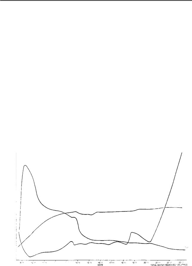
Monitoring insulation dryness during processing usually involves measurement of some parameter which
is directly dependent on moisture content. Insulation resistance or power factor would meet this requirement. Since there are no absolute values of these which can be applied to all transformers, it is usual to plot readings graphically and dry-out is taken to be completed when a levelling out of power factor and a sharp rise in insulation resistance is observed. Figure 3.52 shows typical insulation resistance and power factor curves obtained during a dry-out. Vacuum is applied when the initial reduction in the rate-of-change of these parameters is noted: the ability to achieve and maintain the required vacuum, coupled with a reduction and levelling-out of the quantity of water removed and supported by the indication given by monitoring of the above parameters, will confirm that the required dryness is being reached. For a vapour phase drying system, since it could be dangerous to monitor electrical parameters, drying termination is identified by monitoring water condensate in the vacuum pumping system. At this point oil filling is begun with dry, filtered, degassed oil at a temperature of about 75 ° C being slowly admitted to the tank and at such a rate as to allow the vacuum already applied to be maintained.
Drying-out of insulation is accompanied by significant shrinkage, so it is usual practice for a large transformer to be de-tanked immediately following initial oil impregnation to allow for retightening of all windings, as well as cleats and clamps on all leads and
|
|
|
|
1 311 |
1 |
9 |
|
C ' ' |
121' |
16 11 |
|
|
|
|
|
|
DATE |
Flo. 3.52 Insulation resistance and power factor curves during dry-out
245
Transformers |
Chapter 3 |
|
|
insulation materials. This operation is carried out as quickly as possible in order to reduce the time for which windings are exposed to the atmosphere. However, once they have been impregnated with oil, their tendency to absorb moisture is considerably reduced so that, provided the transformer is not out of its tank for more than about twenty-four hours, it is not necessary to repeat the dry-out process. On returning the core and windings to the tank, the manufacturer will probably have a rule which says that vacuum should be applied for a time equal to that for which they were uncovered, before refilling with hot, filtered, degassed oil.
Before commencement of final works tests, the transformer is then usually left to stand for several days to allow the oil to permeate the insulation fully and any remaining air bubbles to become absorbed by the oil.
1.7.4 Final testing
Standard CEGB transformer test requirements are set out in BEBS T2 (1966). For the convenience of the reader the information is repeated in Tables 3.1 and 3.2.
Final works tests for a transformer fall into three categories:
•Tests to prove that the transformer has been built correctly These include ratio, polarity, resistance, and tapchange operation.
• Tests to prove guarantees These are losses, impedance, temperature rise, noise level.
• Tests to prove that the transformer will be satisfactory in service for at least thirty years The tests in this category are the most important and the most difficult to frame: they include all the dielectric or overvoltage tests, and load current runs.
Full details of all tests in the first two categories above can be found in BS171 and are described at length in most standard textbooks. What is more, the tests themselves are logical and the outcome is beyond discussion. This section is concerned only with those tests included in the third category and aims to examine how the customer can best be satisfied that the transformer which he is buying has a reasonable chance of meeting the demands placed upon it for a lifetime in service.
TABLE 3.1
Summary of final works testing for generator, station and unit transformers
(a) Tests to prove correct manufacture |
|
Test defined in |
Routine test (R) |
|
|
|
Type test (T) |
|
|
|
|
Winding resistances |
|
BS 171 1970 Clause 36 |
|
Phasor group |
|
BS 171 1970 Clause 37 |
|
Voltage ratio |
|
BS 171 1970 Clause 37 |
|
Polarity |
|
BS 171 1970 Clause 37 |
|
Tapchange operation* |
|
|
|
Insulation resistances |
|
|
|
* Generator and station |
|
|
|
transformers only |
|
|
|
(b) Tests to prove guarantees |
|
|
|
No load loss |
|
BS 171 1970 Clause 40 |
|
Magnetising current |
|
BS 171 1970 Clause 40 |
|
Load loss |
|
BS 171 1970 Clause 39 |
|
I mpedances |
|
BS 171 1970 Clause 38 |
|
Zero sequence impedance |
|
BS 171 1970 Clause 48 |
|
Transformer noise level |
|
I EC 551 |
|
Cooler noise level |
|
I EC 551 |
|
Temperature rise |
|
BS 171 1970 Clause 41 |
|
(c) Tests to prove 'quality' |
|
|
|
Load current run * |
|
13EBS T2 Section 1 |
|
Induced overvoltage including |
|
BS 171 1970 Clause 43 |
|
partial discharge measurement |
|
and BEBS T2 |
|
Applied voltage |
|
BS 171 1970 Clause 44 |
|
Additional voltage* |
|
BEBS T2 Section I |
|
Switching surge voltage* |
|
BS 171 1970 Clause 46 |
|
I mpulse voltage including |
|
|
|
chopped waves |
|
|
|
|
|
|
|
246

General design and construction
TABLE 3.2
Summary of final works testing for auxiliary transformers
(a) Tests to prove correct manufacture |
Test defined in |
Routine test (R) |
|
|
Type test (T) |
|
|
|
Winding resistances |
13S 171 1970 Clause 36 |
|
Phasor group |
BS 171 1970 Clause 37 |
|
Voltage ratio |
BS 171 1970 Clause 37 |
|
Polarity |
BS 171 1970 Clause 37 |
|
Tapchange operation (if fitted) |
|
|
insulation resistances |
|
|
(b) Tests to prove guarantees |
|
|
No-load loss |
BS 171 1970 Clause 40 |
|
Magnetising current |
BS 171 1970 Clause 40 |
|
Load loss |
BS 171 1970 Clause 39 |
|
I mpedances |
BS 171 1970 Clause 38 |
|
Transformer noise level |
I EC 551 |
|
Temperature rise |
BS 171 1970 Clause 41 |
|
415 V busbar tests# |
|
|
(c) Tests to prove 'quality' |
|
|
Induced overvoltaee including |
BS 171 1970 Clause 43 |
|
partial discharge measurements |
|
|
Applied voltage |
BS 171 1970 Clause 44 |
|
I mpulse voltage including |
BS 171 1970 Clause 46 |
T* |
chopped waves |
|
|
|
|
|
# AN transformers only |
*Routine on A N transformers |
|
|
|
|
To do this, it is reasonable to start by considering how the transformer is likely to fail. There are, of course, many failure mechanisms for something as complex as a large transformer, but it is likely that these will fall into one of three classes:
•Insulation will break down under the influence of the applied voltage stress.
•Insulation will be prematurely aged, due to overheating.
•Windings will suffer mechanical failure, due to inability to withstand the applied forces.
Since failure mechanisms are complex, any particular failure might even be difficult to classify, being possibly due to a combination of more than one of the above causes. Overheating, for example, especially if not too severe, often will not itself cause failure, but will reduce the mechanical strength of the insulation, so that when the transformer is subjected to some mechanical shock, such as a system fault close to its terminals, it v, ill then fail. It is possible, too, that inadequate mechanical strength which allows movement of conductors could cause the reduction of electrical clearances so that it is electrical breakdown which causes failure.
Even though failure modes are not always straightforward, the suggested classification allows objective discussion of appropriate methods of testing.
1.7.5 Power frequency oyeryoltage tests
The traditional approach towards demonstrating that insulation will not be broken down by the applied voltage has been to apply a test voltage which is very much greater than that likely to be seen in service. This is the philosophy behind the overpotential test, which involves the application of twice normal voltage. Traditionally this was applied for one minute, but BS171 (1978) now allows this to be for a period of 120 times the rated frequency divided by the test frequency (in seconds), or 15 s, whichever is the greater. The test frequency is increased to at least twice the nominal frequency for the transformer to avoid overfluxing of the core and is often of the order of 400 Hz, so that test times of fifteen to twenty seconds are the norm. The test is thought by many to be a very crude one akin to striking a test specimen with a very large hammer and observing whether or not it breaks. Considerable effort has therefore been applied in recent times to improving this test and this has largely been brought about by the introduction of partial-discharge measurements during the application of the overvoltage.
Long before the total failure of transformer insulation occurs during overpotential conditions, minute discharge currents will flow. These tend to be triggered at the same point of successive cycles of the applied test frequency voltage waveform and to appear as pulses of high frequency disturbance in the band. Suitable detection equipment can be coupled to the winding
247
Transformers |
Chapter 3 |
|
|
under test, usually via the test tapping of the transformer bushing, and the disturbances can . either be displayed on an oscilloscope or measured directly on a voltmeter designed for radio interference voltage measurement. A measure of the peak value of the discharge can be obtained on the oscilloscope by comparison with the signal obtained by injection of a known pulse into the detector.
Very occasionally, partial-discharge measurements made in this way can give a warning preceding total failure and the test voltage can be removed before complete breakdown, thus avoiding extensive damage. More often, however, the diagnosis is less clear-cut. It could be that measurements taken as the test voltage is being reduced indicate a tendency towards hysteresis, i.e., the discharge values for falling voltage tend to be greater than those obtained as the voltage is being increased. This could indicate that application of the test voltage has caused damage. It is CEGB practice to specify that, as the overvoltage is reduced, the discharge should fall to a nominal level (usually 100 picocoulombs) at an adequate margin above the normal working voltage, say, 1.2 p.u.V.
There is a viewpoint in some international circles that, because of the extra refinement which partialdischarge measurement has brought to overpotential testing, it is no longer necessary to use a test voltage as severe as twice normal volts. This view has led to the method of overpotential testing detailed in IEC 76-3, Clause 11.4, Method 2 [9]. In this test, a voltage of 1.3 or 1.5 p.u.V is applied for 5 minutes. This is then raised to J3 p.u.V for 5 s followed by a return to 1.3 or 1.5 p.u.V which is then held for thirty minutes. Partial-discharge is recorded throughout the test and a close watch made for signs of any tendency for this to increase or run away during the test period. The choice between 1.3 and 1.5 p.u.V for the major proportion of the test time is to be agreed between manufacturer and purchaser. If the figure of 1.3 p.u.V is applied, then the partial-discharge shall not exceed 300 pC; if 1.5 p.u.V is used, then the value should not exceed 500 pC.
Whilst it is clear that some constructive thought has gone into the framing of this test, it is the CEGB view that the degree of overpotential is too modest and it is not proposed to replace the 'twice normal voltage' test in CEGB specifications.
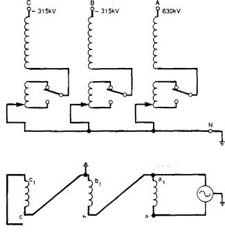
A further point to be noted is that, whilst the induced overvoltage test is usually thought of as a 'twice normal voltage' test, for very high voltage transformers, it can be even more severe than this. Figure 3.53 shows the arrangement for carrying out the induced overvoltage test on a 400 kV transformer having graded insulation on the star-connected HV winding and a delta-connected LV winding. The test supply is taken from a single-phase generator connected to each phase of the LV in turn. The diagram shows the arrangement for testing phase A. In accordance with BS171, 1978, Clause 20 and Table 8, a voltage of 630 kV to earth
|
|
|
|
|
|
|
A |
|
|
- 315kV |
• 630kV |
315kV |
+28.9kV
2 |
|
2 -28.9kV |
|
630 kV TO EARTH INDUCED IN A PHASE UNE TERMINAL 945kV INDUCED BETWEEN A & B PHASE TERMINALS
FIG. 3.53 Arrangement of induced overvoltaee test on a three-phase star/delta 400/23.5 kV generator transformer
must be induced at the line terminal. BS171 does not specify on which tapping the transformer should be connected and so the manufacturer usually opts for position 1 which corresponds to maximum turns in circuit in the [-IV winding. This might be the +6.66% tap for a generator transformer, which could correspond to 460.5 kV for a transformer having an opencircuit voltage of 432 kV on the principal tap. This is the line voltage, so the phase voltage appropriate to position 1 is 460.5/V3 = 265.8 kV: the test voltage of 630 kV induced in this winding therefore represents 2.37 times the normal volts/turn.
It will be seen from Fig 3.53 that during the induced overvoltage test, although all parts of the windings experience a voltage of more than twice that which normally appears between them, that section of the winding which is nearest to earth is not subjected to a very high voltage to earth. This is so even for fullyinsulated windings which, when tested, must have some point tied to earth. It is therefore necessary to carry out a test of the insulation to earth (usually termed 'major insulation' to distinguish this from interturn insulation) and, for a fully-insulated winding, this is usually tested at about twice normal volts. For a winding having graded insulation, the test is at some nominal voltage; for example, for 400, 275 and 132 kV transformers, it is specified as 45 kV in BEBS T2 (1966), Section 1 [10].
In addition to partial-discharge measurement, another diagnostic technique to detect incipient failure
248
|
|
|
|
|
|
|
General design and construction |
||||
|
|
|
|
|
|
|
|
|
|
|
|
|
has made progress in recent years: this is the detection |
|
|
|
|
|
|
|
|
|
|
|
and analysis of dissolved gases in transformer oil. |
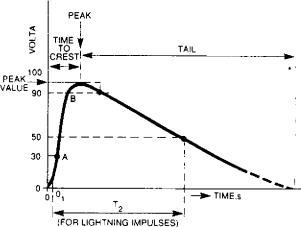
T, DURATION OF WAVEFRONT 1 67 TIMES THE INTERVAL BETWEEN 30% |
|||||||||
|
When partial-discharee or flashover or excessive heat- |
AND 90% OF THE PEAK VALUE |
|
|
|
|
|||||
|
|
|
|
|
|
|
|
|
|
|
|
|
ing takes place in transformer oil, the oil breaks down |
T TIME TO HALF VALUE = THE INTERVAL BETWEEN THE ORIGIN 0 AND 0 1 |
|||||||||
|
into hydrocarbon eases. The actual gases produced |
AND THE 50% PEAK |
|
|
|
|
|||||
|
|
|
|
|
|
|
|
|
|
|
|
|
and their relative ratios are dependent on the tempera- |
|
ei |
|
|
|
|
|
|
|
|
|
ture reached. This forms the basis of the dissolved- |
|
|
|
|
|
|
|
|
|
|
|
g as analysis technique which originally found use as |
|
ui |
|
PEAK |
|
|
|
|
|
|
|
|
(.1 |
|
|
|
|
|
|
|
|
|
|
|
|
|
|
|
|
|
|
|
|
|
|
a tool to assist in the diagnosis of faults in service. |
|
|
|
TIME |
|
|
|
|
|
|
|
When faults occur during works tests, the volumes of |
|
|
|
TO |
|
TAIL |
|
|||
|
|
|
|
ORESTI |
4 |
|
|
|
|
|
|
|
|
|
|
|
|
|
|
|
|||
|
the gases produced are very small and these diffuse |
|
|
|
.41-11.1 |
|
|
|
|
|
|
|
|
|
|
|
|
|
|
• |
|||
|
|
|
|
|
|
|
|
|
|
|
|
|
through very large quantities of oil. Although the |
|
|
|
|
|
|
|
|
|
|
|
starting condition of the oil is known and its purity is |
|
|
|
|
|
|
|
|
|
|
|
very high, very careful sampling and accurate analysis |
|
|
|
|
|
|
|
|
|
|
|
of the oil is necessary to detect these gases. Analysis |
|
|
|
|
|
|
|
|
|
|
|
is assisted if the time for the test can be made as long |
|
|
|
|
|
|
|
|
|
|
|
as possible, and this was the philosophy behind the |
|
|
|
|
|
|
|
|
|
|
|
three-hour overpotential test which was introduced |
|
|
|
|
|
|
|
|
|
|
|
by the CEGB in the early 1970s. It must be emphasised |
|
|
|
|
|
|
|
|
|
|
|
hat this test is carried out in addition to the 'twice |
|
|
|
|
|
|
|
|
|
|
|
normal volts' test. 130% of normal volts is induced for |
|
|
|
|
|
|
|
|
|
|
|
a period of three hours. In order that the magnetic |
|
|
|
FIG. 3.54 Standard |
i mpulse wave |
|||||
circuit, as well as the windings, receives some degree |
|
|
|
|
|
|
|
|
|
|
|
of overstressing, the test frequency is increased only to |
|
|
|
|
|
|
|
|
|
|
|
60 Hz rather than the 65 Hz which would be necessary |
a new design as a means of demonstrating that this |
||||||||||
|
to prevent any overfluxing of the core. Partial-discharge |
has correctly incorporated the necessary features to |
|||||||||
|
levels are monitored throughout the three hours. Oil |
withstand the stresses produced under surge condi- |
|||||||||
|
samples for dissolved-gas analysis are taken before the |
tions. However, in addition, they are now regarded by |
|||||||||
|
test, at the midway stage and at the conclusion. |
the CEGB as a very searching check of quality which |
|||||||||
|
|
can provide further information to assist in proving |
|||||||||
|
1.7.6 Impulse tests |
that each transformer will be suitable for its defined |
|||||||||
|
service lifetime. Impulse tests, including chopped waves, |
||||||||||
|
Mention was made in Section 1.4.10 of this chapter that |
||||||||||
|
are therefore specified for all windings of all power |
||||||||||
a power station transformer in service will, from time |
station transformers having operating voltages of 3.3 |
||||||||||
to time, be subjected to surges caused by lightning or |
kV and above. |
|
|
|
|
||||||
by switching, and that the effect of these on the trans- |
A standard CEGB transformer specification would |
||||||||||
former windings is different from the effects of power |
therefore call for an impulse test consisting of seven |
||||||||||
frequency voltages. The impulse test was devised as a |
shots, as follows: |
|
|
|
|
||||||
si mulation of a lightning strike on the line near to the |
|
|
|
|
|
|
|
|
|
|
|
connection to the transformer and to test the perfor- |
|
|
|
I — Reduced full-wave |
|||||||
mance of the transformer in response to this risk. |
|
|
|
1 — 100% full-wave |
|||||||
|
A standard impulse wave is defined in BSI71 and is |
|
|
|
|||||||
|
|
|
|
2 — 115% chopped-waves |
|||||||
illustrated diagrammatically in Fig 3.54. It has a front |
|
|
|
||||||||
|
|
|
2 — 100% full-waves |
||||||||
ti me of 1.2 As and a time to decay to half-peak of |
|
|
|
||||||||
50 its. A tolerance of +30% is allowed on the front |
|
|
|
|
|
— Reduced full-wave |
|||||
ti me and +20% for the time to half-peak. |
|
|
|
|
|
|
|
|
|
|
|
|
In addition to these standard impulses, chopped- |
It is assumed that the first full-wave shot, at about |
|||||||||
vave tests may be specified which simulate the con- |
75% of the nominal full-wave impulse test level, will |
||||||||||
dition of a flashover of an external co-ordinating gap |
not break down the transformer and so the voltage |
||||||||||
close to th,e terminals of the transformer. For these, |
and current records of that shot are taken as the |
||||||||||
a rod gap or some similar device is placed across the |
reference standard. Assessment as to whether the trans- |
||||||||||
transformer test connection and earth. The size of the |
former has passed or failed is basically made by com- |
||||||||||
gap is such that it flashes over as the impulse wave |
paring the records for the final 75 07w reduced full- |
||||||||||
reaches its peak. This causes a very rapid collapse of |
wave with those for the initial one. Chopping of the |
||||||||||
the voltage applied to the transformer windings, which |
chopped-wave shots is specified to take place between |
||||||||||
results in a very rapid rate-of-change of voltage and |
2 and 6 its from the start of the wave. The amplitude |
||||||||||
high electrical stress in the windings. |
is increased to 115% of the specified full-wave level |
||||||||||
|
I mpulse tests are regarded in BS17I as type tests, |
in order to ensure that the voltage is at least 100% |
|||||||||
i.e., they are carried out on the first transformer of |
of the specified level at the instant of chop. |
||||||||||
249
Transformers |
Chapter 3 |
|
|
I mpulse tests differ from power frequency tests in that, although very large test currents flow, they do so only for a very short time. The power level is therefore quite low and the damage done in the event of a failure is relatively slight.
If a manufacturer suspects that a transformer has a fault, say from the measurement of high partialdischarge during the overpotential test, he may prefer to withdraw the transformer from this test and apply an impulse test which will produce a less damaging breakdown. On the other hand, the very fact that damage tends to be slight can make the location of an impulse test failure exceedingly difficult. Diagnosis of impulse test failures can themselves be difficult, since sometimes only very slight changes in the record traces are produced. For further information on impulse testing and diagnosis techniques the reader is
referred to the Electricity Councils 'Guide on Impulse Voltage Testing Power Transformer and Reactors [111'
or any other standard textbook on the subject.
1.7.7 Switching-surge tests
Surges generated by lightning strikes have very steep rise-times which cause transformer windings to appear as a string of distributed capacitance rather than the inductance which is presented to a power frequency voltage. Surges generated by system switching do not have such rapid rise-times — times of 20 its are typical — and at this frequency the transformer winding behaves much as it would do at 50 Hz. The voltage is evenly distributed, flux is established in the core and voltages are induced in other windings in proportion to the turns ratio. The magnitude of switching surges, though generally lower than lightning surges, is considerably greater than the normal system voltage (perhaps 1.5 times or twice), so that the overpotential test is not an adequate test for this condition. Switching-surge tests are therefore carried out on all transformers which might be subjected to switching surges in service. Three shots are carried out at a level equivalent to 80% of the full-wave impulse test level, with a waveshape having a front time of 20 as and a tail of at least 480 as.
1.7.8 Load runs
The second possible mode of transformer failure listed in Section 1,7.4 of this chapter, is premature ageing of insulation due to overheating. It is therefore important that the opportunity is taken to investigate the thermal performance of the transformer during works testing as fully as possible, in an attempt to try to ensure that no overheating will be present during the normal service operating condition.
Conventional temperature rise tests, for example, in accordance with BS171, are less than ideal in two respects:
•They only measure average temperature rises of oil and windings.
•By reducing the cooling during the heat-up period, manufacturers can shorten the time for the test to as little as eight or ten hours.
Such tests will have little chance of identifying localised hot spots which might be due to a concentration of leakage flux or an area of the winding which has been starved of cooling oil. The CEGB apprOach to searching out such possible problems is to subject the transformer to a run during which it will carry a modest degree of overcurrent for about thirty hours. The test is specified as a period at 110% full-load current, or a current equivalent to full-load losses supplied, whichever is the greater, for twelve hours at each extreme tap position, with each twelve hours commencing from the time at which it reaches normal working temperature. Also, during this load-current run, the opportunity can be taken to monitor tank temperatures, particularly in the vicinity of heavy flanges, cable boxes and bushing pockets, and heavy current bushings. Both extremes of the tapping range are specified since the leakage flux pattern, and therefore the stray loss pattern, is likely to vary with the amount of tapping winding in circuit. Oil samples for dissolved-gas analysis are taken before the test and at the conclusion of each twelve-hour run. If the transformer is the first of a new design, then gradients and top oil and resistance rises are measured in accordance with BS171. However, the main purpose of the test is not to check the guarantees but to uncover evidence of any localised overheating should this exist.
1.7.9 Short-circuit testing
It is in relation to short-circuit performance and the demonstration that a transformer has adequate mechanical strength that the customer is in the weakest position. Section 1.4.12 of this chapter described the nature of the mechanical short-circuit forces and made an estimate of their magnitude. However, for all but the smallest transformers, the performance of practical tests is impossible due to the enormous rating of test plant that would be required. IEC 76-5 [9), deals with the subject of ability to withstand both thermal and mechanical effects of short-circuit. This
it does under the separate headings of |
thermal |
and |
dynamic ability. |
deriving |
the |
For thermal ability, the method of |
RMS value of the symmetrical short-circuit current is defined, as is the time for which this is required to be carried, and the maximum permissible value of average winding temperature permitted after shortcircuit (dependent on the insulation class). The method of calculating this temperature for a given transformer is also defined. Thus this requirement is proved entirely by calculation.
250

General design and construction
For the latter, it is stated that the
to withstand short-circuit can only be demonstrated by testing; however, it is acknowledged that transformers over 40 MVA cannot normally be tested. A procedure for testing transformers below this rating involving the actual application of a short-circuit is described. Oscillographic records of voltage and current are taken for each application of the short-circuit and the assessment of the test results involves an examination of these, as well as an examination of the core and windITPS after removal from the tank. The Buchholz relay, if fitted, is checked for any gas collection. Final assessment on whether the test has been withstood is based on a comparison of impedance measurements taken before and after the tests. It is suggested that a change
of more than 2 0Io in the measured values of impedance are indicative of possible failure.
This leaves a large group of transformers which cannot be tested. Although this is not very satisfactory, service experience with these larger transformers over a considerable period of time has tended to confirm that design calculations of the type described in Section 1.4.12 of this chapter are producing fairly accurate results. Careful examination of service failures of large transformers, especially where there may be a suspicion that short-circuits have occurred close to the transformer terminals, can yield valuable information concerning mechanical strength as well as highlighting specific weaknesses and giving indication where weaknesses may be expected in other similar designs of transformer. On occasions, such an approach has enabled incipient failures to be identified from internal inspections made during a planned outage before these have caused catastrophic failures which would have resulted in extensive damage as well as unscheduled loss of generation.
1.8 Transport, installation and commissioning
1.8.1 Transport
The generator transformer is usually one of the three largest and heaviest single loads to be delivered to a power station site. (The other two being the generator stator and the stator frame.) Transport considerations will therefore have a considerable bearing on the generator transformer design and more will be said on this subject in Section 2.2 of this chapter which deals specifically with generator transformers. For the other large transformers (station and unit transformers), it is usually only necessary to ship these without oil to ensure that they are comfortably within the appropriate transport limits, although it is necessary to check that when mounted on the transport vehicle the height is within the over-bridge clearances which, for trunk roads within the United Kingdom, allows a maximum travelling height of 4.87 m (sixteen feet).
If the tank has been drained for transport, it is necessary for the oil to be replaced by either dry air or nitrogen, which must then be maintained at a slight positive pressure above the outside atmosphere to ensure that the windings remain as dry as possible whilst the oil is absent. This is usually arranged by fitting a high pressure gas cylinder with a reducing valve to one of the tank filter valves and setting this to produce a slow gas-flow sufficient to make good the leakage from the tank flanges. A spare cylinder is usually carried to ensure continuity of supply should the first cylinder become exhausted.
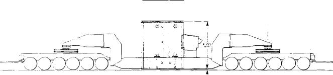
Transporters for the larger transformers consist of two beams which span front and rear bogies and allow the tank to sit between them resting on platforms which project from the sides of the tank. Thus the maximum travelling height is the height of the tank itself plus the necessary ground clearance (usually taken to be 75 mm but capable of reduction for low bridges). Figure 3.55 shows a 267 MVA single-phase transformer arranged for transport.
Smaller transformers, i.e., auxiliary transformers of maximum rating 12.5 MVA, can usually be shipped completely erected and full of oil,
1.8.2 Installation and site erection
In view of their size and weight, most transformers present special handling problems on site. The manufacturer in his works will have crane capacity, possibly capable of lifting up to 260 t based on transport weight limit including vehicle of 400 t, but on-site such lifts are out of the question except in the turbine or reactor hall. Site handling is difficult and must be restricted to the absolute minimum. The transformer plinth therefore should be completed and clear access available, allowing the main tank to be placed directly onto it when it arrives on site. The access road must also be completed, as well as the surface over any space between access road and plinth. Transformer and vehicle can then be brought to a position adjacent to the plinth. The load is then taken on jacks and the transport beams removed. Then, using a system of packers and jacks, the tank is lowered onto a pair of greased rails along which it can be slid to its position over the plinth. The required position of tank on the plinth must be accurately marked, particularly if the transformer is to mate up with metalclad connections on either the LV or HV side.
When the tank is correctly positioned on the plinth, the coolers and pipework are installed. Bushings and turrets which have been removed for transport are fitted and connected, requiring the removal of blanking plates giving access to the tank. Such opening of the tank must be kept to a minimum time, to reduce the possibility of moisture entering the tank; to assist in this, manufacturers of large high voltage transformers provide equipment to blow dry-air into the tank and thus maintain a positive internal pressure.
251
Transformers |
|
Chapter 3 |
||
|
|
|
|
|
|
|
|
|
|
|
|
|
|
|
ON ;LOAD ',VE 5, 7 :id 'ONNES
I jor•LAL GROUND CLEARANCE
Fic, 3.55 Transport arrangements for a 267 MVA single-phase generator transformer
If the transformer has been transported with the tank full of nitrogen, it is necessary to purge this fully with dry air if anyone has to enter the tank.
When all bushings have been fitted, access covers replaced, and conservator and Buchholz pipework erected, preparations can begin for filling with oil. Even if the transformer is not required for service for some months, it is desirable that it should be filled with oil as soon as possible and certainly within three months of the original date of draining the oil. If it is being kept in storage for a period longer than three months, it should similarly be filled with oil.
After completion of site erection, a vacuum pump' is applied to the tank and the air exhausted until a vacuum equivalent to between 5 and 10 mbar can be maintained. Heated, degassed and filtered oil is then slowly admitted to the bottom of the tank in the same way as was done in the works, until the tank is full. Since, despite all the precautions taken, some moisture will undoubtedly have entered the tank during site erection, the oil must then be circulated, heated and filtered until a moisture content of around 2 PPM by volume is achieved for a 400 or 275 kV transformer. For a unit transformer having a high voltage of 23.5 kV, a figure of around 10 PPM is acceptable.
If the transformer has been stored on its plinth full of oil, it will also be necessary to erect the cooler and pipework and fill this with oil before it can go into service. Initially, the cooler will be filled with the main tank isolating valves closed and oil will be circulated via a tank by-pass pipe to dislodge any small bubbles of air which can be vented via the cooler vent plugs. Normally, such tank by-passes are installed by manufacturers as a temporary fitment but it is now CEGB practice to retain them as permanent features on large generator transformers. The oil necessary to bring the level up to minimum operating level can then be added via the conservator filling valve and, once the conservator is brought into operation, the refrigeration
breather may be commissioned for transformers of 132 kV and above. This needs an auxiliary power supply which should, if necessary, be supplied from site supplies, so that the breather can be made alive without waiting for the marshalling kiosk to be installed and energised.
1.8.3 • Site commissioning
Transport to site could well have involved a journey of many hundreds of miles, part possibly by sea. The transformer will have had at least two lots of handling. There is, however, very little testing which can be done at site which can demonstrate that it has not suffered damage. It is therefore vital that such testing as can be carried out at site should be done as thoroughly and as carefully as possible.
The following should be carried out as a minimum:
•Ratio measurement on all taps.
•Phasor group check.
•Winding resistance measurements on all taps.
•Operation of tapchanger up and down its range. Check the continuity of tapped winding throughout the operation.
•Insulation resistance between all windings and each winding to earth. Insulation resistance core-to-earth, core-to-frame and core frame-to-earth.
•No-load current measurement at reduced voltage; very likely this will be done at 415 V and compared with the current obtained at the same voltage in the works.
•Oil samples taken and checked for breakdown strength and moisture content. For a generator transformer for which the oil is to be tested quarterly for dissolved-gas content, this sample would also
252