

reading / British practice / Vol D - 1990 (ocr) ELECTRICAL SYSTEM & EQUIPMENT
.pdfPrinciples of isolated phase busbar operation and forces encountered
CONDUCTOR B FED
ELE%tE ,
FIELD
ELEMENT 0 J |
ELEMENT E |
FIELD |
FIELD |
FIELD INCREASES LEAD
TO JNCRFASED FORCES
BETWEEN ENCLOSURES
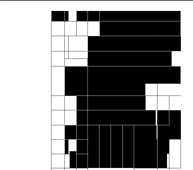
(b) Field distribution in insulated enclosures fOr a 'suppl y and 'return' circuit
tcti Field cancellation in a Continuous enCIOSure arrangement
FIG. 4.6 (coni'd) Radial current flows due to current in an adjacent conductor
by the expression I = I o (1 — cos wt). Consider a parallel adjacent conductor returning the same cur- rent. The magnetic field emitted therefrom would be B = B 0 (1 — cos wt).
From Ampere's Law, the electromagnetic force between them is
F = BI t, where f is the length of conductor, therefore,
F Bolo f' (1 — cos cot) 2 .
Expansion of the expression (1 — cos 0)0 2 gives
— 2cos cot + cos 20.)t), i.e., the force is composed of steady, power frequency and second-harmonic components. These three components of force are each reduced by a different shielding factor. For a detailed
explanation of these shielding factors, the reader is referred to the paper by Wilson and Mankoff [4]; however, the theoretical treatment of these effects is far from conclusive.
Taking into account current decrement, there is a reduction with time of each of the electromagnetic force components, each component having a different decrement rate. The forces produced differ greatly, depending on whether the fault is three-phase or singlephase, the three-phase fault being more onerous.
In principle, the short-circuit electromagnetic forces arise from the combined action of the various forces both between the phases and between the conductor and sheath of the same phase. However, as previously explained, for a continuous 1PB the external magnetic' fields and the resulting forces between conductors are
293
Generator main connections |
Chapter 4 |
|
|
substantially reduced, compared with an unbonded system. Additionally, for a continuous 1PB, the forces between phases are much smaller than those which occur between each conductor and its own sheath.
The magnetic field which exists inside the sheath on a continuous IPB system (as shown in Fig 4.6 (c)), produces a force between the conductor and the enclosure. The force on the enclosure results in the conductor being centralised along a magnetic neutral line. In a suitably designed IPB system, the neutral line is coincident with the axis of the enclosure, thereby
irtually eliminating bending stresses caused by shortcircuit currents. The conductor supports are designed to allow for this slight movement as the conductor takes up its position on the neutral line. The force on the sheath is a repulsion or bursting force which can be represented as internal pressure on the sheath.
The resultant mechanical stresses developed within the installation also depend upon the mechanical frequency response of the structure and will be exacerbated by any resonance that may exist.
The foregoing text has attempted to show that the presence of the sheath in fact reduces forces and to give an awareness of the factors involved: it has not attempted a mathematical prediction of the forces which occur during a short-circuit. Whilst such force calculations may be attempted for straight sections of busbar, they are much more difficult for bends and tee-offs. At these positions the sheath currents vary around the periphery and there is not the benefit of complete mutual compensation of magnetic fields from the conductor and enclosure. Thus, immediately adjacent to bends, very high short-circuit forces exist which tend to straighten out the conductor. There are also higher stray fields which may heat up adjacent steelwork. The 1PB structural support system must therefore be strengthened at bends and other places where the configuration changes.
Mathematical analysis of currents, fields and forces within an IPB system have been attempted, but a main connections design by calculation is not deemed acceptable by the CEGB, for no mathematical method is available that can be used with total confidence. It should be recognised that whilst during normal operating conditions the magnetic field outside the enclosure is practically nil; during fault conditions the field is the difference between the components on the conductor and enclosure which, since there are different ti me elements involved, is very difficult to determine. Consequentl.y, the adequacy of the design is ultimately demonstrated by testing, as discussed further in Section 8 of this chapter.
2.3 Voltage rise
Consider the voltage rise of an electrically-discontinuous IPB enclosure under fault conditions. Since there is no current flow along the whole length of the sheath
installation, large voltages build up across the breaks. It is, therefore, generally necessary to limit the distance between the breaks to a less than desirable length in order to keep these voltages to an acceptable level. With electrically-continuous enclosures, however, the voltage is dissipated in ER drop along the enclosure length as it is generated. Enclosure voltages are consequently held at completely harmless values, even during maximum fault conditions. A typical voltage induced per metre length of continuous enclosure is 3 mV per 1000 A of conductor current.
3 Designing an IPB system
In designing an installation, the factors to be considered include materials, conductor and enclosure dimensions required for specified maximum temperature rises, mechanical strength and structural steelwork requirements. Up until now only naturally cooled systems have been assumed and the predominating factor determining the cross-sectional area and configuration of the conductor for the main connections of a naturally air-cooled busbar is the permissible temperature rise. A tubular conductor has a low skin effect ratio, described later in this section, which helps keep down the AC resistance and hence losses. An adequate crosssectional area must be provided so as to remain within temperature confines proven by experience and not exceeding the temperature limits specified in BS159, i.e., a maximum conductor temperature of 90 ° C. The largest full-load current in the CEGB at the time of writing is 20.1 kA, but this will obviously increase as larger machines are developed. The higher ambient temperatures overseas give rise to lower temperature margins for export designs.
Selection of the most suitable material for IPB construction is generally straightforward, the choice being between copper and aluminium.
At present an unusual situation exists, whereby copper and aluminium are similar in price (usually copper is much more expensive), but aluminium is still the cheaper overall. Copper has approximately three times the weight, but 60% of the resistivity of aluminium. Since aluminium is the poorer conductor, more material is required but, because of skin effect, there is a practical limit to the advantage gained by increasing material thickness. Consequently it is necessary to increase the diameter which has the advantage of increasing the surface area and improving heat dissipation. Aluminium, being much lighter in weight, is easier to handle than copper; this, together with the development of modern aluminium-welding techniques, makes fabrication in aluminium much cheaper than in copper.
The starting point for the designer is therefore to determine the dimensions of the conductor and enclosure appropriate to the specified operating conditions. For the purpose of this exercise, assume the
294

Designing an IPB system
normal cylindrical conductor and enclosure configuration. From experience, an initial conductor diameter and thickness is selected. Ft is then necessary to check the resultant heat generated in the conductor, which
Ltiven by:
W c = I 2 R, |
(4.1) |
W, |
heat generated per unit length, W/m |
|
|
|
= rated RMS conductor current, A |
R L = AC resistance of the conductor appropriate to the temperature of the conductor and the supply frequency, Ci/rn
R. has to take account of skin effect. When AC current is passed down a conductor, the current tends to concentrate on the outer surface. The higher the applied frequency, the thinner is the effective conducting band. The AC resistance R a, is higher than the DC resistance Rd: R ac /Rdc is termed the skin effect ratio, a full study of which was made by Dwight [5]. An extract of one of the curves produced by Dwight for a circular tube is shown in Fig 4.7. It is suitable for aluminum or copper conductors and may be used for all temperatures found in the operational range of the main connections.
The DC resistance is relatively straightforward to
calculate.
At 20 ° C, for a large diameter conductor with a thin wall section, it may be closely approximated using the expression:
Rdc |
Wm |
(4.2) |
|
7rDt |
|
%A here e = resistivity of the material at 20 ° C, Om D = conductor mean diameter, m
t = conductor wall thickness, m
For a conductor operating at a temperature other than 20 ° C, the resistance becomes:
|
Rd, 0 = Rcie20 [I + ot20 (0-20)] |
(4.3) |
\\ here a |
= temperature resistance coefficient at |
|
|
20 ° C |
|
0 |
= temperature, ° C |
|
Having calculated the DC resistance and knowing the ratio t/D, the corresponding effective AC resistance can be determined from Fig 4.7 for the conductor dimension selected. From this, the loss per unit length is calculated, using Equation (4.1).
Next, consider the heat generated in the enclosure due to the enclosure circulating currents. The loss in each phase per metre length is:
W e = 1 R e watts |
(4.4) |
Where l e is the enclosure current, R e is the effective enclosure AC resistance per metre and is calculated from the DC resistance in a method similar to that above for the conductor.
Development of a formula for calculating the enclosure current is complicated by several factors, including the impedance of the bonding bars, the skin effect and the proximity of structural steel or other conducting and magnetic material, as shown by Niemoller [6].
The reader is referred to the IEEE paper [7] for the calculation of IPB losses.
Type testing has shown that it is not unreasonable to assume that the ratio of enclosure current to conductor current (I) to be about 0.95 for an electrically continuous IPB system, i.e.,
W e = 0,91 2 R
In establishing the working temperature, it is assumed that for a natural air-cooled system, almost all the losses (W„ + W e ) have to be dissipated by radiation and convection from the external surface of the enclosure. Clearly the heat that must be dissipated is that quantity which would cause the maximum permitted operating temperature to be exceeded. An approximate expression for natural convection from the outside surfaces of a busbar enclosure, indoors but
not in a compartment, at sea level and normal pressure, based on Dwight et al NI is:
1,A/ c0n = 1360 1.25/Do.25 w/m 2
where W ean = loss dissipated by convection from the enclosure, W/m 2
=average temperature rise of the housing, ° C
D = diameter of enclosure, m
and the energy lost by radiation is given by the StefanBoltzmann expression:
|
|
5.67 |
Wrad |
= |
ke[rl, — rel] A r W/m 2 |
|
|
10 8 |
where Wrad |
|
loss dissipated by radiation from |
|
|
enclosure, W/m 2 |
|
= coefficient of emissivity of the enclo- |
|
|
|
sure surface |
T m |
= average temperature of enclosure |
|
|
|
surface, K |
T o |
= ambient temperature, K |
|
A r |
= effective radiation surface per metre of |
|
|
|
enclosure length, m 2 |
= factor depending on position of phase as described below
295
Generator main connections |
Chapter 4 |
2 0 |
|
|
|
Iii,I1TJJJ1IIIm |
||||||||
|
|
|
|
|
7111111111111 |
|||||||
|
|
|
|
EINNI111111 |
||||||||
1 |
7 |
|
|
11111111111 |
||||||||
1 |
6 |
111111111MINAM |
||||||||||
IN EFFECT RATIO - |
|
MEM= |
|
|
|
|
||||||
|
|
|
|
|
|
|
|
|
|
|
|
|
|
|
|
|
NOME |
|
|
AM |
|||||
1 |
3 |
|
1111111lAW |
|
||||||||
1 |
2 |
1111/11WANW |
|
A |
||||||||
|
|
|
glMr,AMNI MI |
|||||||||
|
|
|
,r,Preairro |
|||||||||
|
|
20 |
40 |
60 |
80 |
100 |
1 20 |
140 |
160 |
180 |
200 |
|
|
|
|
|
|
|
I R 0 |
10 1:3 0 m |
|
|
|
|
|
|
|
|
|
|
|
'11 |
|
|
|
|
|
|
|
|
Fic. 4.7 Skin effect ratio for rods and tubes |
|
|
|
|
|
|||||
Since the radiation from the outer phases will differ from the centre phase, the following factors should be included [9].
For the centre phase k — |
360 — 4a |
A,- |
|
|
360 |
and for the outer phase k = |
360 — 2a |
A r |
|
|
360 |
where a = sin -1 (R/S)
R = external enclosure diameter, m
phasing spacing, m
Total heat loss from the busbar system in W/m run can then be established from (W c,„„ + W rad)7rD.
Factors not included in the equations which will affect heat dissipation both by convection and radiation from the enclosure are physical arrangements, neighbouring structures and surface finish. It must be borne in mind that hot spots can occur, particularly at the ends of busbar runs where connections are made to auxiliary plant. This occurs because of poor current sharing in unsymmetrical current-carrying connections, as will be discussed later, or from the concentration of circulating currents. Experience suggests that the conduction of heat from associated plant, namely the generator itself and the transformer bushings into the connections, should also be considered.
Summarising, (a) the heat generated (W/m run) in the conductor and enclosure with
296

Forced cooling
the dimensions initially selected from experience can be calculated, i.e., W e + W.
Then,
(b) allowing for specified temperature rises of conductor above enclosure and of enclosure above ambient, the quantity of heat dissipated per metre length by the selected installation can be calculated, i.e., ( Wcon + Wrad) 7r D
The values of (a) and (b) are compared and, if they are not close the dimensions are revised and the pro-
cess repeated.
In the CEGB, the temperatures specified at present
are
•Conductor maximum temperature 90 ° C.
•Enclosure maximum temperature 65 ° C.
•Internal air maximum temperature 70 ° C.
•Ambient temperature 40 ° C.
Having established the dimensions of the IPB system from load current thermal conditions, the designer must then consider fault conditions.
Generally speaking, for a main run of IPB, the busbars are so large for continuous current-carrying requirements that the thermal requirements for shortcircuit conditions are more than catered for. How- e‘er, for a unit transformer or other tee-off, the continuous current rating is small but the fault current rating is very high indeed. Here, the fault current specified may influence the busbar dimensions that are required because of its thermal effects, therefore requiring repeat calculations to determine temperature rises during fault.
However, the major design concern arising from fault considerations is mechanical strength. The deigner must provide a suitable support arrangement for he conductor and enclosure to ensure that the final :,iructure is of adequate strength to withstand the forces ihat are exerted on the system during fault conditions. f he forces have been briefly explained in Section 2 Or this chapter. For the conductor, the designer is looking to provide sufficient support to:
•Prevent deflection between supports due to forces between conductors and between conductor and enclosures during fault.
•Prevent damage due to 'straightening out' forces sshich occur at bends during fault.
•Prevent damage due to 'knife switch' forces at the tee-off positions, again due to the conductor at-
tempting to straighten along the line of maximum fault current.
An adequate structural support is required for the enclosure to withstand the resultant static and dynamic loadings that the system will experience during fault.
The present view of the CEGB is that there is no mathematical approach to solving these problems that can be used with confidence. The designer may from his own experience use simple force calculations as a starting point. Reference [10] is such a suitable starting point. Ultimately, however, before a design can be considered acceptable, a full set of short-circuit and earth fault type-test evidence is required to substantiate the design, as identified in Section 8 of this chapter.
Finally, the stray magnetic fields surrounding the main connections, as already described, can give rise to inductive heating of adjacent steelwork. For an IPB system, there is unlikely to be any problem with systems carrying less than 8000 A. However, above this, care should be exercised. It is not only structural steelwork which may cause problems, but also piping and pipe hangers, gas and air ducts as well as stairs and handrails. Heating of such components could ignite adjacent flammable material, be a danger to personnel, cause structural stresses due to restrained expansion, and of course, incur additional running costs due to the losses.
Analysis of this problem is most difficult and use is made of existing heat run tests. If the reader wishes to pursue the problem, an approach is described by Swerdlow and Buchta [II] and there are some guidelines regarding spacing of adjacent steelwork given in Section 7.18 of this chapter.
Various methods are available to reduce the temperature rise of structural members, the use of shielding plates being favoured by the CEGB.
4 Forced cooling
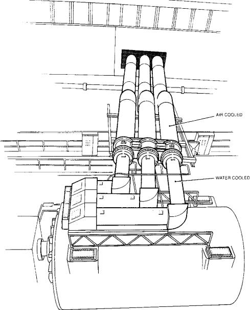
The optimum design of an IPB installation is determined by considering the capital cost, plus the cost of generating the associated losses. In order to satisfy the temperature balance requirements described in Section 3 of this chapter, naturally-cooled connection systems greater than 800 MVA, though practical, would require excessive space and consequently their cost would be high. For connections rated above 800 MVA, unless a much higher generator voltage is thought worthwhile, consideration must be given to forced cooling of the connections by some method. With reference to Fig 4.1, which shows a typical natural aircooled connection installation, it can be seen that the tee-off connectors from the main busbar carry a relatively low current, i.e., the high current flow is from the generator to the generator transformer. In considering the cross-sectional area of these components, it is clear that only the main run can justify forced cooling, the tee-off design being instead determined by the maximum fault current which could flow in it. Though it is unlikely that the use of forced
297
Generator main connections |
Chapter 4 |
|
|
cooling below 8 kA would be economic, the limit for natural cooling, depending upon generator voltage, is reached at currents of 25-30 kA and, for currents in excess of this, the busbars are normally forcedcooled.
Therefore, if forced cooling is to be considered, the heat balance approach taken in Section 3 of this chapter will have to include a calculation of the heat removed by forced cooling. Such calculations will depend very much on the design of the installation.
The obvious choice of cooling medium is either air or water. In considering the economic case for forced cooling, the saving of material is offset by a possible increase in system losses, the additional cost of cooling equipment, routine inspection and maintenance of motors, fans, pumps, pipework, heat exchangers, etc. The value assigned to the losses/kW generated will obviously influence whether to force-cool the system if, in fact, temperature rise has not itself dictated its use.
Once reliance is placed on forced cooling, any failure which might occur on the coolant plant would necessitate a consequential reduction in generated output, so it is desirable to aim for a high naturally-cooled current-carrying capacity, i.e., with the cooling plant out of commission. It is also necessary to specify the operating time at full-load current with the cooling plant shut down. The more common forced cooling systems are described below, though work is being carried out on the use of some of the newer insulating materials, for example, SF6 gas.
4.1 Forced air cooling
A typical forced air system would comprise fans, heat exchangers, dampers and air filters arranged such that there is one set of equipment for each machine unit. Cooled air is blown from the heat exchanger, usually a finned water-cooled coil, down the busbar run between the enclosure and the conductor and returned to the heat exchanger, thereby forming a closed circuit. Such schemes are used extensively in the USA and, for a normal installation, air may enter the centre phase of the connection system, travel along it and return back through the outer two phases, sufficient air volume being used to ensure that the final air temperature does not exceed the maximum allowable touch-temperature of the enclosure. The cooling equipment may be located at any point along the connections system but the most economical position is midway between the generator and its transformer. Since the cooling air passes through the entire system, splitting the total cooling air volume in the centre phase and forcing it in opposite directions results in less overall system resistance, therefore requiring less fan power. The air must be cleaned and dried to reduce the risk of faults and all the associated equipment, including the fans, must be duplicated to ensure availability (2 x 100 07o or 3 x 50 01o).
In addition, if the cooling air leaves one phase and enters another, then de-ionisation plant is required to prevent ionised gases produced by a system fault entering other phases, thereby extending its severity.
Air has the obvious advantage of being cheap and plentiful but because it has a relatively low specific heat and density, large quantities are required to remove the heat and the fan requirement is proportional to the cube of the flow rate. This disadvantage can be overcome if liquid cooling of the conductor is considered.
The rating for a forced air cooled installation with cooling plant shut down would probably be in the region of I hour and the naturally cooled rating would be approximately 60% of full load.
4.2 Liquid cooling
It may be considered that the obvious choice is to extend the transformer cooling oil into the main connections conductor, as oil has a low specific heat and density compared with water. However, the fire risk associated with oil within the power station buildings is unacceptable. It is also considered unacceptable to risk the integrity of the transformer insulation by involving any other plant in the oil circuits — even delta boxes (see Section 5.4 of this chapter). Demineralised water has been used as the cooling medium in the generator stator for many years and the techniques have been well proven. It would therefore be possible to extend this system to include the generator main connections or, alternatively, to install a separate water cooling system.
4.3 Water cooling
Since water has a better thermal conductivity and specific heat than air, the temperature rise of a main connections installation of this type can be more easily controlled by adjustment of the coolant flow than in an air cooled system. The material cross-sectional area provided in these circumstances is then based on consideration of the capitalised cost of the conductor losses (see Chapter 3, Section 2.1.5) against the capital cost of the conductor itself, together with the mechanical strength requirements for fault conditions.
Clearly the water in the conductor is at the same potential as the conductor itself, so some form of potential dropping device is required between the conductor and remainder of the hydraulic circuit, which should be at earth potential. This device is a resistance column consisting of a long pliable connector of non-conducting material having a small cross-sectional area, thereby providing a high-resistance path to low currents. The cooling water then flows within a closedcycle cooling system with a heat exchanger, itself indirectly cooled by water. The cooling system may be incorporated in the stator cooling circuit, if the heat
298

System description
oenerated in the connections system is small relative
-t o the heat removed from the stator windings.. ft will then be found most convenient to connect the hydraulic cooling circuits in series. The conductor opcrating temperature should then be only slightly above the cooling water temperature.
Joints between sections of conductor are welded, the welds, apart from requiring the necessary mechanical ,irength, being watertight. Where conductors are connected to the plant, braided flexible connectors are used to allow for expansion and provide vibration immunity from that plant, the terminal palms themselves being within the connections, bridged by the water cooling circuit, the bridge being of non-conduct- ing material. Heat conduction to the conductor helps keep down the temperature of the flexible connections.
A water cooled system would have no short-time full-load rating and a naturally cooled rating in the event of loss of forced cooling, of approximately 20%.
The major disadvantages of a water system, therefore, are the substantial reduction in unit output if cooling is lost and the danger of an earth fault developIna if a water leak occurs. The reliability of the water seals is therefore very important.
5 System description
A schematic drawing of a typical main connections system is given in Fig 4.8.
The generator windings are star-connected, the star point being formed outside the generator, so there are two generator terminals for each phase. The output of the generator is taken from the line end of the phase windings, the star point being formed at the neutral end of the windings. It is desirable, for ease of making connections to the generator, to have these two ends located as far apart as possible, their relative positions being dependent on the generator manufacturer's frame design.
The generator transformer is wound in delta/star configuration, the LV side being the delta winding. This transformer may consist of one three-phase tank or three single-phase tanks. The delta connection of the transformer can either be formed below oil or, as is now more common, can be made part of the main connections system to maintain phase isolation. An oil delta is not nowadays favoured since it allows any contaminated oil due to a fault in one phase to circulate into the other phases.
Connections are taken from the main busbar to the HV terminals of unit auxiliary transformers and the system voltage three-phase earthing transformer (if fitted), discussed in Section 11 of this chapter. This connection, known as a tee-off from the main busbar, again maintains phase isolation up to the bushings, the transformers themselves generally being housed in three-phase tanks.
There is a requirement to monitor voltage conditions on the main connections system for various purposes,
|
|
|
|
|
|
|
|
|
|
|
|
|
|
|
GENERATOR |
IPO |
||||||||
|
|
|
|
NEUTRAL |
LINE |
|
|
|
|
|
|
|
DELTA |
|
|
|||||||||
|
|
|
|
|
|
|
|
|
|
CIRCUIT BREAKER |
|
|
||||||||||||
|
|
|
|
END |
END |
|
|
|
|
|
|
|
|
|
|
|||||||||
|
|
|
|
|
|
|
|
|
|
|
(IF APPLICABLE) |
|
|
|
|
|
||||||||
|
|
|
|
|
|
|
|
|
|
|
|
|
|
|
|
|
|
|
|
|||||
|
|
|
|
|
|
GENERATOR |
|
|
|
|
|
|
|
|
|
|
|
|
|
|
|
|
|
GRID |
|
|
|
|
|
|
|
|
|
|
|
|
|
|
|
|
|
|
|
|
|
|
|
||
|
|
|
|
|
|
|
|
|
|
|
|
|
|
m |
X m |
|
|
|
|
|||||
|
|
|
|
|
|
|
|
|
|
|
|
|
|
|
|
|
|
|
VOLTAGE |
|||||
|
|
|
|
|
|
|
|
|
|
|
|
|
|
|
|
|
|
|
|
|
|
|
|
|
|
|
|
|
|
|
|
|
|
|
|
|
|
|
|
|
|
|
|
|
|
|
|
|
|
|
|
|
|
|
|
|
|
|
|
|
|
|
|
|
|
|
|
|
|
|
|
|
||
|
|
|
|
|
|
EARTH SWITCHES |
|
|
|
|
|
|
|
|
|
|
|
|
|
|
GENERATOR |
|||
|
|
|
|
|
|
|
|
|
|
|
|
|
|
|
|
|
|
|
|
|||||
|
|
|
|
|
|
|
|
|
|
|
|
|
|
|
VOLTAGE |
|
TRANSFORMER |
|||||||
|
|
|
|
|
|
|
|
|
|
|
|
|
|
|
|
|
|
|
||||||
|
|
|
|
|
|
|
|
|
|
|
|
|
|
|
|
|
|
|
||||||
|
|
|
|
|
|
|
|
|
|
|
|
|
|
|
TRANSFORMER |
|
|
|
|
|||||
STATOR |
|
|
|
|
|
|
|
|
|
CUBICLE |
|
|
|
|
||||||||||
NE |
TL |
|
|
|
|
|
|
|
|
|
|
|
|
|
|
|
|
|
|
|
||||
E ,1",="!+NG |
|
|
|
|
|
|
|
|
|
|
|
|
|
|
|
|
|
|
|
|||||
RES SCR |
|
|
|
|
|
|
|
|
|
|
|
|
|
|
|
|
|
|
|
|||||
r--
E E E
|
SYSTEM |
|
|
:_ CC.A. - C.N OF PROTECTION CM |
UNIT |
||
|
EARTHING |
TRANSFORMER |
|
|
TRANSFORMER |
|
|
|
{IF APPLICABLE) |
|
|
FIG. 4.8 Generator main connections — simplified schematic
299
Generator main connections |
Chapter 4 |
|
|
including generator synchronising, tariff metering, instrumentation, automatic voltage regulation and protection schemes. There is also the requirement to monitor current conditions, for example, for protection purposes. The requirement to monitor voltage is met by the connection of voltage transformers (see Section 7.8 of this chapter) onto the main connections via a further tee-off similar to the auxiliary transformer teeoff described earlier. Up to four voltage transformers per phase may be required, mounted within cubicles which maintain the phase isolation of the system. Current transformers (see Section 7.9 of this chapter) are mounted in the main connections runs, in positions dependent upon the protection scheme adopted.
Other equipment may be included in the main connections system, such as connections to generator excition plant, earthing devices and to the generator circuit-breaker. These will be discussed later.
The various features of the main connections system are now described in greater detail.
5.1 Line end
The position on the generator of the line terminals depends on the generator manufacturer but the two obvious locations are either above or below the machine. Both positions have advantages and disadvantages for the main connections system. In all cases, consideration should be given to generator rotor removal without the necessity to dismantle any of the main connections installation. Any support given to the connections should be independent of the machine to prevent the transmission of vibration.
Where the main connections leave the generator from above, the overall height of the machine is obviously increased. This may increase the height of the turbine hall crane-rails, and hence the turbine hall itself, thereby creating a cost penalty. Also, connections above the machine and their support structures can, if incorrectly designed, suffer fatigue due to vibration excited by the generator.
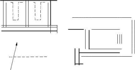
If, how ever, the line connections are below the generator, there are obvious obstructions which require to be negotiated, for example, the generator foundations, generator/turbine auxiliary equipment, access ways, etc. Clearance from such obstructions can dictate whether the busbars lie side-by-side or in trefoil configuration. Other practical issues to be resolved at the generator line-end terminals are heat dissipation due to confined space, access for stator cooling pipework, prevention of water ingress and spacing of the line terminals, which may be arranged on the generator in an in-line or trefoil configuration. Where space is restricted, it may be necessary to consider the use of specially designed sections of busbar having reduced conductor and sheath dimensions, a terminal box arrangement with phase segregation, use of other than circular cross-section busbars or a short water-cooled
section (see Fig 4.9). In the case of a segregated terminal box the phase barriers should be of the same material as the box (probably aluminium) and earthed to ensure that there is an earth plane between phases which reduces the risk of phase to phase faults. Phase to earth faults produce fault current which is restricted by the neutral earthing equipment. However, there is always the possibility of an earth fault developing into a phase to phase fault which causes much greater damage; it is therefore preferable to use a phase isolated system if possible.
Early design co-ordination at the interface connection onto the machine is necessary to solve the problems associated with terminal spacing and ensure that the specified impulse-withstand level can be achieved. To allow for possible hydrogen leakage through the generator terminals, a complete bushing-type seal should be provided in the main connections run to limit the volume into which hydrogen could possibly enter. This volume at the generator should then be suitably ventilated to ensure that approximately four air changes per hour can take place within the enclosure to reduce the risk of build-up of hydrogen in air, which could form an explosive mixture.
5.2 Neutral end
The method of generator stator neutral earthing is described in Section 11 of this chapter. An example of stator neutral earthing is shown in Fig 4.10.
Again, depending on the machine manufacturer, the generator neutrals can be situated on the top or the bottom of the generator. It is obviously more straightforward if they are positioned below, as all the stator neutral earthing equipment described can then be housed within a single module supported on independent steelwork adjacent to the neutral terminals. If the terminals are located on the top of the machine, while the star connection can be made easily, vibration may be excessive if the stator neutral earthing transformer is mounted on the machine frame or support and therefore it should be located away from the star bar. Vibration would certainly prevent the resistor being mounted on the machine. Either a cable connection would be required (which is undesirable as it is vulnerable to damage) or, alternatively, a short section of IPB could be used and the transformer located away from the star bar. Equipment installed on the top of the machine can raise the height of the turbine hall with a consequential cost penalty. Due consideration should be given to preventing ingress of water into the neutral end equipment, since ventilation must be provided for the resistor to dissipate the heat produced during an earth fault.
5.3 Tee-offs
Tee-off connections are used to connect auxiliary transformers and voltage transformers to the generator
300
System description
Fic. 4.9 Specially designed busbar sections for use in space-restricted areas
voltage system. The power requirements of a voltage iransformer are minimal so for these tee-offs, but not others, a reduction in current-carrying capacity is acceptable, provided that a suitable fuse is mounted immediately adjacent to the tee-off connection to deal v.ith faults. CEGB uses a 10 A fuse at this position. Downstream of this fuse (a distance generally of the order of a few metres between the main and the VT cubicle), the tee-off need only be designed to be mechanically sound. To ensure that an adequately strong
is offered, the CEGB specify a continuous rating A for this section.
Tee-off enclosures can be bonded into the main run or isolated and treated as a separate section of IPB,
the choice being made by the designer and fault tested as a system.
5.4 Delta connections
The connection of the delta on recent stations, e.g., Littlebrook D and Heysham 2, is made by using airinsulated IPB and, since the current flow in each delta arm is less than the line current by a factor 1/../3, the dimensions can be reduced appropriately from that of the main run, though the system highest voltage is the same. To ensure that the correct phasor grouping of the transformer is achieved, correct phase sequence
301
Generator main connections |
Chapter 4 |
|
|
|
|
|
GENERATOR |
M LOCATION OF PROTECTION C% |
|
TERMINAL PLATE |
|
FLEXIBLE |
1500V |
CONNECTION |
|
STAR BAR |
|
32kV |
NE,JTRAL |
STATOR |
ENCLOSURE |
NEUTRAL EARTHING |
|
MODULE |
FIG. 4.10 Stator neutral earthing
of the LV and HV phases for the installed transformer winding terminals is essential (see Chapter 3, Transformers).
5.5 Excitation busbars
Some generator designs use rotating excitation equipment, whereas others use separately-located stationary equipment. In the latter, the electrical connection between the exciter equipment and the machine is an 1PB system similar to that of the generator voltage system, though obviously running at the much reduced design voltage of 3.6 kV and maximum continuous current rating of 5000 A (AC or DC) (1988), with consequential reduction in size. Typically, the installation
ould comprise AC and DC connections forming a system as shown in Fig 4.11, with a normal operating voltage of below 650 V, connecting the main exciter, the exciter rectifier cubicle, the field suppression switch, and the generator slipring and brushgear enclosure.
5.6 Earth bar
The earth bar system is quite complicated since all associated auxiliary equipment must be earthed in a manner such that no circulating-current paths can occur; a typical system is shown in Fig 4.12. For the purpose of its design, it is assumed that the neutral earthing equipment (see Section 11 of this chapter) has been shorted-out due to a coincident fault and that the earth fault current is unrestricted. The earth path must be rated to carry the maximum earth fault current from any part of the connections system where an earth fault could occur back to the generator. For
an installation which includes generator voltage switchgear, an additional earth is incorporated on the system to provide the earth when the switch is open. The earth path must be of low resistance to prevent a rise in potential on any part of the system (during a fault) above a level which could cause a danger to personnel. With the system operating normally, the CEGB specify this level as 55 V and, during fault conditions, 430 V is specified as the maximum rise of earth potential to comply with telecommunication directives within the UK. However, if faults can be cleared within 200 ms a voltage rise of 650 V is acceptable.
If no earth path were provided, the return earth fault current would follow a random path (or paths) of low resistance back to the machine. These routes may be tortuous and not adequate to carry such large currents. The provision of a designed earthing system directs the flow of earth fault current along a predetermined route, thereby containing all earth fault currents within the main connections system. The earth path comprises an earth bar of adequate cross-sectional area connected to plant by flexible leads and held at the potential of the station earth network. Since the earth bar would provide the lowest resistance path to earth fault currents, the earth bar redirects the fault current away from the station earth system which, in any case, would not normally be rated for such large currents.
The earth bar is not screened by an enclosure; when earth fault current flows, large external magnetic fields are produced, so it is usual to position the bar some distance from the main busbar installation to prevent excessive forces being produced. The earth bar has to negotiate many obstacles on its route, e.g., civil works, auxiliary plant, etc., so that it includes
302