

reading / British practice / Vol D - 1990 (ocr) ELECTRICAL SYSTEM & EQUIPMENT
.pdf
|
|
|
|
|
General design and construction |
|
|
|
|
||||
balanced three-phase system of voltages is zero, no |
clamping can be applied to the windings to compress |
|||||
return limb is necessary in a three-phase core and limbs |
them down to their correct length. |
|||||
and yokes can have equal cross-sections. In order to |
These principles will apply to the cores of all the |
|||||
li mit the extent to which the flux path cuts across the |
core-type transformers shown in Fig 3.9. Single-phase |
|||||
grain of the oriented material, corners of laminations |
cores may have windings on both limbs, in which case |
|||||
|
|
|
|
0 |
limbs and yokes will probably have the same cross- |
|
are usually cut on a 45 mitre. Plates at these mitred |
||||||
corners must be overlapped so that the flux can transfer |
sectional area. Alternatively these may have one wound |
|||||
to the adjacent face rather than cross the airgap which |
central limb, with two, three or four return yokes. The |
|||||
is directly in its path. The overlaps are formed by alter- |
first arrangement tends to result in the lowest iron loss |
|||||
nating different lengths of plates in successive lays (Fig |
for a given rating but, since the number of windings |
|||||
3.10). |
|
|
|
is doubled, their cost is increased. The use of a number |
||
|
|
|
of return yokes, as in the other arrangements, means |
|||
|
|
|
|
|
||
|
|
|
|
|
that the required cross-section can be achieved with |
|
|
|
|
|
|
a smaller yoke depth, thus reducing the height for |
|
|
|
|
|
|
transport. The three-phase equivalent of this is the |
|
|
|
|
|
|
five-limb core which can be used to reduce the travel- |
|
|
|
|
|
|
ling height of a three-phase unit at the expense of |
|
|
|
|
|
|
iron losses. It should be noted that, provided transport |
|
|
|
|
|
|
weight and height limitations permit, the yoke depth |
|
|
|
|
|
|
can be increased to give a greater cross-section, and |
|
|
|
|
|
|
hence reduced flux density, compared with the legs. |
|
|
|
|
|
|
This results in a reduction in specific core loss in the |
|
|
|
|
|
|
yokes which is greater than the proportional increase |
|
|
Fin. 3.10 Arrangement of mitred joints in core |
in yoke weight, hence in a net reduction in total core |
||||
|
loss. This is economic if the saving in the cost of the |
|||||
|
|
|
|
|
||
|
|
|
|
|
iron loss over the lifetime of the transformer is greater |
|
|
The core is |
built horizontally by stacking lamina- |
than the cost of the extra material. |
|||
|
Before concluding the description of core construc- |
|||||
tions, usually two or three per lay, on a jig or stillage. |
||||||
tion, mention should be made of the subject of core |
||||||
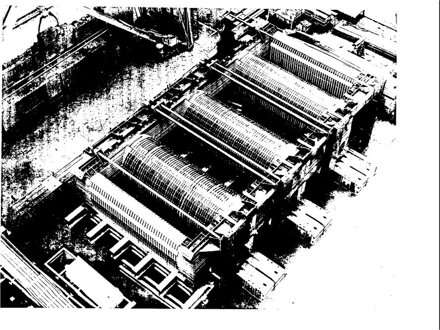
Figure 3.11 shows a large core being built in the |
||||||
earthing. Any conducting metal parts of a transformer, |
||||||
manufacturer's |
works. Clamping frames for top and |
|||||
unless solidly bonded to earth, will acquire a potential |
||||||
bottom yoke will be incorporated into this stillage |
||||||
in operation which depends on their location relative |
||||||
but it must also provide support and rigidity for the |
||||||
to the electric field within which they lie. In theory, the |
||||||
li mbs until the |
core has been lifted into the vertical |
|||||
designer could insulate them from earthed metal but, |
||||||
position for the fitting of the windings. Holes through |
||||||
in practice, it is easier and more convenient to bond |
||||||
the laminations of cold-rolled grain-oriented material |
||||||
them to earth. However, in adopting this alternative, |
||||||
cause deviations in the flux path and increase losses. |
||||||
there are two important requirements: |
||||||
Punching of these holes also creates local stress con- |
||||||
|
||||||
centrations which increase losses so that, although bolts |
• The bonding must ensure good electrical contact and |
|||||
through punched holes were the standard means of |
remain secure throughout the transformer life. |
|||||
providing clamping for cores built of hot-rolled steel, |
• No conducting loops must be formed, otherwise |
|||||
it is now practice to minimise bolt holes or, if possi- |
||||||
ble, to eliminate them entirely. Bolts securing top and |
circulating currents will result, creating increased |
|||||
bottom frames will be designed to pass around the |
losses and/or localised overheating. |
|||||
yokes rather than through them, as shown in Fig 3.12. |
|
|||||
Without clamping bolts the legs have no rigidity at all |
Metalwork which becomes inadequately bonded, |
|||||
until the windings have been fitted. This fitting requires |
possibly due to movement from shrinkage or vibration, |
|||||
the removal of |
the top yoke which will usually have |
creates arcing which will cause breakdown of insula- |
||||
been placed in |
position during building to provide |
tion oil and will produce gases which may lead to |
||||
rigidity and alignment for the core. The legs are normal- |
Buchholz relay operation (see Section 1.6.2 of this |
|||||
ly clamped as tightly as possible by steel bands, which |
chapter), and can thus be very troublesome in service. |
|||||
are stripped |
off, starting from the top of the leg, as |
The core and its framework represent the largest |
||||
the windings |
are lowered into place. Once in place |
bulk of metalwork requiring to be bonded to earth. |
||||
these windings, which are built onto a hard synthetic |
On generator transformers, connections to core and |
|||||
resin bonded |
paper (SRBP) tube, ensure that the leg |
frames are individually brought outside the tank via |
||||
remains rigid. The top yoke can then be replaced, |
3.3 kV bushings and are then connected to earth ex- |
|||||
suitably interlaced into the projecting ends of the leg |
ternally. This enables the earth connection to be dis- |
|||||
laminations, followed |
by the top core frames. Once |
connected during maintenance so that core insulation |
||||
these have been fitted, |
together with any tie bars, axial |
resistance checks can be carried out. |
||||
203
SJ WJ OISUeJI
FIG. 3.11 Large core being built (GEC Alslhont) (see also colour photograph between pp 496 ancl 497)
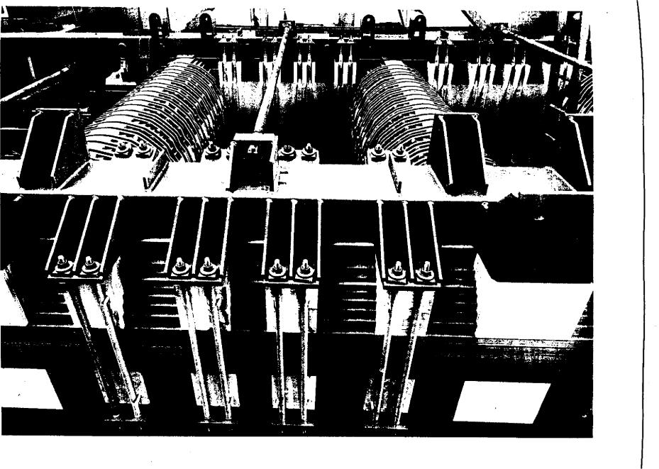
FIG. 1.12 Completed core, showing rrante bolts (GEC Alsthom) (see also colour photograph between pp 496 and 497)
construction and design General
Transformers |
Chapter 3 |
|
|
1.4.2 Transformer windings
In describing the basic principles of a two-winding transformer, it has been assumed that the windings comprise a discrete primary and secondary, each being a cylinder concentric with the wound limb of the core which provides the low reluctance path for the interlinking flux. Whether of single-phase or three-phase construction, the core provides a return flux path and must, therefore, enclose the winding, as shown in Fig 3.13. As well as dictating the size of the transformer in total, the size of the windings thus dictates the size of the window that the core must provide, and hence the dimensions of the core and the iron losses are determined. The designer must aim for as compact a winding arrangement as possible. Militating against this are the needs to provide space for cooling ducts and insulation, and also to obtain as large a copper
cross-section as possible in order to minimise load losses.
|
|
|
|
|
|
|
|
|
|
|
|
|
|
|
|
|
|
|
|
|
|
|
|
|
|
|
LV |
|
HV |
|
HV |
|
|
|
|
HEIGHT |
||
|
|
|
|
|
|
|
|
|
|
|
|
|
|
|
|
|
|
|
|
|
|
|
|
|
|
|
|
|
|
|
|
|
|
|
|
|
|
|
WIDTH
CORE WINDOW
Flu. 3.13 Arrangement of windings within core window
some manufacturers attempted some experimental use of aluminium, but its higher resistivity greatly complicates the designer's problems. It necessitates a greater cross-section of conductor and a larger number of cooling ducts; these in turn cause a large increase in winding size, which increases the size of the core. In addition, the increased winding size increases impedance, requiring a further increase in frame size counteract this (Section 1.3.2 of this chapter) so iron losses are increased still further, risking a runaway situation. Unlike other areas of power station plant (e.g., cables) it is exceedingly unlikely that aluminium will ever become a serious rival to copper for transformers.
Winding conductors are normally rectangular in section (Figs 3.14 and 3.1$). They have a far better winding space factor compared with circular conductors and are used exclusively, except for the very small transformers where both circular conductors and, on occasions, foil windings are used. These will be discussed further in Section 2.4 of this chapter which deals with auxiliary transformers.
Winding strands must be insulated from each other within a winding conductor and, of course, each conductor must be insulated from its neighbour. This is achieved by wrapping the strands helically with paper strip, and at least two layers are used, so that the outer layer overlaps the butt joints in the layer below. The edges of the copper strip are radiused in order to assist in paper covering. This also ensures that, where strands are required to cross each other at an angle, there will be less 'scissor action' tending to cut into the insulation. Where conditions demand it, many layers of conductor insulation can be applied and the limit to this is determined by the need to maintain a covered cross-section which can be built up into a stable winding. This demands that, particularly when they are to have a thick covering of insulation, winding conductors should have a fairly flat section, so that each can be stably wound on top of the conductor below. This usually means that the axial dimension of the strand must be at least twice, and preferably two and a half times, the radial dimension.
1.4.4 Low voltage windings
The following sections will aim to describe how to achieve the best compromise between these conflicting objectives in practice.
1.4.3 Winding conductors
Before discussing the details of transformer windings further it is necessary to look in some detail at winding conductors.
Power station transformers use copper windings almost exclusively and the detailed requirements for them are set down in BS1432 [3]. During the late 1960s, there was a very sharp rise in the price of copper and
Although the precise details of the winding arrangements vary according to the rating of the transformer, the general principles remain the same throughout most of the range of power station transformers and it is therefore convenient when describing these windings to consider specific cases. It is also useful to the reader to be able to relate the descriptions given to practical situations.
Generally, a power station transformer is rated to match the associated low voltage switchgear. At II kV, 3.3 kV and 415 V, switchgear ratings extend up to about 3000 A. For the low voltage (LV) winding of most transformers, therefore, this is the order of the
206
General design and construction
CORE LIMB
RADIAL DUCTS
BETWEEN TURNS
MEM "9111IMIN
EEEEE ELL
RADIAL DUCTS
BETWEEN DISCS
|
|
|
|
|
|
|
LV |
I |
|
HV |
|
|
|
|
|
|
|
WINDING |
|
|
WINDING |
|
|
|
|
|
|
|
(SINGLE I |
|
(CONTINUOUS |
|
|
|
|
|
|
|
|
LAYER 1 |
|
DISC) |
|
AXIAL DUCTS |
|
|
|
HELICAL) |
|
|
|
|||
|
|
|
|
|
|
|||||
|
|
|
|
|
|
|
|
|
|
|
|
|
|
|
|
|
|
|
|
|
|
|
|
|
|
|
|
EEEEEE |
|
|
|
|
|
LV TURN 3 |
|
|
|
||||||
|
|
|
|
|
|
|||||
|
|
|
|
|
|
|
|
|
|
|
|
LV TURN 2 |
t |
|
|
|
|
|
|||
|
|
|
|
|
|
|
|
|
|
|
|
LV TURN |
|
|
|
|
|
|
|
||
ONE TURN OF LV HAS |
HV HAS 5 TURNS PER MC |
la STRANDS IN PARALLEL |
2 STRANDS IN PARALLEL PER TURN |
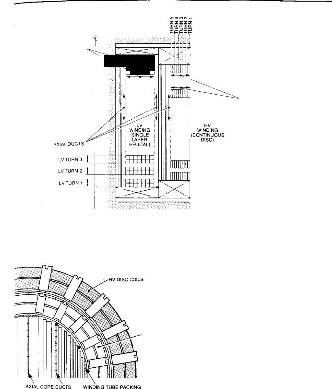
FIG. 3.14 Section of I N and HV windings
HV
LV
LV COIL
CORE
FIG. 3.15 Transverse section of core and windings, showing axial cooling ducts
current involved. (There are transformers outside this range, of course; for a 600 MVA generator transformer, the LV current is of the order of 15 000 A.)
The voltage ratio is usually such that the current m the high voltage (HV) winding is an order of mag-
showing radial and axial cooling ducts
nitude tower than this, say, up to about 300 A. In most oil-filled transformers, the current density is between about 2 and 4 A/mm 2 , so that the conductor section on the LV winding is of the order of, say, 50 mm x 20 mm and that on the HV winding, say, 12 mm x 8 mm. As explained in Section 1.3.1 of this chapter, the volts per turn in the transformer is dependent on the cross-sectional area of the core or core frame size. The frame size used depends on the rating of the transformer but, since, as the rating increases the voltage class also tends to increase, the volts per turn usually give an LV winding with a hundred or so turns and a HV winding with a thousand or more. In practice, the actual conductor sizes and the numbers of turns used depend on a good many factors and may therefore differ widely from the above values. They are quoted as an indication of the differing problems in designing LV and HV windings. In the former, a small number of turns of a large-section conductor are required; in the other, a very much larger number of turns but of a much more manageable cross-section are involved, and it is these factors which determine the types of windings used.
The LV winding is usually positioned nearest to the core, unless the transformer has a tertiary winding (which are normally of lower voltage) in which case the tertiary will occupy this position;
207
Transformers |
Chapter 3 |
|
|
•The LV winding has the lower test voltage and hence is more easily insulated from the earthed core.
•Any tappings on the transformer are most likely to be on the HV winding (see below), so that the LV windings will only have leads at the start and finish and these can be easily accommodated at the top and bottom of the leg.
The LV winding is normally wound on a tube of insulation material and this is almost invariably of synthetic-resin-bonded paper (SRBP). This material has high mechanical strength and is capable of withstanding the high loading that it experiences during the winding of the large copper-section coils used for LV windings. Electrically, it will probably have sufficient dielectric strength to withstand the relatively modest test voltage applied to the LV winding without any additional insulation.
The hundred or so turns of the LV winding are wound in a simple helix, using the tube as a former, so that the total turns occupy the total winding length, although occasionally, for example, if this winding is to be connected in interstar, the turns might be arranged in two helical layers so that two sets of winding ends are accessible at the top and bottom of the leg.
Between the winding base tube and the winding conductor, axial insulation-board strips are placed so as to form a duct for the flow of cooling oil. These strips are usually of a dovetail cross-section (Fig 3.15) so that spacers between winding turns can be threaded onto them during the course of the winding. Axial strips are usually a minimum of 8 mm thick and the radial spacers 4 mm. The radial cooling ducts formed by the spacers are arranged to occur between each turn or every two turns, or even, on occasions, subdividing each turn into half-turns.
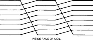
1.4.5 Transpositions
It has already been explained that the winding conductor of a LV winding having a large copper crosssection, is subdivided into a number of sub-conductors, or strands, to reduce eddy current loss. The eddy currents were said to result from the radial differences in leakage flux between the inside and the outside of the windings. The induced EMFs causing circulation of these eddy currents can best be equalised and the eddy currents reduced if each conductor occupies all possible positions equally in its true length. It is therefore necessary to transpose the winding conductors periodically throughout the length of the winding.
There are various methods of forming conductor transpositions, but typically these might be arranged as shown in Fig 3.16. If the winding conductor has, say, eight sub-conductors, then eight transpositions are needed over the winding length. These are carried out by moving the inner conductor sideways from
INNER STRAND MOVES TO OUTSIDE.
ALL OTHER STRANDS MOVE DOWN
ONE POSITION
F[G. 3.16 Developed section of an eight-strand conductor showing transposition of strands
below the other seven, which then each move radially inwards by an amount equal to their thickness, and finally the displaced inner conductor would be bent outwards to the outer radial level and then moved to the outside of the stack.
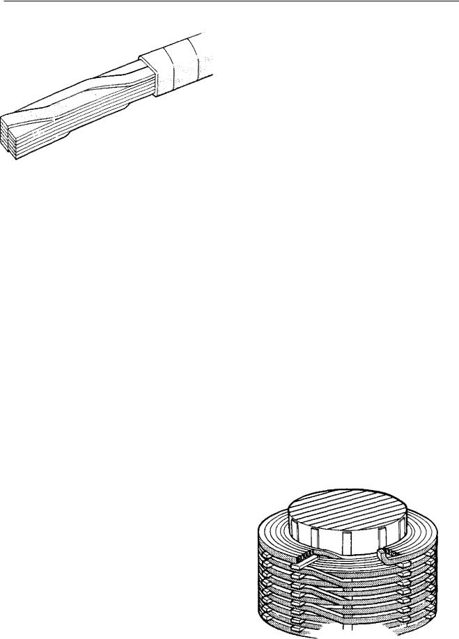
1.4.6 Continuously-transposed strip
Even with an arrangement of transpositions of the type described above and using many subconductors, eddy currents in very high current windings cannot be limited in magnitude to, say, 25% of the resistive losses as suggested in Section 1.3.4 of this chapter. In addition, transpositions of the type described above take up a significant amount of space within the winding. As a result, in the early 1950s, manufacturers introduced a type of continuously-transposed conductor. This enables a far greater number of transpositions to be carried out. In fact, as the name suggests, these occur almost continuously in the conductor itself before it is formed into the winding. Although the 'continuous' transpositions result in some loss of space within the conductor group, this amounts to less space within the winding than that required for conventional transpositions, so that there is a net improvement in space factor as well as improved uniformity of ampereconductor distribution. Figure 3.17 shows how the continuously-transposed conductor is made up. It has an odd number of strands flat formation insulated from each other by enamel only and these are in two stacks side by side axially on the erected winding. Transpositions are effected by the top strip of one stack moving over to the adjacent stack as the bottom strip moves over in the opposite direction. The conductor is moved sideways approximately every 50 mm along its length. In addition to the enamel covering on the individual strands, there is a single vertical paper separator between the stacks and the complete conductor is wrapped overall with at least two helical layers of paper in the same manner as a rectangular section conductor. Manufacture of the continuously-
208
General design and construction
FIG. 3.17 Continuously transposed conductor
transposed conductor involves considerable mechanical manipulation of the strands in order to form the transpositions and was made possible by the development of enamels which are sufficiently tough and resilient to withstand this.
The introduction of continuously-transposed strip has been beneficial to the design of large transformers, which must be capable of carrying large currents, but its use is not without some disadvantages of which the following are most significant:
•A stack which might be up to, say, twelve strands high, wrapped overall with paper, tends to behave something like a cart spring in that it becomes very difficult to wind round a cylindrical former. This problem can be limited by the use of such strip only for large diameter windings. It is usual to restrict its use to windings which have a minimum radius of thirty times the radial depth of the covered conductor.
•When the covered conductor, which will of necessity have significant depth in the radial dimension, is bent into a circle, the paper covering has a tendency to wrinkle. This feature has been termed 'bagging'. The bagging, or bulging, paper covering can restrict cooling ducts. This problem can be controlled by restricting the bending radius, as described above, and also by the use of an outer layer of paper covering which has a degree of 'stretch' which will contain the bagging. Also an allowance can be made by slightly increasing the size of the ducts.
•Because of the large number of strands, joints in continuously-transposed strip become very cumbersome.
•A high degree of quality control of the manufacture is necessary to ensure that defects in the enamel insulation of the individual strands or metallic particle inclusions do not cause strand-to-strand faults.
1.4.7 High voltage windings
Mention has already been made of the fact that the high voltage (I-1V) winding might have ten times as many turns as the low voltage (LV) winding, although the conductor size is considerably less. It is desirable that both windings should be as nearly as possible the same axial length and, assuming the LV winding occupied a single layer wound in a simple helix, the HV winding might require ten such layers. A multilayer helical winding of this type would be somewhat lacking in mechanical strength, however, as well as tending to have a high voltage between winding layers. (In a ten layer winding, this would be one-tenth of the line voltage.) [-IV windings are therefore usually wound as 'disc windings'. In a disc winding, the turns are wound radially outwards one on top of the other starting at the surface of the former. If a pair of discs are wound in this way both 'finishes' appear at the outer surface of the respective discs and the crossover between discs takes place at the inside of the discs. A series of discpairs can be wound in this way and then connected together at their ends to form a complete winding. Such an arrangement requires a large number of joints between sections and so has been largely superseded by the 'continuous disc winding'. This has the same configuration when completed as a sectional disc winding but is wound in such a way as to avoid the need for it to be made in separate disc-pairs. When the 'finish' of a disc appears at the outside radius, it is taken down to the mandrel surface using a tapered curved former. From the surface of the mandrel, a disc is then built up by winding radially as previously. When the complete disc has been formed, the tension is taken off the winding conductor, the taper former removed and the turns laid out loosely over the surface of the mandrel. These turns are then reassembled in the reverse order so that the 'start' is the crossover from the adjacent disc and the 'finish' is in the centre at the mandrel surface. The next disc can then be built upwards in the normal way. A section of continuous disc winding is shown in Fig 3.18.
FIG. 3.18 Arrangement of continuous disc winding
209
Transformers |
Chapter 3 |
|
|
The HV winding requires space for cooling-oil flow in the same way as described for the LV winding. This is provided using dovetail strips against the inner face of the discs and radial spacers interlocking with these. Radial cooling ducts may be formed either between disc pairs or between individual discs.
1.4.8 Tapping windings
Up to now, it has been assumed that power transformers have simply a primary and secondary winding. However, all power station transformers have some form of tapping arrangement to allow both for variations of the applied voltage and for their own internal regulation. The range of these tappings goes from -±5 07o variation, adjustable only off-circuit on the smallest transformers, to + ion, or more, on the larger transformers, selectable by means of on-load tapchangers. More will be said later about the subject of tappings and tapchangers. However, it is convenient at this stage to describe the tap windings themselves.
In power station transformers the tappings are invariably connected in the HV winding. The reasons for this are twofold. First, it is convenient to assume that the purpose of the tappings is to compensate for variations in the applied voltage which, for all transformers except the generator transformer, will be to the HV winding. (The generator transformer is a special case and will be discussed more fully in Section 2 of this chapter.) As the applied voltage increases, more tapping winding turns are added to the 1-1V winding by the tapchanger so that the volts/turn remain constant, as does the LV winding output . voltage. From the transformer design point of view, the important aspect of this is that, since the volts/turn remain constant, so does the flux density. Hence the design flux density can be set at a reasonably high economic level without the danger of the transformer being driven into saturation due to supply voltage excursions.
The second reason for locating tappings on the HV side is that, since this winding carries the smaller current, then the physical size of tapping leads is greatly reduced and the tapehanger itself carries less current.
Since the tappings are part of the HV winding, frequently these can be arranged simply by bringing out the tapping leads at the appropriate point of the winding. This must, of course, coincide with the outer turn of a disc, but this can usually be arranged without undue difficulty.
In the largest transformers, the tappings have to be accommodated in a separate tapping winding, but more will be said about this in Section 2 of this chapter.
1.4.9 Disposition of windings
Mention has already been made of the fact that the LV winding is placed next to the core because it has the lower insulation level. It is now necessary to look in further detail at the subject of insulation and in-
sulation levels and to examine the effects of these on the disposition of the windings.
Transformer windings may either be fully insulated or they can have graded insulation. In a fully insulated winding, the entire winding is insulated to the same level, dictated by the voltage to which the entire winding is to be raised on test.
Graded insulation allows a more economical approach to be made to the design of the insulation structure of a very high voltage winding. With this system, recognition is made of the fact that such windings will be star-connected and that the star point will be solidly earthed. The insulation of the earthy end of the winding thus need only be designed for a very nominal level.
BS171 requires that all windings up 10 66 kV working level should he fully insulated. Above this, which in the UK means 132, 275 and 400 kV, graded insulation is used. Since in UK power station systems there is no voltage class between 23.5 kV (which is treated as a 33 kV system) and 132 kV, then the former is the highest class of power station transformer winding to be fully insulated.
Power station transformers therefore either have both LV and 1-1V fully insulated or the LV fully insulated and the HV insulation graded. There are no transformers at power stations (unlike on the grid system) for which both windings can be graded.
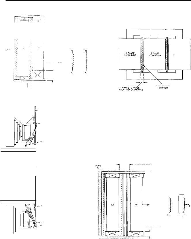
Figure 3.19 (a) shows the arrangement of a transformer in which both windings are fully insulated. This might be a unit transformer, 23.5/11 kV and perhaps around 40-50 MVA. The LV winding must withstand an applied voltage test which will raise the entire winding to 38 kV above earth. The winding insulation must therefore withstand this voltage between all parts and earthed metalwork, including the core. Along the length of the winding this test voltage appears across the dovetail strips plus the thickness of the SRBP tube. At the ends, these strips and the tube are subjected to surface creepage stress, so that the end-insulation distance to the top and bottom yokes must be somewhat greater.
The 23.5 kV HV winding is tested at 70 kV above earth. The radial separation between LV and HV must be large enough to withstand this with, say, a single pressboard wrap with spacing strips inside and outside (Fig 3.19). The end insulation will be subjected to creepage stress and so the distance to the yoke must be somewhat greater than the HV/LV distance. Between the transformer limbs, the HV windings of adjacent phases come into close proximity.
To withstand the 70 kV test voltage between phases, it is necessary to have a clearance similar to that between 1-1V/LV windings with, say, a single pressboard barrier in the middle of this distance, as shown in Fig 3.19 (b).
The LV winding leads are taken out at the top and bottom of the leg, which means that they must of necessity pass close to the core framework. Since they are
210
General design and construction
END INSULATION
r X3 NV LV DISTANCEI
tr
|
|
.4 .1 SULATION |
|
AI 3: ;;;.3' |
sec!Ien inroug hi one pease sr a |
||
• I |
aleo transformer showng |
||
iocs 0 |
, or ^ham ,sulation |
||
|
|
|
L'NE CONNECTION TO |
|
|
|
TERMINAL •N COPPER BAR |
|
|
|
WINDING CONDUCTORS |
|
|
|
|
|
|
|
BRAZED TO COPPER BAR |
WINDING END
CONNECTION
I
RISING
CONNECTION TO
NEUTRAL TERMINAL
CLEAT OF INSULATION
MATERIAL
NEUTRAL STAR BAR
LrrPical artangernen1 ol LV winding ends
A PHASE |
|
B PHASE |
Hy WINDING |
|
NV WINDING |
|
PRESSBOARO |
|
PHASE TO PHASE |
BARRIER |
|
INSULATION CLEARANCE |
|
|
Wi Elevaturin of lully nsulated 3p Vase |
|
|
transformer showing Inlerphase |
|
|
barrier |
|
|
|
HV LV INSULATION |
CORE |
LV
a 2
END leiJSLLATrON
CPHASE
-.3 NINCING
HV
A. thli
10.1 Section or transformer with NV winding having graded insulation
FIG. 3.19 Arrangements of windings and leads for fully insulated and graded insulation
211
Transformers |
Chapter 3 |
|
|
at relatively low voltage, it is probable that the necessary clearance can be obtained by bending these away from the core as close to the winding end as possible and by suitably shaping the core frame (Fig 3.19 (c)).
The [-IV winding leads also emerge from the top and bottom of the leg but these are taken on the opposite side of the coils from the LV leads. Being at a greater radial distance from the core frame than those of the LV winding, as well as having the relatively modest test voltage of 70 kV, these require little more insulation than those of the LV winding.
It is usually convenient to group the tapping sections in the centre of the HV windings. This means that when all the taps are not in circuit, any effective 'gap' in the winding is at the centre, so that the winding remains electromagnetically balanced. More will be said about this aspect below. The tapping leads are thus taken from the face of the HV winding, usually on the same side of the transformer as the LV leads.
Figure 3.19 (d) shows the arrangement of a transformer in which the LV winding is fully insulated and the FIV winding has graded insulation. This could be a station transformer, say, 132/11 kV, possibly 60 MVA. If this transformer had a tertiary winding, this too would probably be at 11 kV and would be placed nearest to the core. The test levels would be the same as for the II kV LV winding of the unit transformer and so the insulation arrangement would be similar to that described above. The 11 kV LV winding would be placed over the tertiary and the tertiary - to- LV gap would require radial and end insulation of a design si milar to that between tertiary and core. The 132 kV EIV winding is placed outside the LV winding and it is here that advantage is taken of the graded insulation.
For 132 kV class graded insulation, the applied voltage test is only 45 kV above earth, although when the overpotential test is carried out 230 kV is induced between the line terminal and earth. Consequently the neutral end needs insulating only to a level similar to that of the LV winding. However, the line end must be insulated for a very much higher voltage. It is logical, therefore, to locate the line end as far as possible from the core and for this reason it is arranged to emerge from a point halfway up the leg. The HV thus has two half-windings in parallel, with the neutrals at the top and bottom and the line ends brought together at the centre. If, with such an arrangement, the 1-IV taps are at the starred neutral end of the winding, the neutral point can thus be conveniently made within the tapchanger and the voltage for which the tapchanger must be insulated is as low as possible. Unfortunately, it is not possible to locate these tapping coils physically in the body of the HV winding since, being at the neutral end, when these were not in circuit there would be a large difference in length between the HV and LV windings. This would greatly increase leakage flux, stray losses and variation of impedance with tap position as well as creating large unbalanced forces on short circuit. It is therefore necessary to place the taps
in a separate winding located outside the HV winding.
This winding is shorter than the HV and LV windings and split into upper and lower halves, with an unwound area in the middle through which the HV line lead can emerge.
The centre of the HV winding must be insulated from the LV winding by an amount capable of withstanding the full HV overpotential test voltage. This requires a radial distance somewhat greater than that in the 23.5/11 kV transformer and the distance is taken up by a series of pressboard wraps interspersed by strips to allow oil circulation and penetration. Alternatively, it is possible that the innermost wrap could be replaced by a SRBP tube which would then provide the base on which to wind the HV winding.
The voltage appearing on test between the line end of the HV winding and the neutral-end taps is similar to that between HV and LV winding so it is necessary to place a similar series of wraps between the HV and tapping windings. These wraps must be broken to allow the central HV line lead to emerge; an arrangement of petalling or formed collars is normally used to allow this to take place without reducing the insulation strength (Fig 3.20).
1.4.10 Impulse strength
The previous section examined the disposition of windings as determined by the need to meet the power frequency tests which are applied to the windings. Nowadays it is the practice to apply an impulse test to power station transformers, as well as the dielectric tests at 50 Hz. Impulse testing arose from the need to si mulate the effect on the transformer of steep-fronted waves of the kind resulting from lightning strikes on the connecting transmission lines: these were of much greater voltage than the power frequency tests but also of very much shorter duration. The standard impulse wave defined in BS171 and specified by the CEGB for power station transformers has a wavefront time of 1.2 /Ls and a time to decay to half peak of 50 As (these times will be more fully defined in Section 1.7.6 of this chapter which deals with impulse testing of transformers). When struck by such a steep wavefront, a transformer winding does not behave as an electromagnetic impedance, as it would to power frequency voltages, but as a string of capacitors. Each turn has a capacitance to the succeeding turn C s and a capacitance to earth C g (Fig 3.21 (a)). It is a fairly simple matter to show that when a high voltage is applied to such a string, the distribution of this voltage is given by a curve of the type shown in Fig 3.21 (b) and the initial slope of the curve, which represents the voltage gradient at the point of application, is proportional to the ratio C g /C s . In a winding in which no special measures had been taken to reduce this voltage gradient, this would be many times that which would appear under power, frequency conditions. If additional insulation were• placed between the winding turns, this
212