

reading / British practice / Vol D - 1990 (ocr) ELECTRICAL SYSTEM & EQUIPMENT
.pdfSpecial design features
Flo. 3.69 Arrangement of Dinomig generator neutral earthing transformer (Balfour-Beatty Power Construction Ltd)
273

Transformers |
Chapter 3 |
|
|
( h)
3.70Typical forms of construction of metallic resistors
(a)Neutral earthing resistor having low inductive elements (GEC Industrial Controls)
(b} Neutral earthing resistor having non-inductive elements (Air Industrial Developments Ltd)
274
Special design features
GENERATOR |
GENERATOR |
|
MAIN |
||
TRANSFORMER |
GENErIATOR |
||||
|
CIRCUIT-BREAKER |
|
|
|
|
|
|
|
|
|
|
GENERATOR
NEUTRAL
EARTHING
TRANSFORMER
_ |
|
L |
|
|
|
UNIT |
"z"-- |
||
|
||||
|
|
|
||
|
|
TRANSFORMER |
BUS-BAR SYSTEM |
|
EARTHING MODULE
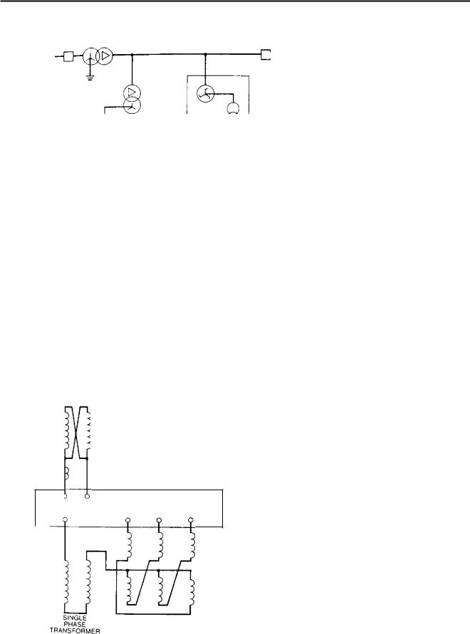
FTC, 3.71 Arrangement of 23.5 kV system busbars for a unit having a generator circuit-breaker
the main generator connections adjacent to the unit transformer, so that the interstar 'transformer' can be located outdoors alongside the generator and unit transformers and can thus be oil-filled. The 33/0.5 kV neutral earthing transformer can be installed in the same tank as the interstar transformer to provide a 23.5 kV system earthing 'module' shown diagramma-
tically in Fig 3.72.
The rating of the 33/0.5 kV portion of this module must be the same as that used for connection to the generator neutral. The interstar windings must be capable of carrying the unrestricted current that would flow with an earth fault on the 23.5 kV system, with the generator circuit-breaker open and the neutral earthing transformer shorted out (see Chapter 11). For
PPOTECTION
CT
INTERCONNECTED
STAR 'TRANSFORMER'
FIG. 3.72 Arrangement of 23.5 kV system earthing module
the system parameters appropriate to a 660 MW unit, this has been calculated as 550 A. It is assumed to persist for a time of 3 s which allows for the operation of back-up protection to clear the fault.
2.5.6 Harmonic suppressors
Sometimes an auxiliary system is required to operate for a long period with two earths connected to it. For example, a diesel generator providing emergency supplies when all other AC supplies have been lost must have a neutral earth connection when running in this condition. However, the same generator is required to run in parallel with the normal auxiliary system when normal supplies are being restored and also for test running purposes. In this situation its neutral earth connection will be in parallel with the auxiliary system earth connection. Although the return to normal supplies operation might involve no more than a brief period of paralleling, the test running condition might well be for a much longer period.
A system with two earth connections provides a path for circulation of third harmonic currents (see also Section 2.2.2 of this chapter) and these can produce unacceptable additional heating in generators, transformers and, in particular, earthing resistors. Where earthing resistors are of the electrolyte-filled variety, probably short time rated, this third-harmonic heating can be a severe embarrassment.
One possible solution is to utilise a switched neutral connection interlocked to ensure that only one connection is made at any one time. However, the control of this can be complicated and a simpler solution is to install a third-harmonic suppressor. This is an iron-cored inductor which is connected in series with one of the neutral/earth connections, usually the one which is not normally connected to the auxiliary system. Its design flux density is such that it is totally saturated at 50 Hz, thus having a low impedance at normal supply frequency, whereas at 150 Hz it operates below the knee point and, being unsatu-
275

Transformers |
Chapter 3 |
|
|
rated, has a high impedance, effectively equal to the magnetising reactance.
Practical values are less than 2 2 for an 11 kV device with an applied voltage equal to 10% of generator phase voltage at 50 Hz, and greater than 150 Si with this same voltage applied at 150 Hz. It must be rated for the continuous third-harmonic current produced by the expected level of third-harmonic voltage when applied to the combined impedance of the device and any neutral earthing resistor. In addition, it must be capable of carrying the fault current resulting from an earth fault on the associated system. For an 11 kV system, as provided for station or unit supplies associated with a 660 MW generator, this will be either 1000 A for 30 s, if limited by the system neutral earthing resistor, or 10 000 A for 3 s should this earthing resistor have been short-circuited.
The above currents determine the thermal rating of the harmonic suppressor. Should a system earth fault occur, coincident with a short-circuit of the neutral earthing resistor, the first-loop peak of the fault current will be limited only by the fully-saturated impedance of the harmonic suppressor and any impedance of the supply. The latter, being designed to the limits of the fault capability of the auxiliary switchgear, for example, 750 MVA at 11 kV, will be very low indeed. The fully-saturated impedance of the harmonic suppressor is that measured with an air-core alone and, for an 11 kV device designed to meet the requirements listed above, can be as low as 0.15 it resulting in a first-loop peak fault current of the order of 50 000 A. Such a fault current imposes a very high mechanical load on the suppressor and it is normal practice to prove the withstand capability by carrying out a type test on any new design at this level.
Because the suppressor has a high impedance to high frequencies, as represented by any voltage transients which might occur on the system, it is normal practice to connect a surge diverter across its terminals to provide a safe shunt path for these.
Figure 3.73 shows the typical arrangement of a harmonic suppressor as installed in the neutral earth connection of an 11 kV gas-turbine generator associated with a 660 MW unit.
2.6 Series reactors
2.6.1 General design features
Series reactors are sometimes referred to as current li miting reactors and, as the name suggests, are used for the purpose of limiting fault currents or restricting the fault levels of power station auxiliary systems. The reason for limiting fault levels is to ensure that the system will remain within the fault capability of the power station switchgear and since this has been developed to achieve the comparatively high levels of 750 MVA for 11 kV switchgear and 250 MVA for
|
|
|
|
|
|
|
|
|
|
|
|
|
|
|
|
|
|
CONSERVATOR |
|||
|
|
|
|
|
|
|
|
|
|
|
|
|
|
|
|
|
SURGE |
||||
|
|
|
|
|
|
DIVERTER |
|
|
||
|
|
|
|
|
|
|
|
|
|
|
iikv BUSHING |
|
|
|
|
|
|
|
|
||
|
|
|
" |
|
|
CABLE BOX |
||||
|
|
|
|
|
|
|
|
|
|
|
|
|
|
|
|
|
|
|
|
|
|
|
|
|
|
|
|
|
|
|
|
|
HARMONIC |
|
|
|
|
|
|
|
|
||
SUPPRESSOR |
|
|
|
|
|
|
|
|
|
|
|
|
|
|
|
|
|
|
|||
|
|
|
|
|
Th |
|||||
ALTERNATIVE |
|
|||||||||
|
|
|
|
|
||||||
POSITION |
|
|
|
|
|
|
|
|
|
|
FOR CABLE BOX |
|
|
|
|
|
|
|
|
|
|
CONCRETE
PLINTH
BUSHING
RESISTER SIDE |
|
|
|
GENERATOR SIDE |
CABLE BOX
Fic. 3.73 Arrangement of 11 kV harmonic suppressor
3.3 kV, the need for such current limiting reactors is rare. Their use on power station auxiliary systems is, therefore, the exception rather than the rule.
There are four basic types of current limiting reactor. These are:
•Cast-in-concrete air-cored.
•Oil-immersed gapped iron-cored.
•Oil-immersed magnetically-shielded coreless.
•Oil-immersed electromagnetically shielded coreless.
Ideally, current limiting reactors should have no iron circuit because all iron circuits exhibit a non-linear saturating-type characteristic, so that, under the very overcurrent conditions which the reactor is required to protect against, there is a tendency for the reactance to be reduced. Hence, the prevalence of coreless
reactors in this list.
The cast- in - concrete variety is therefore aimed at eliminating iron entirely and consists of a series of
276
Special design features
concrete posts supporting a helical copper conductor arrangement. The problems with these reactors 'result from the fact that they present extremely specialised manufacturing requirements, albeit that they are technically fairly crude. They tend to be sold in such small quantities that it is rarely worthwhile for a manufacturer to maintain the expertise. The major problem is to cast the concrete posts with a sufficiently consistent quality that they can be guaranteed crack-free, particularly since they are arranged in a circle of six, eight, or more, all of which must be made without defects to achieve an acceptable reactor.
As a result of the above problems it is likely that enquiries for cast-in-concrete inductors by most electrical plant manufacturers will be rejected.
Oil-filled reactors whether with or without an iron core have a number of features in common with transformers, hence most transformer manufacturers are able to design and build them.
Reactors with gapped iron-cores are most like transformers in their construction. In a three-phase reactor, a core of superficially similar appearance to a normal transformer core carries one winding on each limb, similar to a transformer winding. The core differs from a transformer core in that 'gaps' are inserted into the axial length of the wound limbs by the insertion of distance pieces made from non-magnetic material — usually pressboard. These normally make up no more than about I% of the iron path - length but have the effect of reducing the 'normal' flux density of the device to a level such that, even at fault currents of ten or twelve times normal full load current, the core is substantially unsaturated and the reactance is no more than 5-10% less than the value at normal full-load current. Such a device is shown diagrammatically in Fig 3.74.
Like transformers, reactors are subjected to large electromagnetic forces under fault conditions. Since each limb has only one winding, there can be no significant axial unbalance such as can be experienced in a transformer, so there will be no major end forces on winding supports. There remains an axial compressive force and an outward bursting force on the coils. The latter is resisted by the tensile strength of the copper which is usually well able to meet this but the winding must be adequately braced to prevent any tendency for it to unwind. Since reactor windings normally have fewer turns than transformer outer (HV) windings this aspect often requires more careful consideration than for a transformer (see Section 1.4.12 of this chapter).
The axial compressive force can, after repeated overcurrent applications, result in a permanent compression of the winding insulation with the result that windings can become loose. This must be prevented by the application of sufficient axial pressure during works processing to ensure that all possible
up at that time.
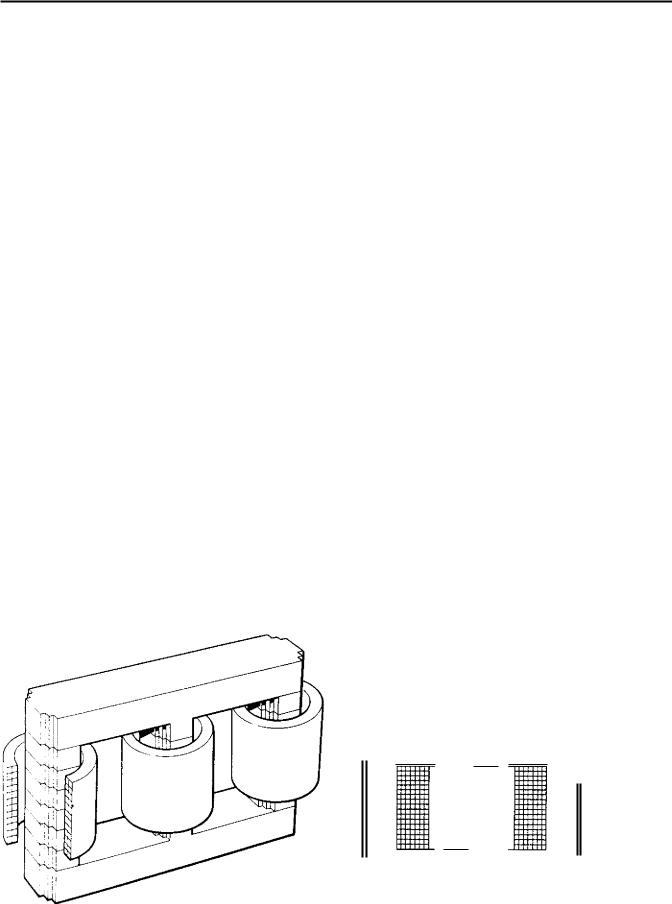
In a magnetically-shielded coreless reactor, the magnetic shield is arranged to surround the coils in much the same way as the yokes of a conventional transformer core. The shield provides a return path for the coil flux thus preventing this from entering the tank, which would result in large losses and tank heating. The larger the cross-section of the shield the greater is the quantity of iron required, the larger is the tank and oil quantity, and the more costly the reactor. If the shield cross-section is reduced, the flux density under normal rated conditions increases and the tendency to saturate under short-circuit currents is greater, thus bringing about a greater impedance reduction. CEGB practice is to specify that the impedance under short-circuit conditions shall not be less than 90% of the impedance at normal rated current.
In many respects the
reactor appears the most attractive in that it offers the advantage of constant impedance. In practice, this benefit is usually reflected in the cost. The arrangement of the shield for a single-phase reactor is shown in Fig 3.75. The shield, which may be of copper or
FLUXES
ADD
FLUXES
IJ CANCEL
SHIELD OF CONDUCTING MATERIAL
Flu. 3.74 Gapped iron-core reactor |
Fic. 3.75 Electromagnetically-shielded reactor |
277
Transformers |
Chapter 3 |
|
|
aluminium, provides a path for currents which effectively eliminate the return flux at all points outside the shield. The flow of shield current does, of course, absorb power which appears as heating in the shield. In addition to the balancing effect of the shield currents on flux outside the shield, there is some reduction of the flux within the coil, hence there is a reduction in its reactance. It can be show n, however, that this is independent of the current within the coil and is determined only by the inductance of the coil and the mutual inductance between coil and shield. As in the case of the magnetically-shielded reactor, therefore, there is a need to strike an economic balance between physical size, as determined by the size of the shield, and the unwanted reduction of reactance produced by placing the shield too close to the reactor coil. In practice the effective reactance of the coil and shield combination is made about 90 07o of the coil reactance alone.
2.6.2 Testing of series reactors
Testing of all reactors can present problems to the manufacturer which are not encountered in the testing of transformers. To a certain extent this results from the fact that they are made in very much smaller quantities than transformers and so manufacturers do not equip themselves suitably to deal with them.
Series reactors create two difficulties; one is concerned with proving the performance under short-circuit, the other with proving the adequacy of the interturn insulation.
Proving performance under short-circuit not only involves demonstrating that the reactor will withstand the fault currents which are very likely to be a similar magnitude to those in transformers but, for a magnetically-shielded or gapped-cored reactor, also establishing the reactance reduction which occurs under short-circuit conditions.
It is rarely possible to measure the impedance at the full short-circuit level, so that the usual approach is to measure impedance at 50%, 75% and 100% of rated current. For three-phase reactors, this is normally obtained from voltage and current measurements taken with the windings connected in star. A curve plotted from these values can then be extrapolated to the short-circuit level. Since this will involve considerable extrapolation (although the iron part of the circuit should operate below the knee point of the magnetising curve — even at the short-circuit current) it is usual, as a type test, to make an impedance measurement on one coil fully removed from the shield. This establishes an absolute minimum impedance which may be used as an asymptote for the extrapolated impedance curve.
The normal method of proving the interturn insulation of a transformer is to carry out an induced overvoltage test during which a voltage of twice the normal interturn voltage is developed. Such a test would not be very effective for a series reactor since the 'normal' voltage between turns will be very small
and even increasing this to twice its normal value is unlikely to give rise to any particularly searching stress. The usual solution is to apply an impulse test to each line terminal in turn which, as explained in Section 1.4.10 of this chapter, will generate a more significant voltage between turns. The test level is usually the same as would be applied to the same voltage class of transformer. CEGB practice is to apply two full-wave shots preceded and followed by a reduced (between 50 07o and 70%) full-wave application. Other tests are more straightforward and similar to the tests which would be carried out on a transformer, so that a full test series might consist of:
•Winding resistance.
•Oil samples.
•Loss measurement.
•I mpedance measurement.
•Zero phase-sequence impedance.
•Noise level.
•Applied voltage test, including measurement of partial discharge.
•I mpulse test.
•Oil samples (repeat).
•Insulation resistance.
•Magnetic circuit and associated insulation appliedvoltage test.
2.7 Instrument transformers
2.7.1 Voltage transformers
As stated at the opening of this chapter, a transformer does not achieve a perfect transformation of voltage and current. The user of a power transformer must accept the facts of regulation and leakage reactance and this he is normally able to do. For instrument transformers, however, these imperfections are less acceptable and the design of the transformer must aim to reduce them to the minimum. Figure 3.76 shows the phasor diagram for a transformer carrying a lagging power factor load 12.11 is the balancing primary current (the diagram assumes unity turns ratio). When added to the magnetising current I c,, this current produces a total primary current I , The secondary induced EMF E2 is modified by reactance and resistance voltage drops to give a terminal voltage lh and, similarly, applied voltage V I results in primary induced EMF E1 . A fuller development of this diagram can be found in any standard electrical engineering textbook. From the diagram, it can be seen that primary and secondary voltages are not exactly in proportion to the turns ratio, neither are they precisely in opposition to each other. The differences are known as the and respectively.
278

Special design features
En, 3.76 Phasor diagram for transformer with lagging power-factor load
Voltage transformer accuracies require the designer to restrict these errors to known small quantities. This is possible provided that the transformer is operated vothin strict limits.
The most significant of these limits is the load applied to the voltage transformer which is expressed in VA and known as the burden, but it is also necessary to ascertain that applied voltage, frequency and power factor are within the bands prescribed by the transformer designer.
The limits on phase-angle and ratio error are usually defined by specification and for voltage transformers used within the CEGB BS3941 1975 [17j is the applicable standard.
BS3941 classifies voltage transformers in accordance with their percentage voltage ratio error and with the use to which they are to be put.
Voltage transformers used for measurement purposes ma ■. provide a signal to tariff metering equipment or they may be used to control equipment associated with a generator AVR or a transformer onload tapchanger. Such signals are required to have
high accuracy and five classes of measuring voltage transformer are defined having voltage ratio errors
±0,1, ±0.2, +0.5, +1.0 and +3.0%, the individual classes being identified by the use of a number equal to the percentage voltage ratio error. Thus accuracy class 0.1 defines a voltage transformer having ratio error within +0.1% of nominal.
Voltage transformers used in protection schemes do not require such a high degree of accuracy. Usually these are feeding equipment which simply requires to
know whether a supply is energised or not, for example, no-volt relays, although occasionally wattmetric equipment might be involved such as low forward power, or reverse power relays (see Chapter 11). Protective voltage transformers having errors of +3.0 and ±6.0% are defined in BS3941. These are identified in a similar manner to measuring voltage transformers but the designation is given in addition to a suffix letter P. Hence class 3P defines a protective voltage transformer having voltage ratio error +3.0%.
The voltage error limits given above for measuring voltage transformers apply over the range 80ro to 120% of rated voltage with burdens of between 25 07o and 100% rated burden, at a power factor of 0.8 lagging and at rated frequency.
Many forms of protection require a voltage transformer capable of reproducing the primary phase-to- earth voltage. This is provided most conveniently using single-phase units connected between line and earth. This can, however, create problems for the voltage transformer designer, depending on the system earthing conditions. When there is a single-phase to earth fault on the system to which the transformer is connected, there is also an increase in the voltage to earth of the sound phases which thus imposes an overvoltage on the VTs associated with those phases. The transformers experience an increase in flux density in the core, with a resulting increase of magnetising current flowing in the primary winding. Both of these could produce overheating, unless the transformer is suitably designed.
The same effect would occur in a three-phase star connected transformer and, in addition, a residual flux would be produced by the unbalanced voltages. This flux cannot be contained within a normal three-phase three-limbed core, so such transformers must have three separate single-phase cores (making them virtually singlephase transformers) or incorporate extra return limbs, or employ a shell-type core construction as shown in Fig 3.77.
The magnitude lnd duration of the increased voltage depends on the method of system earthing and the
type of protection against earth faults. BS3941: 1975 therefore defines a rated voltage factor for all voltage
transformers which varies from 1.2 continuous for VTs connected between lines in any network to 1.9 for 8 h for VTs connected between line and earth in an isolated neutral system without automatic earth fault tripping. Note that the use of voltage factors even as high as 1.9 does not affect the insulation level requirement of a VT. Insulation level is based on system highest voltage which is related to the highest voltage that can occur between lines: this is normally greater than that occurring between line and earth,
2.7.2 Generator voltage transformers
The most important voltage transformers on a power station system are those connected to the generator
279

Transformers |
Chapter 3 |
|
|
FR:, 3.77 Shell-type core construction for a protection VT
busbars. These provide signals to the automatic voltage regulator (AVR), protection equipment, metering and synchronising equipment. As indicated in Section 1.6.9 of this chapter, they can also be used to initiate automatic control equipment, such as that associated with the generator transformer cooling.
Single-phase voltage transformers are used for the reasons discussed above, and also to make possible a totally phase-isolated system of connections to the generator terminals (see Chapter 4).
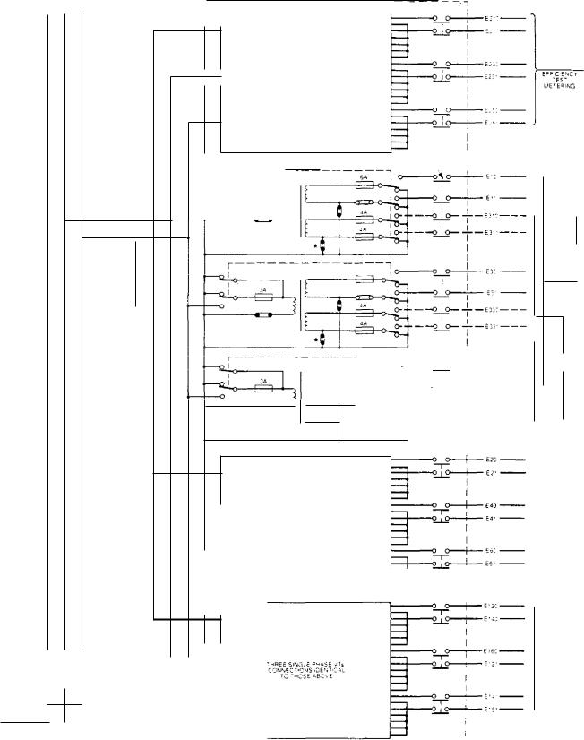
On a modern 660 MW generator, four sets of such VTs are used, and connected as shown in Fig 3.78. The generator voltage system is high-resistance earthed at the generator neutral (see Section 2.5.1 of this chapter and Chapter 11), so the CEGB specifies a rated voltage factor of 1.9 for five minutes. This apparently long duration was selected when high-resistance earthing of the generator neutral was first introduced, the stator earth fault trip was made an unloading trip, i.e., the generator circuit-breaker was not opened until after the turbine throttle valves had been closed to reduce the load to zero. Whilst the unloading trip is no longer used, the timescale has been retained for the purposes of standardisation and interchangeability.
For a generator voltage of 23.5 kV, the VTs have a primary rated voltage of 221./3 kV and a secondary rated voltage of 110/./3 V. This gives a rated transformation ratio of (22 000/V3)/(1 101.13) resulting in \.oltage ratio of 200 to 1, which is a simple round number. Reference to BS3941, Table 1 (Rated transformation ratios) shows that standard practice is to specify transformation ratios for single-phase VTs in this way, using secondary voltages of 110/V3 and primary voltages which are multiples of eleven, also
ided by ./3.
It will also be seen from Fig 3.78 that the transformers are provided with tertiary windings, which
can be connected in open-delta. The reason for this is now largely historical and originated with the objective of providing protection against neutral instability, also sometimes known as 'neutral inversion'. This can arise on the neutral of the generator voltage system when it is earthed only via the star point of the generator VTs and when the VT magnetising current, which is highly inductive, is of the same order of magnitude as the capacitive current to earth in the generator windings. A resonance is thus produced which can result in high voltages between phases and earth, resulting in breakdown of the generator neutral. The problem can be avoided by high-resistance earthing of the generator neutral, which is now standard practice for other reasons (Chapter 11), and by ensuring that the VT works at a sufficiently low flux density so that it is always on the linear part of the magnetising curve and there will be no chance of saturation. This is good VT design practice anyway, and is done to ensure that the magnetising current is low to minimise transformation errors. However, provision of a tertiary winding costs very little and, in order to allow standard interchangeable VTs to be used, one is provided on each. Provision of the connections to enable the tertiary windings of only one set of VTs to be connected in delta is, of course, all that is required from the external wiring and it is CEGB practice to install this only to the tariff-metering VTs as indicated in the diagram.
As mentioned above, it is desirable that all generator voltage transformers should be identical, so it is CEGB practice to specify that these should have a dual 50/150 VA rating with high accuracy (Class 0.2) at the 50 VA rating required for the supply of the AVR and metering equipment, and the lower accuracy (Class 1 and Class 3P) at the 150 VA rating appropriate to the protection duty.
The insulation system used for generator voltage transformers is cast-resin and, since the 1970s, HV, LV and tertiary windings have all been encapsulated. Solid insulation is used in preference to oil, since it avoids any material having a fire risk being in the vicinity of such high integrity plant as the main turbinegenerator. The advantages of cast-resin in preference to dry-type class C insulation are discussed in Section 2.4.2 of this chapter.
The group of four voltage transformers for each phase is protected by a 10 A fuse fitted at the point where the voltage transformer tee-off is made to the generator phase-isolated busbars. Phase isolation is maintained throughout the tee-off (see Chapter 4) and each voltage transformer is protected by an individual 3 A fuse at the point of further sub-division from the tee-off. These can be identified in Fig 3.76. The voltage transformer is housed within a 'drawer' or 'drum' so that it can be withdrawn and isolated from the generator voltage system whilst the latter remains energised. The act of withdrawal brings about automatic earthing of the primary line connection, on both sides of the 3 A fuse, and also earths all secondary connections.
280

Special design features
Fuses for secondary and tertiary windings must be mounted as close as possible to the winding terminals, since any wiring between winding terminal and fuse is unprotected. The impedance of the voltage transformer is such that the primary 3 A fuse does not provide protection against secondary or tertiary wiring faults. In addition to the need to ensure that the VTs themselves have the highest possible integrity, it is important that the likelihood of faults on any equipment connected in the vicinity of the generator busbars should be made as low as possible because of consequential damage that can be caused by such faults. Normally, a voltage transformer having resin-encapsulated windings will have an external, non-encapsulated, core having steel channel sections to apply clamping pressure. It is usually convenient to mount secondary and tertiary fuses, links and earth links within one of these channels. Such an arrangement is seen in Fig 3.79, which shows the completed installation for a 660 MV generator; the fuses and links, etc., are concealed behind the cover plate in the foreground.
2.7.3Current transformers
For all transformers discussed thus far, it is the case that events occurring in the secondary circuit are reflected in the primary, changed only by a factor dependent on the transformation ratio: a short-circuit of the secondary appears as a short-circuit to the primary supply, open-circuiting the secondary appears as an open-circuit to the primary supply. A current transformer is fundamentally different since no event occurring in the secondary circuit can in any way affect the current in the primary.
The purpose of this volume is to deal with practical aspects of power station plant and reference can be made to any standard textbook for most areas of electrical theory. It is however necessary to examine transformer theory as it is applied to current transformers M some detail in order to appreciate this fundamental difference and the significance of the various design features. The following few paragraphs will attempt to do this. The reader will find a more exhaustive treatment in 'Current Transformers, their transient and steady state performance' by Arthur Wright (18].
The phasor diagram of a current transformer is shown in Fig 3.80. The resistance and reactance drops in the transformer and the magnetising current play their part in determining the dispositions of the various phasors, as in the case of a voltage transformer, but their relative values and the significance of the various phasors are very much different.
Figure 3.81 represents the conventional equivalent circuit for a transformer for which the primary winding resistance and reactance are negligible. This is a valid assumption for a current transformer whose inclusion does not have any effect on the current flowing in the primary circuit. Other circuit values as indicated in the diagram are as follows:
LM Magnetising inductance
R2 Secondary resistance
R p Resistive component of core loss
L2 Secondary inductance
1 0 RMS value of exciting current
lp RMS value of resistive component of exciting current
I n„ RMS value of magnetising component of exciting current
Ni Number of turns on primary winding
N2 Number of turns on secondary winding
et EMF induced in primary winding
e2 EMF induced in secondary winding
ZB Burden
From the equivalent circuit, the exciting current of the transformer is dependent on both the impedance of the magnetising 'branch' and the EMF required to drive the secondary current through the total secondary circuit impedance. Because the secondary current of a current transformer may vary over a wide range, from zero under no-load conditions to very large values under primary system fault conditions, the exciting current also varies greatly. This represents a significant difference between current transformers and voltage transformers since the latter operates at almost constant excitation current under all normal conditions.
In a properly designed current transformer loaded with its correctly rated burden, the secondary EMF required to circulate secondary rated current will be low enough to ensure that the core does not approach saturation. Nevertheless, the exciting current will have a non-sinusoidal waveform. Since at any instant the total ampere-turns provided by primary and secondary windings must equate to those required to excite the core, then on the assumption that the primary current is sinusoidal, the secondary current must contain any harmonics. The degree of distortion of the secondary current waveform will, however, be less than that of the exciting current since the magnitude of the latter will be small in relation to the secondary current under all normal conditions.
Considering the phasor diagram of Fig 3.80, it can be seen that the error in the current transformation ratio is created by the exciting current. Once the exciting ampere-turns have been determined, therefore, the error can be obtained by comparing the exciting ampere-turns with the primary ampere-turns. However, if the exciting current is non-sinusoidal, it is difficult to express the error in precise terms since, although its RMS value can be calculated, it is difficult to assign a phase angle relative to the primary or secondary current. For this reason, it is the accepted practice to express errors in current and phase by assuming that the exciting current is sinusoidal
281
Transformers |
|
Chapter 3 |
|
|
|
7 |
GENERATOR VTs |
|
THREE SINGLE PHASE VTs |
E , K.C'ENC |
|
TES T |
||
CONNECT.GNS IDENTICAL |
kIETER ING |
|
TO THOSE BELOW |
||
|
OPERATED |
TF-IAUE T CUBICLE ATE SS TE • , |
S.NOLE |
|
sy4 |
INTERLOCK TWITCH |
|
|
|
--e |
- |
|
|
3A |
|
|
|
|
• 7.4 |
|
|
|
|
|
|
6.A
-rARIFIT METEANG
IN sTauMENTS
AND FUSE PAL
mONITORING
5A |
1 0 |
|
|
22H |
|
|
|
|
|
|
|
|
.0 110 |
E:' |
|
|
|
|
|
|
|||
4A |
|
|
|
|
I |
|
|
|
|
|
— --0 I 0— — E35.T. |
|
|||
|
|
|
|
|
|||
4A |
I |
|
|
|
|
|
|
|
|
|
— —0 I 0— — E |
— |
|||
|
047 |
- |
|
||||
|
|
|
I |
|
|
||
|
|
|
|
|
|
|
|
|
|
|
|
|
|
|
|
|
|
|
|
|
|
|
|
|
|
|
|
|
|
|
THREE S.NGLE EVADE VT5 |
|
AUTOMATIC |
|
|
|
|
|
|
|
VOLTAGE |
||
|
|
|
|
|
CONNECTIONS GENT CAL |
|
REGULATOR |
|
|
|
|
|
|
TO THOSE ABOVE |
|
CHANNEL A |
|
|
|
|
|
|
|
|
AND PROTECTION |
|
|
1.1..•■•■ |
|
|
|
|
|
|
|
|
|
|
|
|
||||
|
|
|
|
|
|
|
|
|
|
|
|
|
|
|
■■■•■ |
||
|
|
|
|
|
|
■■. |
||
|
|
•••■•■ |
|
|
|
|
|
|
|
|
|
|
|
|
|
||
|
|
|
|
|
|
|
||
■1■■••. |
|
|
|
AUTOMAT:C. |
|
||||
'MPH SIN3,Z . , 111SE |
|||||||||
|
VOLTAGE |
||||||||
|
|
|
|
CCNNECT.ONS .DENT.C ,, L |
|
||||
|
|
|
|
TO |
ABOVE |
|
REGULATOR |
||
|
|
|
|
|
CHANNEL e |
||||
|
|
|
|
|
|
||||
|
|
|
|
|
|
|
AND PROTECTION |
||
|
|
|
|
|
|
|
|
|
|
|
|
|
|
|
|
|
|
|
|
|
|
|
|
|
|
|
|
|
|
1
*EAP..I'EvC |
DELTA EL:PCEN:S.JSE 2 |
|
- |
FIG. 3.78 Generator VT connection arrangement
282