

reading / British practice / Vol D - 1990 (ocr) ELECTRICAL SYSTEM & EQUIPMENT
.pdfComponent parts of an IP2 system
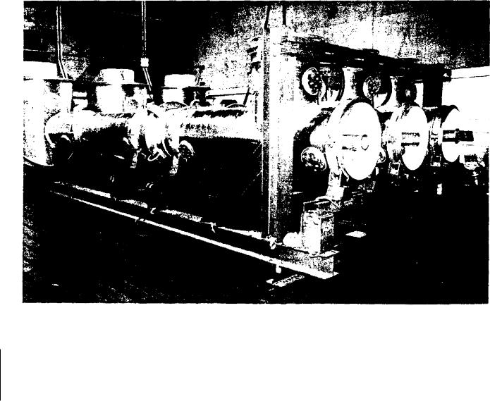
EIGHT TRANSFORMER DISC BUSHING
ACOUSTIC
ENCLOSURE
|
EXPANSION |
|
|
|
|
|
|
|
|
EXPANSION |
|||||
|
BELLOWS |
|
|
|
|
BELLOWS |
|
|
|
|
|
|
|||
ACCESS COVER_j- |
|
|
|
|
|
||
ACCESS COVER |
|
|
|
||||
|
|
|
|
|
|
|
|
|
|
|
|
|
|
|
|
|
|
|
|
|
|
|
|
|
|
|
|
|
|
TRANSFORMER |
|
|
|
|
BONDING STRAP |
' |
BUSHING |
||
|
|||||||
Fic. 4.23 Generator transformer connections
'stick-on' tapes available to record the maximum temperature attained at a spot. They have the obvious disadvantage that they can only be read after the system has been de-energised but they are a useful way of doing a temperature survey. Temperature-sensitive paints are also available which change colour at a set temperature. For both these methods, it is essential to ensure that, once the sensor has been 'triggered', it remains stable until an opportunity to check it is available. Thermocouples and contact thermometers also exist, but they are generally only of use on the star-bar because of the high voltages involved. An alternative method is an infra-red camera, which ob- N iously requires line-of-sight vision to the spot to be measured. Painting the surface of the joint can improve the efficiency of emission of infra-red. Since magnetic fields can influence an infra-red camera, caution must be exercised when using it.
Because of the difficulty of temperature measurement, indirect methods of monitoring can be considered. Checks of joint resistance, using a micro-ohm meter, can be made during plant shutdown, and all joints checked for obvious signs of discoloration due to high temperature.
If viewing ports are provided, both the infra-red camera and visual checks for discoloration are possible. Hot spots only occur at jointed areas; the general busbar temperature is not a problem, provided that the busbars have been correctly designed.
7.16 VT cubicles
Each phase may require up to five VTs arranged in isolated phase compartments. When isolating a VT, it is usual to break the primary side before the secondary side, so that isolating contacts compatible with the secondary voltage can be used. Each VT is separately protected by a primary fuse, typically 3 A, which discriminates with the 10 A fuse fitted at the tee-off, already described. The VT secondary wiring, suitably fused, is wired to a combined CT and VT secondary marshalling cubicle and then into its associated protection or instrumentation scheme. When the VT is isolated, before access can be gained to it, earths must be applied by the VT isolating mechanism to both sides of the 3 A fuse, and the primary and the secondary terminals of the transformer. To ensure that this procedure is followed,
interlocked.
7.17 Access platforms
Since the main connections route is complicated by proximity to other plant, some access covers are unavoidably located at awkward places; access platforms are therefore necessary to facilitate quick inspection of joints and connection of portable earthing equipment. Sufficient room must be available for an operator to manoeuvre voltage sensing probes, earth application
313
Generator main connections |
Chapter 4 |
|
|
poles, etc. Care must be taken to ensure that ladders and handrails do not bridge insulated joints electrically at plant interfaces and thus render them ineffective. Also, such structures in the vicinity of the connections are designed so that they are not heated b ■ stray magnetic fields during continuous operation of the plant.
The continuity of any current-conducting path in the steelwork should be interrupted by the inclusion of insulating pads, bushes and washers, etc. Attention should be given to the need to sectionalise or insulate cladding or screens.
7.18 Structural steelwork
Structural steelwork running parallel to main connections enclosures must be spaced at least 300 mm distant. Steelwork running at right angles to main connections enclosures must be spaced at least 150 mm distant. The supporting structure for the whole of the main connections, including the tee-off connections, is designed to give a rigid structure for the static and dynamic loads imposed with a typical safety factor of 1.5. Supports must be completely independent of the equipment to which the busbars are connected and separate from main building steelwork. They are floor-mounted and designed to prevent heating of the structure by magnetic leakage fields.
7.19 Neutral earthing equipment
This equipment has developed in the manner described in Section 11 of this chapter and, for a 660 MW generator, typically comprises a solid insulation (SNAW) 462 kVA cast-resin transformer with a suitably-sized load resistor and anticondensation heater mounted within a free-standing module, one per unit. The transformer is normally unenergised, so particular attention must be given to ensuring that the complete encapsulation performed under vacuum is free from voids, cracks and other defects, and accurate location of the winding is essential. The resistor is likely to be of the metallic type and have a value which limits the earth fault current to 10-15 A in each neutral. It will be air cooled, non-deteriorating, non-corrodible and fireproof, non-inductive and capable of carrying the earth fault current for five minutes without mechanical damage: the total resulting temperature rise should not exceed 200 ° C.
7.20 Site installation
Clearly it is advantageous to do as much factory fabrication as possible, subject to transportation limits. Equipment housings and sections including bends require more complicated fabrication techniques and are best done at the works, leaving the relatively easy welding of straight joints to be done on site. The sec-
tions are transported complete, i.e., they include conductor, enclosure, insulators and all fittings.
7.21 Quality assurance
Notwithstanding the quality checks required for each individual component, careful final assembly and welding of the busbar sections is most important. Welding must be in accordance with a specified standard, e.g., 13S3571 Part 1 for metal arc welding or BS3019 Part 1 for tungsten arc welding (both inert gas), and all welds must be clearly identified in the design, including their type, weld process, weld preparation, with samples of each weld type made available for examination. Welds can be grouped as electrical circuit welds or structural/ mechanical welds and detailed welding procedures are prepared. Testing of welds by radiography and dyepenetrant techniques is carried out on a percentage of all welds produced, with clear acceptance levels agreed before work starts.
8 Testing
This section covers tests for:
•Component parts of the main connections installation.
•Manufacture of a test piece to ensure adequate design.
•Testing on site.
•Type tests.
•Routine tests.
•Sample tests.
8.1 Tests on component parts
8.1.1 Insulators and bushings
At the time of writing, these components are made of an epoxy material. Type tests are carried out on samples of complete insulators representative of each type used in the installation; they will already have passed the specified Routine tests. Each insulator type needs a different jig in order to subject it to realistic testing. The necessary corrections for temperature, barometric pressure and humidity are applied. Typical type tests are:
• |
Lightning-impulse voltage withstand This is the |
|
standard 1.2/50 As impulse test with the test con- |
|
ditions given in BS3297 Part 1 1974 or BS223 1985 |
|
as appropriate, the test value being that for the |
|
highest system voltage of the installation. |
• |
Dry power frequency withstand To BS3297 at the |
|
appropriate test value for one minute. |
314

Testing
• |
Wet power frequency withstand |
To BS3297 at the |
|
|
|||
|
appropriate test value for one minute. |
||
• |
Partial discharge test |
Carried out in accordance |
|
|
|
||
|
BS4828, the partial discharge being measured |
||
|
in terms of apparent charge; the level should not |
||
|
e\ceed 50 pi,:acoulombs. |
|
|
• |
Cantilever mechanical owe-test |
This is applied to a |
|
|
|||
|
complete insulator secured by its normal means of |
||
|
ji \ jog, with the load applied at right angles to the |
||
|
asis of the insulator. This test would not be applied |
||
|
to a disc bushing. |
|
|
The following Routine tests should be carried out on all individual insulators and bushings:
• |
Visual examination. |
• |
Electrical routine test A 1-minute withstand test at |
|
the appropriate voltage. |
•Afechanical routine test A cantilever test at 70 07o of the failing load of the insulator in this mode.
In addition to these Type and Routine tests, the following Sample tests should be performed; the method of selection is discussed in BS3297 Part 1, 1974:
• |
Verification of dimensions |
This involves checking |
|
that the dimensions are in accordance with the re- |
|
|
levant drawings, with due regard for tolerances and |
|
|
other details which may affect interchangeability. |
|
• |
Temperature cycle sample test Several cycles of |
|
|
i mmersion in hot and cold water, the sample being |
|
|
held at each temperature for one hour to ensure |
|
|
(hat a uniform temperature has been attained. The |
|
|
difference in hot and cold temperatures should not |
|
|
be less than 70° C. This test would be followed by a |
|
|
routine electrical test to ensure that no degradation |
|
|
of the insulator has occurred. |
|
• |
Oscillatory-load sample test |
This simulates mechani- |
|
cal shocks onto the main connection installation |
|
|
caused by, for example, operation of a circuit- |
|
|
breaker. The number of oscillations selected is left |
|
|
to the judgement of the engineer specifying the |
|
|
installation (of the order of four million), but is |
|
|
not applicable to disc bushings. |
|
• |
Tension sample test Each sample insulator is |
|
|
subjected to 70 410 of its ultimate tensile failure load |
|
|
for one minute without failure to it or its fixings. |
|
|
It is not applicable to disc bushings. |
|
•Torsional sample test A torsional load is applied to each threaded insert or stud of an insulator or bushing to demonstrate that no permanent distortion
or loosening of fittings occurs. For thread sizes up to M12, a load of 50 Nm is used.
For this, the insulator is i mmersed in switchgear oil and a voltage of approxi-
mately 50°-1() of the specified puncture voltage applied across the unit. This voltage is then increased graduall ■, to 1.3 times the actual dry flashover voltage of the unit without causing puncture.
• Ultimate cantilever-load sample test Finally, a unit should be loaded up in the cantilever mode until failure occurs. For this sample test, failure should not occur below 80N of the failure load obtained from the Type testing.
8.1.2 Busbar material
Checks are made to ensure that the material is to specification and that different material types are clearly identified, so that the incorrect material or thickness cannot be inadvertently used in any part of the installation.
8.1.3 Transformers
The various VTs and CTs throughout the system require Type and Routine tests, as described in Chapter 3.
8.1.4 Loading resistors
The neutral earthing system loading-resistor must be tested in accordance with BS587: 1957, as follows:
Type testing
•High voltage.
•Ohmic value of resistor.
•Temperature rise.
Routine testing
•High voltage.
•Ohmic value of resistor.
8.1.5 Capacitors
Capacitors may be installed in the main connections for the reasons explained in Section 10 of this chapter. They should be tested in accordance with BSI650.
8.1.6 Switchgear and earthing switches
Testing requirements for switchgear are discussed in Chapter 5.
Type and routine testing of earthing switches is in accordance with BS5253, the test arrangement simulating the service condition as far as practical, i.e., the switches should be mounted in their service enclosures, together with a section of busbar. The short-circuit test is made on a three-phase group of switches, but all other tests may be performed single-phase.
Control and electrical interlocking circuits, if applicable, should be tested for correct operation.
315
Generator main connections |
Chapter 4 |
|
|
8.1.7 Compressed air system
All compressors, pipework, valves and ancillary apparatus are tested to appropriate standards, i.e., the pressure of their associated safety valves, with air receivers being pressure tested to one and a half times their safety valve operation pressure.
8.2 Tests on representative sections of IPB
It has been explained earlier that calculation of the forces that exist upon a main connections installation during short-circuit is very difficult and at the time of writing there is no reliable calculation method available. Any computational method later developed will require validation by testing. Consequently the CEGB's normal practice is to test the capability of a main connections design by subjecting it to the worst fault currents which might occur in service. There are limited facilities worldwide where tests of this kind can be carried out, and such testing is very expensive. It may be advantageous for the manufacturer to offer a main connections installation of higher current rating than is necessary simply in order to use a tested design, thereby making repeat tests unnecessary.
It is normal to offer two test pieces; a section of main and tee-off busbar, including the tee-off itself,
and the delta section. The former requires representation of all three phases and the earth bar whereas for the latter a 'go and return' section plus earth bar suffices. An example of a test piece comprising aluminium busbar in an aluminium enclosure representative of a unit transformer tee-off connection is shown in Fig 4.24.
Consideration should be given to incorporating additional equipment into the test piece, for example CT chambers, expansion joints, flexible connections, etc.
The following design aspects of the test piece should be considered. in addition to the selected test piece, it is advisable to add a short interface section where connections are made to the incoming unscreened section of the test station busbar. This reduces the end effects of non-representative connections on the test piece. The connection to the test station supply is by flexible connections, as used in normal service. The short-circuit is by means of a shorting bar of construction generally similar to part of the main connections installation. It is connected to the test piece by joints similar to a normal tee-off but strengthened, typically by welded webs, in order to withstand the high knife-switch forces in this area, those forces being higher than those in practice at a right-angle bend. In a single-phase-to-earth fault, connection to the test piece is in a section of earth bar returning to the test
FIG. 4.24 Test piece for generator main connections
316

Testing
station connections by unscreened conductor, this being representative of a normal earth bar arrangement in a pical design. Laminated flexible sections should be provided at each end of the screened conductor and the conductor held down in the manner proposed in the earth bar design. Bonding bars should be incorporated in the tot piece at the test supply end, though
[ b e |
short-circuit bar enclosure will provide the bonding |
|
b et ween |
individual phase enclosures at the remote |
|
|
||
cnd of the tes• piece.
It is recommended that the following measurements
are recorded:
• |
Input |
The applied current (and voltages) are re- |
|
corded on UV oscillographs. It is advisable to take |
|
|
additional current measurements using Rogowski- |
|
|
coil type current transducers in various parts of the |
|
|
test piece, these being particularly useful for dia- |
|
|
gnostic purposes should some failure occur. (If any |
|
|
CTs are fitted in the test piece, they should have |
|
|
their secondary windings shorted unless some mea- |
|
|
surement of their output is required.) |
|
• |
Force piezoelectric force transducers should be |
|
|
positioned to measure load on the earth bar. If a |
|
|
correlation is being made between the test results |
|
|
and predictions by calculation, as many transducers |
|
|
as possible should be applied to the earth bar to give |
|
|
greater confidence in the calculation method. |
|
• |
Voltage rise The voltage rise in various parts of |
|
|
the test piece should be measured relative to one |
|
|
point on the test piece. |
|
• |
Temperature Maximum-indicating temperature de- |
|
|
vices of the stick-on type should be liberally applied |
|
|
to the test piece in order to record the maximum |
|
|
temperature reached. These should be examined |
|
|
after the one-second test (see Section 7.15 of this |
|
chapter) to ensure that the final conductor temperature does not exceed specification. Clearly, initial temperature prior to short-circuit must be recorded to determine temperature rise. The thermal shortcircuit capacity of the main busbar is far in excess of the actual values due to the high continuous current and large conductor and enclosure crosssections. For the unit transformer tee-off, the temperature rise has less margin due to its relatively smaller cross-section.
8.3 Test levels
The fault conditions normally quoted in a specification are synthetic insofar as the actual fault currents that
flow on a given power station installation cannot be predicted precisely. The test values are therefore derived from real plant parameters, assuming that all
[he variables combine at their worst. The test philosophy is based on the presumption that any real fault vh ill be less severe than the test condition.
The values of fault conditions are the sum of the contributions from the generator side and the generator transformer side of the system. The design values should be applied throughout the system, including the associated earth bar system, to ensure a high integrity.
For a 660 MW installation, the test levels quoted would be as follows:
(a)Equivalent RMS short-circuit three-phase 200 kA fault current for I second
(b) Calculated first loop peak of (a) |
630 kA |
(c) RMS short-circuit single-phase equiva- |
168 kA |
lent to each fault current for 1 second |
|
(i.e., this represents the heating effect |
|
equivalent to that fault current which |
|
actually flows, taking into account cur- |
|
rent decrement) |
|
(d) Calculated first loop peak of (c) |
435 kA |
The earth fault values assume that the generator neutral earthing transformer primary is short-circuited. (a) and (c) are thermal tests, whereas the peak tests (b) and (d) are mechanical.
Representative parts of the design are also tested to demonstrate:
•Lightning impulse-voltage withstand, using the standard 1.2/50 its impulse, i.e., that there is adequate air clearance between conductor and enclosure. At present generator voltages, a test level of 170 kV peak full-wave is used, applicable to a system highest voltage of 36 kV.
•Power frequency one-minute dry withstand corresponding to the above figure, in this case 70 kV RMS at 50 Hz.
Due to the less-onerous service conditions, the tests on exciter systems (see Section 5.5 of this chapter) can be confined to:
•Power frequency dry withstand, 10 kV RMS for one minute at 50 Hz.
•Full wave lightning-impulse withstand, 5 positive and 5 negative discharges, at 40 kV.
•A heat run of 5000 A RMS for 8 hours, including adequate instrumentation to survey the whole system.
8.4 Tests at site
The complete installation, including compressed air pipework if fitted, for a 660 MW Generator would be subjected to either a dry one-minute power frequency voltage-withstand test at 68 kV RMS or a dry fifteen-minute DC voltage test at a test level of 66 kV DC. The insulation resistance is measured before and after this HV test. The connections to the generator
317
Generator main connections |
Chapter 4 |
|
|
and transformer windings are disconnected during the test.
In addition to the above, a heat run is carried out on the complete installation, using the generator as the po\1/4 er source to ensure that the main connections design is satisfactory for the rated overload current and temperature condition. This test is performed by short-cireuitine the main connections on the grid side of the generator transformer, closing the HV earthing s\\ itches in the grid connection to form a three-phase short-circuit and adjusting the generator voltage to eke the maximum continuous rated current of the connections. A liberal number of temperatures should be recorded and the installation run for sufficient time to become thermally stable.
Finally, the enclosure installation should be subject to an insulation-to-earth test appropriate to a 3.6 kV insulation level.
Similar tests are performed on the exciter connection, though at a reduced level.
9 Experience of testing
In the event of an unrestricted fault at or in the unit transformer, the main connection system cannot prevent damage at the point of the fault. It is therefore considered that a specification for the main connections should ensure that:
•They are not the source of any faults.
•The connections will not compound a fault occur- ring outside the main connections terminal points.
•Their design must be such as to allow a return to operation with the minimum possible refurbishment.
The test results of a main connections design are therefore analysed with the above criteria in mind.
The short-circuit testing of designs undertaken by the CEGB has not been without incident and has shown that the desiener cannot rely fully on calculations. This is true both of the thermal and the mechanical shortcircuit tests. The distortion of the test sections caused by mechanical forces has been considerable. In addition, the rise in potential of enclosures and earth bars has been higher than predicted. Experience has shown that as many measurements as possible, of all the parameters, should be taken so that all the results of the test can be fully interpreted. An adequate supply of measuring devices is also essential, since some can be damaged during the test. Since test laboratory time is expensive, detailed preparation work is essential to ensure a trouble-free test session. This requires a complete understanding of the requirements among contractors, laboratory staff and customer.
It is essential to ensure that the test connections from the test station are arranged such that no unrepresentativ e stress is put on the test piece due to their presence.
The results of all short-circuit tests that have been performed to date by the CEGB allow some general comments to be made concerning the areas of the design which are most critical.
Faults in the past have generally been associated with small-section conductors, sharp changes of direction in small-section conductors, welds in small-section conductors and end effects at bonding bars. Generally, the main conductor cross-section required for continuous maximum rating is such that it has ample short-circuit withstand capability. The same is true of the main enclosure except, for example, w here extra local loading is placed upon it by poorly supported bonding bars. Nevertheless, it is still essential to include a section of main busbar in the test piece in order to steady the unit transformer tee-off and other small or complex section conductors, e.g., in line laminae, bolted joints, earth bar fittings, etc.
Details of some -typical problems revealed in testing are:
•Enclosure bonding bars, if not sufficiently robust, will be distorted at the test piece ends during the mechanical test. Bonding bar movement can pass the stress down to the enclosure support feet, causing them to distort.
•The additional forces that exist due to end effects are revealed by general relative movement and distortion of the conductors at the test piece ends, though elsewhere the conductor and enclosure must remain straight and undistorted. The forces in this end area can damage laminae or braided flexible connectors.
•Inadequate earth bar cross-section and insufficient holding down points can allow the earth bar to distort severely: this is probably one of the most common problems revealed by testing. This demonstrates the effect of lack of shielding since the earth bar is not provided with a sheath. It also illustrates that a system of this mass, when subjected to forces produced by the fault current, will suffer distortion and possible damage whilst absorbing the energy present. The conductor is a large, very rigid structure supported by a strong insulator system in a braced enclosure itself supported on strong insulated feet. This assembly has little flexibility and a large mass (very high inertia). The earth bar, whilst supported at many points and of large cross-section, is relatively less massive as a system and in the event of reaction between it and the conductor system it is the earth bar that suffers most damage.
•Because of the centralising force exerted on the conductor by the enclosure, damage can result to the feet supporting the conductor by spreading or cracking, and the design must cater for this force.
•Testing has shown that during short-circuit conditions, diametrically opposite laminaes or braids
318
|
|
|
|
Generator voltage switchgear |
|
|
|
|
|
||
|
will be attracted together when forming part of the |
(d) Film record The basic concept of a film record |
|||
|
conductor and repelled when part of the enclosure. |
is sound and such a record should be specified. |
|||
|
This can cause movement of the conductor and |
Some shortcomings have been highlighted in recent |
|||
|
d amage to the support insulator feet, or indeed the |
tests which should be dealt with. |
|||
|
insulator itself. |
|
The designer's assumption at the outset of test- |
||
|
|
ing is that no major problems will be encountered. |
|||
|
The forces produced during the mechanical test |
||||
• |
Thus filming is carried out in a fairly standard |
||||
|
prOs ide a comprehensive check of the adequacy of |
fashion, using a frame speed in the region of 5000 |
|||
|
the welding specification. |
frames/s at the instant of the fault. If a fault |
|||
• |
During th.‘ testing it is common for extensive arcing |
occurs in which the camera sees an electrical arc, |
|||
then the film record from this point onwards is |
|||||
|
and smoke to be produced, generally caused by |
||||
|
virtually useless. On other tests where an arcing |
||||
|
paint in joints of the test piece frame burning out |
||||
|
fault has been intentionally provoked, filming has |
||||
|
due to circulating current. If such arcing is to be |
||||
|
eliminated, sound electrical joints in the frame are |
been performed through a high sensitivity neutral |
|||
|
filter. The illumination of the arc is sufficient to |
||||
|
required. |
|
|||
|
|
penetrate this filter and give a rough outline of the |
|||
|
|
|
|
||
Some other significant factors have arisen concerning |
surrounding equipment but, prior to the arc, the |
||||
fil m is totally blank and unexposed. |
|||||
instrumentation of short-circuit tests. |
|||||
One possible solution, on a test where it is |
|||||
|
The principal object of the tests is to short-circuit |
||||
|
not known whether arcing will occur, is to run both |
||||
proof- test a busbar specimen. The instrumentation pro- |
|||||
normal and filtered cameras simultaneously, al- |
|||||
% i ded is intended to provide supplementary information |
though this is wasteful of film should a fault not |
||||
for comparative records as well as data that might |
|||||
occur. It is also complicated and expensive in terms |
|||||
help in the ensuing fault analysis. Taking the instru- |
|||||
of the initial equipment to be provided. |
|||||
mentation normally applied in turn: |
|||||
Another potential solution currently being in- |
|||||
|
|
|
|
||
(a) Voltage measurement Measurement of enclosure |
vestigated, centres around a product marketed for |
||||
|
|
voltages does prove useful, but care should be taken |
military use. A chemically-treated plastic, trans- |
||
|
|
when interpreting the results. The intention is to |
parent under normal illumination, becomes almost |
||
|
|
measure the voltage drop along the enclosure when |
opaque when subject to intense ultra-violet radia- |
||
|
|
fault current flows in the conductor. The actual |
tion. The time taken to change from clear to opaque |
||
|
|
enclosure currents are the sum of many complex |
is very short indeed, and a filter of this material |
||
|
|
and interacting phenomena. For example, the prin- |
applied to the lens of the camera might offer a |
||
|
|
cipal enclosure current flows on the inner surface |
cheap and ready insurance against unexpected arc- |
||
|
|
but currents induced by other conductors flow on |
ing faults with the possibility of recording evidence |
||
|
|
the outer surface. |
during the arc. |
||
|
|
The current flow in the enclosures is not |
|
||
|
|
homogenous, but is subject both to concentrations |
|
||
|
|
and eddies. As a result, placing a set of potential |
10 Generator voltage switchgear |
||
|
|
measuring points along the outside of a relatively |
|||
|
|
|
|||
|
|
short test piece of complex geometry will not yield |
Only a brief mention of this equipment is made here: |
||
|
|
a smooth potential gradient along the test piece. |
the actual switchgear is described in Chapter 5 and |
||
|
|
However, experience has demonstrated that en- |
the factors to be considered regarding its use are dis- |
||
|
|
closure monitoring points can show when arcs or |
cussed in Chapter 1. However, if such equipment is |
||
|
conducting metal touch the enclosure. Additionally, |
incorporated in the main connections installation, this |
|||
|
|
providing that the correct measuring method is |
affects the layout of the busbar and calls for additional |
||
|
chosen, useful information can be derived concern- |
equipment to be installed, e.g., pneumatic equipment, |
|||
|
|
ing the earth bar and the voltage drops along it. |
cooling equipment and, possibly, system capacitors. |
||
(b) Strain gauges |
Strain gauges are very sensitive to |
The switchgear is located in the horizontal run of bus- |
|||
bar and an area, preferably enclosed, must be provided |
|||||
|
electrical interference and, furthermore, unless great |
||||
|
to house it. Due to the physical size of the switchgear, |
||||
|
care is taken when positioning them, they can be |
||||
|
increased centres between phases will be required in |
||||
|
affected by thermal expansion of the test piece. |
||||
|
that area. The switchgear comprises an independent |
||||
|
Converting the results obtained into meaningful |
||||
|
'interrupting device' per phase, thereby maintaining |
||||
|
|
loading figures is unreliable because of the diffi- |
|||
|
|
complete phase isolation throughout the system. Con- |
|||
|
culty of defining exactly how the loadings are |
||||
|
sideration must be given to the foundation requirements |
||||
|
produced. |
|
|||
(c) |
|
Temperature |
The stick-on maximum temperature |
for mounting the switchgear. |
|
|
The switchgear itself may be either water or air |
||||
|
indicating devices are a perfectly adequate means |
cooled, the option being selected after consideration of |
|||
|
of recording temperatures during these tests. |
the continuous current-carrying capacity and therefore |
|||
319
Generator main connections |
Chapter 4 |
|
|
the quantity of heat to be extracted, air cooling having obvious limitations.
To minimise transmission of shock to the main busbars due to the operation of the switchgear, flexible connections are made between the switch and busbar, normally using aluminium laminae. Caution should be exercised if aluminium laminae are used, as this may reduce electrical clearances to an unacceptable degree if the switchgear was designed to be connected by copper laminae. Since a continuous circuit for circulating current within the main connection enclosure is required, loop connections to the body of the switchgear must be provided, the most suitable being aluminium laminae.
Another significant factor affecting the main connections is whether the switchgear is fault-rated or is lower-rated as is a switch disconnector; the implications of this decision are discussed fully in Chapter 1 of this volume. However, depending on the characteristics of the switchgear selected, and in particular the value of the transient recovery voltage (TRV), capacitors may have to be added to the system, fitted between the conductor and the earth, to cater for the satisfactory operation of the generator switchgear under all operating conditions. The most suitable position for these capacitors is generally in a specially designed compartment within a VT cubicle, a three-phase bank of singlephase capacitors being connected between phase and earth. These are used to decrease the steepness of the switching or fault clearance voltage wavefront in order not to exceed the maximum allowable voltage stress on the insulation of the equipment. They reduce the rate-of-rise of recovery voltage at the interruption of short-circuits and load currents. Capacitors can also reduce overvoltages caused by single-phase faults on the LV side of the generator transformer. The capacitors themselves comply with BS1650 or equivalent specification, and are preferably of the steel-tank oilfilled type, having insulation and impulse voltage capabilities equivalent to those specified for the remainder of the main connections installation. The capacitors should incorporate discharge resistors to ensure that they are safely discharged to earth potential, following the shut down and isolation of the plant. When the capacitors are installed in the VT cubicle and the teeoff cubicle is fed through fuses (Section 5.3 of this chapter), then those fuses must be capable of handling the capacitor inrush current without failure.
The design of the generator stator neutral earthing is described in Section 11 of this chapter. If generator switchgear is installed, main connections system between the switchgear and the generator transformer is unearthed when that switchgear is open. To cater for this, a system neutral earthing transformer must be installed between the switch and the transformer which will form a neutral point on the LV side of the generator transformer. This neutral earthing transformer has an interstar primary with its neutral point earthed via a transformer and resistor, these last two
components being similar to those used for the generator stator neutral earthing, already described.
Consideration must be given to the additional synchronising requirements when generator switchgear is employed. The normal measuring VTs, already described, are installed between the switchgear and the generator (see Fig 4.8). To monitor the 'system' side of the switchgear either a supply can be taken from the system neutral earthing transformer, by incorporating a tertiary winding within it, or an additional tee-off and VT provided instead. If system capacitOrs are needed, the latter is the better solution and the VT cubicle would then house both the additional synchronising VTs and the system capacitors.
The methods of earthing for maintenance purposes are different for installations with and without generator switchgear.
11 Earthing
The methods of earthing the main connections, namely stator neutral earthing and systems neutral earthing, have already been discussed, together with the earthing requirements for the enclosure system and for connected equipment, for example, transformer tanks. This section briefly explains the philosophy of earthing the generator and its connections.
Prior to 1950, the normally established earthing practice for the neutral of a main generator connected to the system by transformers, was to use a voltage transformer, the secondary of which generally operated an alarm in preference to tripping the generator. A number of serious breakdowns in the early 1950s caused this practice to be abandoned. Instead, the neutral was earthed via a low resistance, namely a liquid earthing resistor. The resistance was typically 22 ohms for 30 MW and 60 MW generators operating at 11.8 kV, so that the maximum line-to-earth current would be about 300 A. The time rating of the resistor was 30 s.
This method continued until the 1960s when, instead, earthing was effected by a low resistance connected to the LV winding of a distribution-type matching transformer, the HV winding of which was connected in the neutral lead (see Fig 4.10). This has worked satisfactorily and costs no more than earthing through a liquid earthing resistor. The high effective resistance to earth fault current limits the damage at the point of fault and there is the advantage that the resistor can be designed for low voltage with attendant robustness and reliability. The surge-reflection characteristics of this system have been found to be satisfactory. This scheme has the additional advantage that, because the maximum earth fault current is very low, in the order of 10-15 A, a sensitive setting of the protection relay, as shown in Fig 4.8, can be used in the unit protection scheme. Clearly, the fault current flows in the transformer primary winding, so the current-limiting resistor on the secondary side of the matching transformer
320
|
|
|
|
Earthing for maintenance purposes |
||
|
|
|
||||
carries a higher current. During normal conditions with |
gisation via the HV breaker in the substation is not |
|||||
the stator currents balanced, no current flows in the |
credible due to the fact that it would be open and |
|||||
locked, as would the HV isolator, and the HV earth |
||||||
neutral earthing transformer. |
switches would be closed and locked. |
|
||||
initially, when this scheme was developed, the trans- |
|
|||||
ormer and resistor were situated some distance away |
|
Any back-feed is then limited to: |
|
|||
from the star point, sometimes outside the turbine |
Unit auxiliary system |
|
||||
h a ll, since the :t |
. ansformer was oil filled. This neces- |
7 kA for 2 s |
||||
,icated the use of a long length of cable, an earth fault |
Residual magnetism at barring speed 1 kA continuous |
|||||
on ■%hich could only be detected during outage times. |
||||||
Residual magnetism at full speed |
1 kA continuous |
|||||
(Heads such a fault on this cable would, during an |
|
|
|
|||
unrelated earth fault on the system, cause unrestricted |
Full excitation at full speed |
25 kA for 2 s |
||||
earth fault current to flow. Consequently, a cast-resin |
|
|
|
|||
tspe transformer was developed which is located ad- |
It is therefore deemed adequate that, for installations |
|||||
jaent to the star-bar together with its loading resistor, |
||||||
without generator voltage switchgear, the primary earth |
||||||
thereby increasing the integrity of the system by having |
||||||
should be rated at 25 kA for 2 s. |
|
|||||
as short a connection to the star-bar as possible. |
|
|||||
|
For installations with generator voltage switchgear, |
|||||
See also Section 10 of this chapter for details of |
the section between the switch and the generator could |
|||||
.s stem neutral earthing when a generator switch is |
||||||
be re-energised, since the switch is the point of isolation. |
||||||
installed. |
|
|||||
|
|
Here, the Primary earth is applied by fully-rated |
||||
|
|
|
|
|||
|
|
|
motorised earth switches, complying with B55253, on |
|||
12 Earthing for maintenance purposes |
the basis of one per phase for each generator unit. |
|||||
For a 660 MW generator installation, the follow ing |
||||||
|
|
|
||||
Before any maintenance work can be performed on a |
minimum earth switch specification would be expected |
|||||
inain connections installation, the system must be ef- |
for a terminal voltage of 23.5 kV, 50 Hz. |
|||||
lei:f ively isolated by lockable means, and fully earthed. |
• |
i mpulse voltage withstand |
170 kV peak |
|||
The methods used and the extent to which this is |
||||||
|
|
|
||||
achieved depend on the Safety Rules of the operating |
• Power frequency voltage withstand |
75 kV RMS |
||||
At the time of writing, the CEGB uses a National |
|
to earth |
|
|||
• |
Continuous rated current |
1000 A |
||||
Code of Practice for earthing high voltage apparatus |
||||||
which (simply put) calls for a 'Primary earth' to be ap- |
• Rated short time current |
160 kA |
||||
plied within the isolated zone on which work is to be |
||||||
|
|
|
||||
performed. This Primary earth must be of adequate |
• Permissible duration of short-circuit |
1 s |
||||
cross-sectional area to discharge safely any fault current |
• |
Rated peak current |
440 kA peak |
|||
which may flow as the result of inadvertent energisa- |
||||||
|
|
|
||||
lion. A circuit-breaker or a specially provided earth |
• |
Operating time |
10 s |
|||
■ Ifc.h or fixed earthing device must be used to make |
• Rated short-circuit making current |
750 A peak |
||||
die first Primary earth connection. After application of |
||||||
|
at rated voltage |
|
||||
this earth, the system then has a number of 'portable |
|
|
||||
|
|
|
||||
drain earths' added in accordance with an agreed 'Earth- |
|
|
|
|||
inv schedule' in positions such that, wherever work is to |
A typical earth switch arrangement is shown in Fig |
|||||
be carried out, the person performing the maintenance |
4.25, one switch would be installed in each phase. |
|||||
‘A ork can see at all times that the portable drain earth |
|
The switch is mounted integrally with the main |
||||
is in position. The CEGB requires that a visible drain |
connections enclosure and penetrates to the conductor |
|||||
earth must be positioned within 10 m of the place of |
via a drive housing. The actual earth connection is |
|||||
ork. |
|
made by a motor-driven lead-screw system operating |
||||
If generator switchgear is installed, the Primary earth |
a drum-type contact. A position indicator must be |
|||||
\k itch must be located between the generator and the |
provided on the outside of the switch: a window in |
|||||
generator switchgear. This earth then covers the section |
the busbar enclosure allows the position of the contact |
|||||
iii \shin it is fitted and also the remainder of the instal- |
to be checked visually. It is usual to provide a handle |
|||||
lation when the generator switchgear is closed. There- |
for manual operation of the earthing switch, should |
|||||
fore earthing procedures and sequences are different, |
that be necessary. |
|
||||
depending on whether a generator switch is installed. |
|
|
|
|||
12.1Primary earth
For a 660 MW installation without generator voltage \kitchgear, it is considered that inadvertent re-ener-
12.2 Portable drain earths
These devices are applied after the Primary earth, as explained earlier in this section, and are rated to handle the maximum fault current. For a 660 MW generator
321

Generator main connections |
Chapter 4 |
|
|
DRIVE MOTOR
FIG. 4.25 Single-phase earth switch
operating at 23.5 kV, the portable earthing equipment is rated at 17.5 kA for 2 s or, alternatively, 23.5 kA for one second.
The portable earth is applied to the conductor after gaining access to it via a portable earth access cover.
A typical method of application is the fitting of a clamping device on the portable earth connection to a 'ball' fitted permanently to the conductor, the component parts being shown in Fig 4.26.
The earthing clamp is applied to the ball, using an HV insulated pole of approved design. The pole is about two metres long so that the person applying the earth is never in any danger if, for some extremely unlikely reason, the equipment were alive. Similar devices are used to apply earths to substation equipment but a longer pole, typically four metres long, is used because of the higher voltages in those areas. Design of the clamping devices must be such that it is not possible to apply an earth with a two-metre pole, when a four-metre pole should be used.
After application of the clamp onto the conductor, the portable earth access cover should be closed.
At the other end of the portable earthing cable, another clamp is fitted, suitable for connection to the system main earth bar. For this purpose, secondary earth bar loops from the main earth bar run are provided adjacent to each portable earth access point, though the main earth bar run must be continuous and independent of such loops. Typical points to which it should be possible to connect portable drain earths are:
•Generator transformer LV bushings.
•Unit transformer MV bushings.
EARTH END CLAMP
-CONDUCTOR EARTH BALL
ICHAIN DOTTED)
OPERATING POLE
OPERATING POLE DETAIL
Pio. 4.26 Portable earthing device
322