

reading / British practice / Vol D - 1990 (ocr) ELECTRICAL SYSTEM & EQUIPMENT
.pdfSpecial design features
temperature is set lower than the temperature permitted on short-circuit. The latter is set at 250 ° C by BS171 and so the CEGB has specified that a figure of I80°C should not be exceeded after a period of two minutes parallel opet al ion.
2.4 Auxiliary transformers
The auxiliary transformers in a power station are by far the most numerous and varied. They range in size from 12.5 MVA 11/3.3 kV to possibly as small as 315 kVA. They can be oil-filled to BSI48[121, or dry tspe, or occasionally filled with some synthetic liquid (although it should be noted that filling with polychlorobiphenyls — PCBs --- once the most common amongst the fire-retardent fluids, has been dropped by the CEGB since the early 1970s). Auxiliary transformers are very likely to be made in a different factory from the larger transformers. Being smaller and lighter they do not require the same specialised handling and lifting equipment as the larger transformers. Vacuum i mpregnation and vapour-phase drying (see Section 1.7.3 of this chapter) equipment is not requited. At the very small end of the range, manufacturing methods are closer to those used in mass production industries. There are many more manufacturers who make small transformers than those at the larger end of the scale. The industry is very competitive, margins are small and turnround times are rapid. The result is that there is a constant tendency for manufacturers to look for cheaper and simpler ways of making the product and a 2 MVA transformer built in 1985 would appear very different from one made twenty years earlier.
To date, changes tend to have been restricted to methods of cutting and building cores, simplification of core frames and simplification of the arrangement and method of forming internal leads, for example, by the use of round rather than flat copper bar for HV connections. Round bar, being stiffer, usually requires fewer supporting cleats and since it can be bent with equal ease in all planes can usually be taken from point to point in a single formed . length, whereas flat bar might require several specially formed bends and joints in order to follow a complex route.
These changes have generally found acceptance with the CEGB. There have been some new materials and processes, notably in the use of crimping rather than sweating or brazing for the making of joints. This has the advantage that it avoids the need to bring a blow torch into close proximity of windings with its associated risk of fire or, at the very least, overheating of insulation. Crimped joints are also made very much more quickly than brazed or sweated joints, leading to Cost savings.
All this is quite acceptable provided that there is
no resulting loss of reliability or life expectancy. In Section 1.7 of this chapter. the point has been made
that these two factors are difficult to assess from a
brief series of works tests. It is therefore necessary to accept change gradually, to ensure that quality assurance systems are maintained and that all the testing that is practicable is carried out.
2.4.1 General design features
Auxiliary transformers of 11/3.3 kV are normally either 12.5, 10 or 8 MVA. These transformers are oil-filled, which means that they are located outdoors and provided with waterspray fire protection unless positioned remote from main buildings. Connections at II and 3.3 kV are in cable which means that cable boxes must be provided for HV and LV terminations.
Cooling is invariably by natural circulation of the oil, with natural air-cooling of the tank-mounted radiators. A conservator is provided to allow expansion space for the oil and in order to allow a Buchholz relay to be fitted. The air space within the conservator is vented to atmosphere via a silica-gel breather. A pressure relief device is mounted on the tank cover.
Transformers for 3.3/0.415 kV normally have ratings of 2, 1.6 or 1 MVA in order to match the standard current ratings of 415 V switchgear, although smaller ratings, for example, 800 kVA or 500 kVA, might be used occasionally. For these ratings a number of design options exist and, in fact, it is becoming increasingly common practice to employ an alternative to class A, mineral oil-filled insulation. One reason for this is that in large modern power stations it is difficult to locate oil-filled transformers outdoors whilst keeping them close enough to plant to obtain acceptable cable volt drops.
2.4.2 Auxiliary transformer insulation systems
In the late 1970s and early 1980s several new dielectric/ insulation systems for small auxiliary transformers were introduced. This largely arose as a result of the environmental status of polychlorinated biphenyls (PCBs). For many years these were the only dielectrics in general use where it was necessary to eliminate the fire hazard associated with oil-filled transformers, but in the early 1970s it was recognised that these nonbiodegradable fluids posed serious environmental hazards when they were accidentally released into the environment. Their use by the CEGB in transformers was therefore discontinued.
Because of the number of options which are available for auxiliary transformers in this range, it is worth examining them in some detail.
The following insulation systems will be considered:
•B5148 oil with class A insulation for comparison.
•Dry-type air-cooled with class C insulation.
•Encapsulated cast-resin.
•Synthetic liquid with class A insulation.
263
Transformers |
Chapter 3 |
|
|
Reasons for considering alternative dielectrics
BS148 oil has had widespread use for auxiliary transformers in power stations for so long and has proved so reliable that it is reasonable at the outset to question
hy alternative dielectrics should be considered.
The disadvantages of oil-filled auxiliary transformers can be summarised as follows:
•Oil is considered a lire hazard so these transformers must be located outdoors.
•This means relatively lengthy cable runs for both HV and LV cables. LV cables in particular are bulky and expensive.
•The need to locate transformers outdoors creates layout difficulties, since it becomes exceedingly difficult to position these close to the load. At Drax, for example. long 415 V cable runs for precipitator electrical supplies led to the need for on-load tapchangers on transformers providing these supplies, with all its attendant extra costs and complexity,
•Even when located outdoors, these transformers must be provided with fire protection in all situations, except where they are located remote from main buildings.
•The need to guard against pollution of drains means that transformer compounds must be provided with special drainage facilities, with interceptor tanks large enough to cater for major oil spillage coupled with the operation of waterspray fire protection.
The following are the alternatives:
Dry-type air-cooled class C insulated (AN)
These have been considered by the CEGB to be the main alternatives to oil-filled transformers since the early 1960s.
Advantages of air-cooled transformers
All the disadvantages of oil-filled transformers listed previously are eliminated.
•They can be regarded as almost totally fireproof. '[here is very little combustible material associated with their construction and those materials which are present are used in such small quantities and are of such low flammability as to constitute negligible risk.
•There are no liquids involved whatsoever, therefore there are no risks of spillages, no need for bunding or protection of other equipment.
•There are no toxicity problems.
•The transformer can be made integral with 415 volt SNk i t chgear, therefore LV cabling can be eliminated.
Figure 3.63 shows a typical 415 V switchboard with an integral 3.3/0.415 kV transformer.
Disadvantages of air-cooled transformers
•The transformer and its enclosure cost about 1.8 ti mes that of an oil-filled transformer of equivalent rating
•Past designs of air-cooled transformers tended to have poorer reliability than oil-filled.
•The weight of the transformer means that switchroom floor loadings must be designed to take this into account.
•Provision must be made for dissipation of transformer losses from switchrooms.
•The transformer must be provided with a reasonably clean, dry, environment, although this need be no better than the environment normally provided for switchgear and contactor gear. Care is necessary on re-energising after any period out of service to ensure that the windings are moisture free.
In weighing the disadvantages of AN transformers against the benefits, those which figure most prominently are cost and reliability.
The extra cost can be very much offset by the savings on LV cabling, transformer compound provision and drainage, and the elimination of a fire protection requirement. It is difficult to build up an accurate balance sheet since a number of factors are very difficult to cost. For example, space saving in cable tunnels and losses in LV cables on the credit side versus the provision of extra space (and possibly extra structural strength) in switchrooms and extra ventilation on the debit side. On balance, the extra cost of the transformer is almost totally offset by these factors.
It was certainly the CEGB experience that in the early days of their use, AN transformers had poorer reliability than their oil-filled counterparts. In fact, since small oil-filled auxiliary transformers are virtually never known to fail in a power station situation (as distinct from Area Board experience, where such transformers are used in electrically-exposed situations), their reliability cannot be bettered. However, the more rigorous works testing and inspection procedures for AN transformers instituted by the CEGB, coupled with the appearance of polyamide-paper-based insulation in the late 1960s, has improved their reliability considerably. This conclusion is based on a fairly small sample of AN transformers in service, compared with the numbers of oil-filled transformers in operation. In terms of 'large modern' stations, at the time of writing (1988) this means Wylfa, Dungeness, Heysham / and Littlebrook D, and there were problems at the first two stations during their early life.
264

Special design features
FIG. 3.63 415 V switchboard with an integral 3.3/0.415 kV transformer
Cast-resin insulated
Cast-resin insulation made its appearance in power transformers in significant quantities in the 1970s. Before that it had been used in instrument transformers for a number of years. Its use on the continent of Europe has been very much more widespread than in the UK and the expansion of the market in the UK coincided with moves by environmentalists to han PCBs. The CEGB has little experience of cast resin for power transformers, so in assessing the advantages and disadvantages no first-hand experience is available except in discussing those properties which cast-resin power transformers have in common with instrument transformers, particularly VTs.
Advantages of cast-resin insulation
AN transformers, the disadvantages of oil-filled transformers are eliminated.
•The insulation system is virtually indestructable and dielectric failure due to neglect of environmental conditions can be disregarded.
•As with AN transformers there are no liquids involved.
Cast-resin transformers designed for installation in a 415 V switchboard are illustrated in Fig 3.64.
Disadvantages of cast-resin insulation
•Because of the high cost of moulds, manufacturers are usually only able to offer a limited range of ratings and impedances and insulation levels. These generally will not coincide with the CEGB specified requirements.
•Cost is greater than AN (say, 10-20°o more in 1987) with little identifiable benefit.
•Due to the problem of differential expansion between copper and resin, the transformer has virtually no overload capability, even for a short time. Overload protection is required.
•There are also the weight and heat-dissipation problems, as discussed for AN transformers.
265
Vi.ippyr
,44
.6.1%
FR:. 3.64 Cast-resin iransfornicrs for installation in 415 V switchgear (GE(' Alsthom) (sec also colour photograph between pp 496 and 497t
SJOULIOJSUe.11

Special design features
There have also been suggestions that, although a castresin transformer is unlikely to initiate a fire, should a fire occur which involved the transformer, the resin %vitt then burn producing heat and smoke. However, recent testing carried out by the CEGB and by the manufacturers of cast-resin transformers has proved
that this fear is unfounded.
The CEGB has experience in the use of two types of cast-resin transformers:
•For use as 23,5 kV generator voltage transformers.
•For use as generator neutral earthing transformers (see Section 2.5 of this chapter).
In both of these applications the benefits are sufficiently worthwhile to outweigh some of the disad- \. antaues listed. One listed disadvantage — that of inability to purchase a transformer which meets the CEGB specification — does not apply in that there are specialist designs available which fully meet CEGB
requirements.
The problem of lack of overload capability is avoided \ very conservatively rating the transformers in question. This is an approach which could not normally be justified but which is permissible where the benefits of resin are paramount. Faults which have resulted in merloading cast-resin voltage transformers have, however,produced spectacular and catastrophic failures.
The excellent insulation properties of cast-resin are demonstrated in the damp heat test which the CEGB applies to cast-resin VTs. In this test, 23.5 kV voltage transformers, which are dripping with surface condensation, are required to withstand 1.2 x rated voltage for one hour, followed by a final five minutes at 1.9 x rated voltage. It is this ability to survive severe adverse conditions which justifies the use of cast-resin v, here the service location or operating regime gives rise to such exacting conditions.
It should also be noted that the use of aluminium, usually in the form of foil windings, improves the o ■ erload capability of cast-resin transformers, since he thermal expansion of aluminium differs from that of the resin to a lesser degree than does that of copper. \ !though the use of both copper and aluminium foil
indings is tending to become widespread in small Area hoard distribution transformers, this remains the only significant application for power station transformers.
Synthetic liquid filled
Since the banning of PCBs, many other dielectric fluids have appeared on the market. None is as good as PCBs in all respects but they are acceptable environmentally. In the USA, there were very large numbers of PCB-filled transformers and there have also been the strongest pressures from the environmentalists
to eliminate them. This has given the alternatives a commercial boost.
At the present time, the full list of synthetic dielectric fluids is too lengthy for coverage in a volume such as this. For full details of all such fluids available the reader is referred to specific works on dielectric fluids [13], however, the following represents the salient features of the better known fluids in the UK in 1987:
This was probably the first replacement for PCB to appear in any quantity. Manufactured and marketed by the Dow Corning Corporation, it has been used in fairly large quantities both as a retrofill fluid, replacing the PCB in existing transformers, and in new transformers. Its thermal properties are not as good as those of PCB or BS148 oil so that transformers designed for PCB and filled with silicone fluid have to be slightly derated. There have been no significant adverse reports to date.
Midel 7131 was developed by Micanite and Insulators, who are currently part of the UK GEC group. It has been widely used both in the USA and the UK, and to date there have been no adverse reports. Midel does not require the derating demanded by silicone fluid when used as a retrofill fluid and its only known disadvantage at the present time is its high cost.
Forme' NF has been jointly developed by ISC Chemicals of Avonmouth and the Electricity Council. It is probably the only truly non-flammable dielectric fluid which is currently available. For the Electricity Council to come to the decision to develop this fluid is perhaps an indication of shortcomings in the other fluids available. It has not been used in power station applications since, as explained above, current policy is to dispense with liquid dielectrics for transformers within buildings. The fluid is a mixture of halocarbons of the type which have found widespread use in fire-retardent cable insulation. It is likely that future policy will be to discontinue the use of such halocarbon materials because of the considerable quantities of damaging smoke and fumes produced from them when engulfed in a fire. It should be noted that, unlike most other dielectric fluids available, formel NF is not suitable for use as a retrofilling fluid.
RTEmp One further fluid worthy of mention is RTEmp. This is used fairly widely in USA and is cheaper than either silicone or Midel. Its only known disadvantage is its high viscosity at low temperatures.
2.4.3 Design features of dry-type transformers
For the reasons identified in the previous section, aircooled dry-type transformers having class C insulation are now the most common means of providing 415 V supplies. Normally these take their supply from 3.3 kV, although occasionally the primary voltage is 11 kV.
267

Transformers |
Chapter 3 |
|
|
The object in eliminating the dielectric fluid is to enable the transformers to be located close to the load and the standard arrangement is to incorporate them into 415 V switchboards. Such an arrangement is illustrated in Fig 3.63 and is shown diagrammatically in Fig. 3.65. 415 V busbars are arranged to connect directly to the terminals of the incoming 415 V circuitbreaker of the switchboard. Since the majority of such 415 V boards have two transformer incomers either side of a bus-section switch (as shown in Fig 3.66), it is necessary for the transformer section to house the length of through busbars. The usual practice is for the transformer manufacturer to supply the transformer enclosure together with this length of through busbar. The busbar must be suitably segregated from the interior of the transformer cubicle, since it will probably be alive at the time that the transformer itself has been isolated to allow access. The through busbar must be braced against short-circuit forces to the same standard as the busbars in the remainder of the switchboard and it must be capable of carrying
3kv SUPPLY CABLE
TRANSFORMER |
415V |
415V OUTGOING |
CUBICLE |
CIRCUIT |
CIRCUITS |
|
BREAKER |
|
1. it,. 3.65 415 switchboard with integral 3.3/0.415 kV transformer
|
|
|
||
TRANSFORMER |
TRANSFORMER |
|||
|
|
|
|
'B' |
|
'A' |
|||
|
|
|
|
|
• |
|
|
|
415V |
BUS-SECTION |
|
4)5v |
CIRCUIT |
|
|
CIRCUIT |
BREAKER |
|
|
BREAKER |
|
THROUGH BUS - BAR |
|
'B' |
FIG. 3.66 415 switchboard with two 3.3/0.415 kV transformers
full-load current without exceeding the specified temperature rise in an ambient -generated by the normal transformer losses dissipated within its enclosure. This requirement is particularly onerous since the transformer is permitted a temperature rise of 150 ° C which is somewhat higher than that allowed for busbars within switchgear.
The FIV connections to indoor dry-type transformers are invariably via cables. With modern plastic insulated cables, it would be possible to bring these into the transformer enclosure and terminate them directly Onto the ends of the HV winding and, indeed, this practice is common in some European countries. However, the arrangement has the disadvantage that during station construction the cabling contractor must have access to the interior of the transformer enclosure, with the attendant risk that the unprotected insulation of the transformer windings might be damaged. This is not considered a worthwhile risk to take for the comparatively modest benefit of eliminating a cable box and so it is standard CEGB practice to terminate cables in a conventional box mounted on the exterior of the enclosure. With cast-resin insulated windings there is much less risk of damage and elimination of the HV cable box is acceptable.
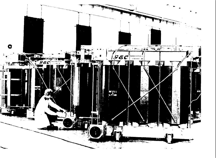
The size and rigidity of the enclosure in relation to that of the transformer usually requires that it be delivered to site separately from the transformer. It is thus necessary to provide it with access doors large enough to enable the transformer to be taken in and out; this operation is simplified by mounting the transformer itself on rollers. The doors also provide access to the interior of the enclosure for the occasional cleaning necessary during service.
Safety for access when installed is ensured by the use of a key interlock arranged such that the enclosure doors can only be opened when the transformer HV circuit-breaker is in the circuit-earthed position.
It is normal CEGB practice to apply a local temporary earth at the point of supply to a dry-type transformer whenever access is gained to the interior of the transformer cubicle. A type of earth connection which is clamped at one end onto a 15 mm diameter bar by means of a remote handling pole is used. The `earthy' end is connected via a length of flexible cable and an earth-end clamp to the switchgear earth bar which must be brought to a suitably accessible point external to the transformer enclosure. With the lineend clamped to the HV connection inside the transformer enclosure and the earth-end clamped outside the enclosure, this ensures that the doors cannot be closed and the HV circuit-breaker released from the `circuit earth' position until the temporary earth has been removed.
For many years, it was considered impracticable to provide a dry-type transformer with any winding temperature indication since, not being immersed in a medium such as transformer oil to which any temperature rise could be referred, it was difficult to obtain
268
Special design features
a reference basis. The best that could be achieved was to place a sensor in a position which it was hoped would
THYRISTOR
e xpoSe it to the hottest cooling air. Thermal image RECTIFIERS devices of the type used in oil-filled transformers
ha' c recently been developed to provide indications of reasonable accuracy. As with the oil-filled equialent, these employ a heater coil having a temperature
rise equal to that of the calculated hot-spot temperature. This surrouna .: a mercury-in-steel thermometer bulb
hich is placed in the hottest outlet air and thus aims :o reflect the true hot-spot temperature. The main problem with such devices is that they require that
the designer should have an accurate knowledge of
POSITIVE
what the hot-spot temperature will be, which may not necessarily be so.
2.4.4 Special transformers
Because of the requirement for a neutral connection on 415 V systems, both for earthing and to enable 240 V single-phase loads to be supplied, transformers stepping down to this voltage level are almost invariabb. star connected on the LV side, with a delta connection on the primary (see Section 1.1.1 of this chapter). The exception is when the low voltage side supplies
significant amount of rectifier load, as in certain electrolytic gas production plants. For very large rectifier loads, the magnitude of harmonic currents drawn from the supply can result in considerable distortion of the supply voltage waveform, particularly if the loads from a number of parallel rectifiers are all drawing harmonics in phase with each other. The problem is unlikely to occur for smaller loads such as battery chargers or for battery-backed inverter systems for computer and instrumentation supplies.
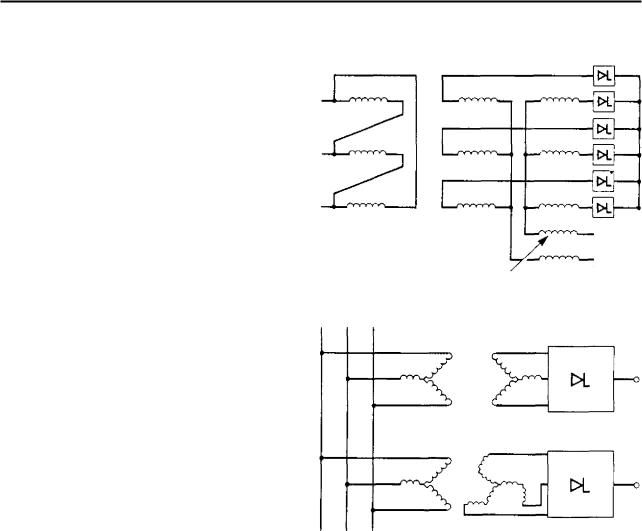
Many rectifier transformers employ a 'six-phase' delta/star/star connection arrangement as shown in Fa2 3.67 (a) and this of itself helps to reduce harmonic distortion by elimination of even harmonics. However an improved arrangement can be obtained by doubling the number of supply transformers and providing half or these with an interconnected star (Fig 3.67 (b)). - 1 . his aims to displace half the rectifier load, and its acsociated harmonic currents, by 30 so as to reduce the resultant magnitude of any given harmonic current drawn from the supply. Although elimination of harmonics generated by thyristor loads has not yet become a major problem for power station auxiliary systems, it is an increasing one due to the growth in the use of thyristor drives and there is considerable literature on the subject, for example, Electricity Council Engi-
neering Recommendation 05/3 [14] and in the technical press (15].
The subject of avoidance of harmonic distortion ol power supplies caused by converter equipment is Important. It is dealt with in detail in Electricity Council
Report ACE 15 [16].
In most other respects rectifier transformers are transformer. The
NEGATIVE
INTERPHASE CHOKE
(a) Six-phase rectifier transformer
(b)12 pulse rectifier using star/star and Starinterstar transformers and full wave bridge rectifier
Eio. 3.67 'Six - phase' rectifier transformer and rectifier transformer bank of delta/star and interstaristar transformers
harmonic currents referred to above can produce additional heating. Also, with certain connection arrangements, polyphase transformers can be subjected to a DC component of current in their secondary windings so that temperature rise tests should be carried out, if possible, in conjunction with the associated rectifier. These transformers are almost invariably dry-type, class C, so that they can be installed indoors in a cubicle adjacent to the rectifier.
Another special requirement of some small auxiliary transformers is that of low magnetising inrush current. The existence of a large magnetising inrush current is normally regarded as an inevitable feature of a power transformer. The phenomenon is dealt with in some detail in many text books [2]. For the largest transformers, it must be allowed for when selecting protection settings; for smaller transformers, supply fuses need to be suitably rated to avoid spurious failure. Normally this represents no more than a minor
269
Transformers |
Chapter 3 |
|
|
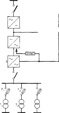
inconvenience. However, a recent application has led to the specification of a specially low magnetising inrush current for certain small instrument supplies transformers as used in uninterruptible power (UPS) supplies systems. Figure 3.68 shows a UPS system which can be fed either from the battery-backed inverter, or from the mains should this fail. Fuses Fl, F2 must be set low in order to protect the inverter from damage in the event of load-side faults. However, these fuses are subjected to the magnetising current of the transformers (Ti and T2) on operation of the changeover switch (S) that provides the continuity of supply from the mains in the event of failure of the inverter. For a system employing an 8 kVA transformer, a fuse rating of 25 A is required to provide the necessary protection for the inverter. The peak magnetising inrush current at 415 V for a transformer of this size would normally be over 200 A. To avoid operation of the fuse it is necessary to ensure that the first peak magnetising current does not exceed about 140 A. The other limiting factor which makes the transformer specification somewhat exacting is that, because of the nature of the loads fed from such a UPS system, the transformer impedance must not exceed about 2 07o to meet regulation requirements. Such transformers can be designed, albeit with difficulty. Achievement of the requirement is assisted by operation at low flux
415V SUPPLY
OATTERY
CHARGER
IN
BATTERY
STA TIC SWITCH
415.110V TRANSFORMERS
110V UPS DISTRIBUTION BOARDS
FIG. 3.68 UPS system with inverter or mains-fed transformer
density (about 1 T) and by the use of a primary winding which has a large air cross-section in relation to the iron cross-section of the core. Hence this winding is usually made the outer winding of a double-concentric arrangement.
The magnitude of the first peak inrush current is dependent on the remanent flux within the core at the instant of energisation and the precise point on the applied voltage wave at which this takes place. The inrush is greatest when switch-on is at voltage zero with the remanent flux within the core at its maximum value and in the opposite sense to that appropriate to the applied voltage. The chances of this occurring for any single random switching is low, hence, in order to carry out an effective proving test it is necessary to use a point-on-wave switching device and to ensure that the core is suitably magnetised.
2.4.5 Foil windings
During the latter part of the 1960s, the price of copper rose steeply and threatened to rise still further, so a number of manufacturers began to experiment with aluminium for transformer windings, mainly in small distribution transformers up to about 500 kVA: the majority of these had foil windings. In addition to avoiding the need for welded joints in wire, this arrangement has the attraction for the manufacturer that windings can be machine wound and, once the machine has been set up, can be produced very rapidly.
There is no record of these transformers so far being used in power station applications. However, the subject is worth mentioning in a section dealing with power station auxiliary transformers since their introduction remains a possibility, particularly in conjunction with a cast-resin insulation system, as noted in Section 2.4.2 of this chapter.
Many users of early foil-wound transformers experienced problems in service arising from the connection between the foils and the risers to the transformer terminals. These frequently involved H V windings where the foil is exceedingly flimsy and the situation is further complicated if HV taps are specified.
The interfoil insulation for foil-wound transformers has been almost exclusively melamine sheet. This is exceedingly thin (less than 0.1 mm) and can be easily punctured by the inclusion of minute particles of dirt or grit, causing failure in service. This can be avoided by manufacturing under clean conditions. There is an additional problem that if the edge of the foil itself is slightly burred or ragged, this too can cause puncture of the melamine. There are also problems of handling the melamine due to the very low coefficient of fricLion between this and aluminium foil. Coils before impregnating require very careful handling and can be very easily 'telescoped out' at this stage. To overcome this there have been attempts to bond the melamine to thin paper to increase the coefficient of friction.
270

Special design features
Another problem with foil-wound HV windings, particularly when delta connected, is that full line, voltage appears across the end of the winding rather than be ing distributed along its length. For this reason and t he problems associated with the use of very thin foil
previously mentioned, some manufacturers have used foil-wound LV windings in conjunction with conven-
tional wire-wound HV windings.
Transformers with aluminium-foil windings have been found not , o be significantly cheaper than those using copper. They have higher losses and at the end of their useful life the aluminium, unlike copper, has
zero scrap value.
A recent development has been the use of copper foil rather than aluminium. This should largely reduce the problem of making connections to the foil, but the benefit of low material cost is sacrificed. It would seem that the attraction is simply that of reduced manufacturing cost by simplification and of something approaching mass production being applied to the winding process.
2.5 Neutral earthing
2.5.1 Generator earthing transformers — basic principles
The practice of earthing the neutral of large generators via a high resistance was developed in the 1950s with the object of restricting stator earth fault current to a low value and thereby limiting the damage caused by the fault. The aim with the system currently in use is to limit the current for an earth fault on the windings of a 23.5 kV generator to between 10 and 15 A. This requires a resistance of about 1400 2. If connected directly into the generator neutral a resistor of this value for such a low rated current would tend to be rather flimsy as well as expensive. The solution is to use a resistor of low ohmic value to load the secondary of a transformer whose primary is connected in series with the generator neutral earth connection. When the system was first devised the intention was o use a standard low cost single-phase distribution transformer. Since that time, generator voltages and ratings have increased considerably and the need for hiv.h security means it is no longer possible to use such a transformer.
The following section describes the special characteristics of generator neutral earthing transformers v.hich have been developed at the present time. For a detailed description of the protection aspects the reader is referred to Chapter 11 of this volume.
The generator neutral connection to the primary of an earthing transformer, or any other high resistance neutral earthing device, must be kept as short as possible since this connection is unprotected. An earth tault on this connection would go undetected until a second fault occurred on the system and then an un-
restricted fault current would flow. It is thus necessary to locate the neutral earthing transformer adjacent to the generator neutral, and an oil-filled transformer cannot be used because of fire hazard. A transformer of high reliability with low fire risk is needed. Poly- chlorinatedbiphenyl-filled transformers were initially used for this purpose but these are now excluded on environmental grounds. In other low fire-risk applications, the CEGB uses class C insulated dry-type transformers, but these are most prone to failure if suddenly energised after a long period in a de-energised condition, which is just the condition applied to a generator neutral earthing transformer in the event of a system earth fault. In 1976, the CEGB decided that this was an ideal application for a cast-resin transformer and therefore drew up a specification for such a transformer. After extensive testing of a prototype, the system was adopted for the earthing of the Dinorwig generators and has become the standard arrangement for subsequent stations.
2.5.2 Generator neutral earthing transformers
— general design features
The detailed requirements for generator neutral earthing transformers are set out in the CEGB Generation Design Memorandum (Plant) No 80. For the neutral of a 23.5 kV, 660 MW generator a voltage ratio of 33/0.5 kV is selected. The primary voltage insulation level of 33 kV corresponds to that used for the generator busbars (see Chapter 4 of this volume) thus maintaining the high security against earth faults. It also ensures an adequate margin of operating voltage over that which could appear on the generator neutral under AVR field-forcing conditions (assumed to be 1.4 times normal volts) with an earth fault on one of the generator line terminals. With this field-forcing condition, the nominal 10 A earth fault current becomes 14 A, hence the transformer should have a rating of 14 x 33 000 = 462 kVA. However this only needs a five-minute rating, since an earth fault of this magnitude would lead to instantaneous operation of the generator protection.
The required continuously rated current is that which is just too low to operate the protection, plus an allowance for third-harmonic currents which may flow continuously in the generator neutral. The aim is to protect as much of the generator windings as possible and so the minimum current for operation is made as low as possible. This is taken to be 53/4 of the nominal setting of 10 A, i.e., 0.5 A. Tests on 660 MW turbine-generators suggest that the level of third-har- monic current is about I A. The transformer continuous rating is thus (0.5 + 1) x 33 000 = 49.5 kVA. In practice a typical transformer of this size has a continuous rating of 0.2-0.25 of the five-minute rating, hence the continuous rating is accommodated naturally.
271
Transformers |
Chapter 3 |
|
|
2.5.3 Practical arrangement
The generator neutral earthing transformer should be located as close as possible to the generator neutral. For modern 500 and 660 MW machines the neutral star-point is formed in aluminium busbar located underneath the neutral end of the generator, usually at the turbine hall basement level. It is housed in a sheet-aluminium enclosure which provides protection tor personnel from the operating voltage as well as electromagnetic protection to the surrounding plant from the large flux generated by the high machine phase currents. (This is described in greater detail in Chapter 4.) The neutral earthing transformer in its enclosure, which usually also houses the resistor, is arranged to abut the neutral enclosure in such a way as to enable a short 'jumper connection' to be made from a palm on the generator star-bar to one on the transformer line-end terminal via suitably located openings in the neutral enclosure and transformer enclosure. On generators 4, 5 and 6 at Drax power station, the transformer was made with long flexible connections to the secondary loading resistor and arranged so that it can be 'racked forward' towards the 2enerator star-bar once transformer and resistor have been placed adjacent the neutral enclosure, thus enabling a very short connection indeed to be made between the star-bar and the transformer. A generator neutral bar and its earthing connection is shown in Fig 3.69.
2.5.4 Loading resistor
The value of apparent resistance required in the generator neutral is V/Irs.s3 0, where V is the generator li ne voltage and Jr the specified stator fault current. When referred to the low voltage side of the transformer, this becomes V/v 2 1 0./3 0 where v is the turns ratio of the transformer.
Inserting the values already given for a 660 MW
23.5kV generator gives a resistance value of about
0.30. Strictly speaking this is the total secondary resistance including that of the transformer, but since a transformer of the rating quoted above has an equivalent resistance of >0.01 ohms, this can be neglected within the accuracy required.
It is also necessary that the X/R ratio for a transformer/resistor combination does not exceed 2, in order to ensure that the power factor of arcing ground faults is as high as possible and that re-striking transients are kept as low as possible.
In fact, a practical transformer meeting the other
parameters specified above can fairly easily be designed to have a reactance of about 4 07o based on the rating
of 462 kVA for the transformer of a 23.5 kV, 660 MW unit which equates to 0.0025 0. This would give an X value of about 0.08, assuming the resistor to be non-inductive, and would allow the resistor to have considerable inductance before causing any embarrassment. The CEGB Design Memorandum states that the
resistor should be non-inductive but this is simply erring on the side of caution and ensuring that there is no likelihood of the maximum X/R value being exceeded inadvertently. Generally, a non-inductive resistor would be flimsier than one which has some inductance because of the construction needed to give this characteristic. Economics might therefore dictate that the resistor is allowed to have some inductance: if so, it is important to know its magnitude and to ensure that the permissible X/R ratio is not exceeded. Typical forms of construction of both inductive and non-inductive resistor elements are shown in Fig 3.70.
The resistor rating can be calculated on the basis of I 2 R, where I equals 924 A, equivalent to a primary current of 14 A, and R equals 0.3 ohms. This works out to about 260 kVA, which is usually rounded up to 300 kVA and is the required five-minute rating. This is not equal to the five-minute rating of the transformer, since the latter has been based on a notional voltage of 33 kV rather than the actual applied voltage of (1.4 x 23.5)/V3 = 19 kV.
The resistor must also have a continuous rating. For the example quoted, this is 1.5 A in the transformer primary or 99 A in the secondary, giving about 3 kVA for a 0.3 0 resistor. As with the transformer, a resistor which can meet the five-minute rating easily satisfies the continuous rating.
Other parameters of the loading resistor are conventional for metal resistors of this type. It must be housed in a sheet steel enclosure which provides protection against personnel access and accidental contact. This can be a common enclosure with the transformer, as indicated in Fig 3.69. However, if a common enclosure is used, there should be a metal barrier between resistor and transformer so that the transformer is protected from any directly radiated heat from the resistor. The external temperature rise of the enclosure after operation must not exceed about 80 ° C to avoid possible injury to anyone coming into contact with it.
2.5.5 Generator busbar system earthing
In an installation having a generator circuit-breaker, a second earth must be provided for the 23.5 kV system, otherwise the system on the transformer side of the generator circuit-breaker would be unearthed when the generator circuit-breaker was open (see Fig 3.71). This earth must have an impedance of a similar order to that of the generator neutral earth; if not, the benefits from high resistance earthing of the generator neutral would be lost. Hence, a second transformerconnected resistor is needed. However, first it is required to provide a neutral for connection to earth. This is obtained using an interconnected-star arrangement (see Section 1.1.3 of this chapter) for connection to the 23.5 kV system. The neutral point thus produced is then connected to the primary of the neutral earthing transformer. The most convenient location for connection to the 23.5 kV system is via a tee-off from
272