

reading / British practice / Vol D - 1990 (ocr) ELECTRICAL SYSTEM & EQUIPMENT
.pdfSpecial design features
GENERATOR Yrs
DISTRIBUTION BOARD
E2T:
-
A . P A
:
RELA , - T Ar, '
I I I I
qELA, |
|
1 |
|
|
|
||
|
|
|
|
|
55 |
riCA ■ SA l L A ' |
|
r.1 E.TIAwA |
s, lEON. AN |
|
|
|
|
|
|
|
!.:EGA.VATT |
TARIFF |
|
|
|||
|
5 |
|
ND.EATIDNS |
|
|
SRNCYPONPSINC. |
|
|
|
|
METERING |
|
|||
L.7.AE |
.1 - ac,. • |
|
LO5C CONTROL 2 |
|
|
|
|
|
|
|
|
|
|||
|
|
|
|
|
|||
|
|
|
|
|
|
|
|
_i _ _ — ,, |
/ |
|
|
-&' |
EJ65 |
|
|
|
I |
|
|
|
|
|
OPP: DELTA BURDEN |
|
|
|
IF RECL, PED |
--- |
I |
|
|
---—. |
|
|
|
|
-0- - - - - - - - - - - - - - - - E E5. |
-- |
|
ET.
E '
|
Ail T OMA, 'DC vOLTAGE |
OVEFIFLLAING PROTECTION |
|
LOW FORwAn. |
REGULATOR CHANNEL A |
MO.TNTED ON RELAY °ANEL |
|
POWER RELAY |
|
POLE SLIPPING PROTECTION |
|
|||
|
J..1 TECiF.AL |
|
ANL) VOLTAGE |
|
O |
FiLfYiNG CONTROL |
OVER UNDER FREOUENCY |
|
SUPPLY |
PROTECTION S. VOLTAGE |
|
|||
AND FUSE PAIL DEL, CE |
|
SUPERVISION RELA', |
||
|
|
ELIPFA_Y SLIPER'i!SIGN RELAY |
|
|
|
|
|
|
|
|
|
|
|
|
|
|
|
|
|
|
|
|
|
|
|
|
|
|
|
|
|
|
|
|
|
|
|
|
|
|
|
|
|
|
|
|
|
|
|
|
|
|
|
|
|
|
|
|
|
|
|
|
|
|
|
|
|
|
|
|
|
|
|
|
|
|
|
|
|
|
|
|
|
I |
|
|
|
|
|
|
|
|
|
|
|
|
|
|
|
|
|
|
|
|
|
|
|
|
|
|
|
|
|
|
|
|
|
||
|
|
|
|
|
I ' 24 ' |
|
|
|
I2 Li" L., 2 A |
' |
|
|
|
|
|
|
||||||
|
|
|
|
|
|
|
|
|
|
|
|
- |
- |
|
|
|
|
|
|
|
||
|
|
|
|
|
|
|
|
|
|
I |
|
I |
|
I |
|
I |
|
|
|
I |
||
|
|
|
|
AuTC3:,9ATIC +TC, |
|
1:DVERFLUXING |
PROTECDO- N |
|
|
|
|
|
||||||||||
|
|
|
|
LTAGE |
I |
VOUNTED ON RELAY PANEL |
|
LOLA FORWARD |
||||||||||||||
|
|
|
|
PEGLILATCP CHANNEL |
LOSS OF EXCITATION |
|
||||||||||||||||
|
|
|
|
|
Pov..ER RELAY |
|||||||||||||||||
|
|
|
|
|
|
.t:TE;RRAL |
, pc:01N.:C 'NON DIRECTIONAL |
|
SUPPO' |
|||||||||||||
|
|
|
|
:ERF,WONG CONTROL |
I CVEPCLiPPENT PROTECTION |
|
||||||||||||||||
|
|
|
|
SUPERV I SION RELAY |
||||||||||||||||||
|
|
|
|
AND TL.rSE DE |
EP |
|
|
|
VOLTAGE SUPPLY |
|||||||||||||
|
|
|
|
|
|
|
|
|
|
|
|
|||||||||||
|
|
|
|
|
|
|
|
|
|
51;P•TRyisirrN 4 |
R", |
|
|
|
|
|
||||||
FIG. 3:78 (cont'd) Generator VT connection arrangement
283
Transformers |
Chapter 3 |
|
|
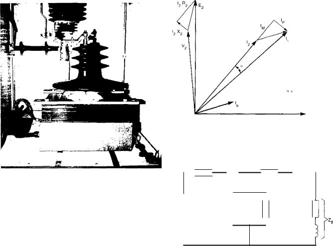
Flo. 3.79 Generator voltage transformer
(except in certain specific circumstances, which will be dealt with later).
The amount by which the transformation ratio departs from the ideal value is:
Phase angle error
0
Flu. 3.80 Phasor diagram for current transformer
(N 2 p4 1 )2 z Load
0
PRIMARY SUPPLY
VOLTS
[(Ka — Kn)/K,J 100% |
(3.9) |
where K T, is the turns ratio of the ideal transformer, given by N2/N1 and K a is the effective turns ratio given by 11/12.
It should be noted that this differs from the definition of current ratio errorgiven by BS3938: 1973[19J which is:
[(K0I2 — Ii)/II] 100 07o |
(3.10) |
i.e., the current which is assumed to be flowing in the primary on the basis of the measured current in the secondary (I2), minus the current actually flowing (1 ) divided by I. This becomes
[(Kn — Ka)/K a ] 100% |
(3.11) |
MIMI is not the same as Equation (3.9) but, since the difference between K n and K a is usually small compared with both K, and K a , for practical purposes this will appear the same. The term 'current ratio error' is often abbreviated to simply 'ratio error'.
The phase angle error is the angle between the phasors representing the primary current and the secondary current reversed. This is conventionally taken as
FlG. 3.81 Conventional equivalent circuit for transformer
positive when the secondary current phasor reversed leads the primary current phasor.
Since there is a wide band of primary currents within which the transformer will operate below saturation then, provided the secondary current remains within that determined by the rated burden, it is possible for the current transformer designer to make some correction for the ratio error. For example, if it were required to design a CT having the ratio 1000: I, and over the operating range the ratio error varied in magnitude between 0.2% and 0.5% then, by using 998 turns on the secondary for a single primary turn, the actual error over the operating range would be minimised. From this, it will be seen that the larger the number of primary turns, the greater the accuracy with which compensation can be carried out. Such compensation does not, of course, affect the phase-angle error.
It will be evident from the above that reduction of the current and phase angle errors can be obtained for any given operating condition by reducing the exciting
284
Special design features
ri.• ••■•• ■•
ampere-turns in relation to the secondary winding ampere-turns. This can be achieved by shortening the flux.path and increasing the cross-sectional area of the core. Hence, ideally, a ring construction having the smallest practical diameter and greatest practical cross-
section should be used.
A significant reduction in errors can be achieved by increasing the number of turns on primary and secondary windings. The reason for this is that, assuming no change in burden, the secondary EMF necessary to circulate the required secondary current remains constant. However, if this is induced into an increased number of turns, the volts/turn are reduced, the flux density is reduced and hence the exciting current, which is the source of the error, will be reduced. It can be shown that provided operation is within the linear part of the magnetisation curve, the error is approximately inversely proportional to (turns) 2 . This is an approximate relationship since, as with power transformers, no parameter can be changed in isolation from all others. Increasing the number of turns inevitably increases the resistance of the secondary winding, thus needing an increased EMF to circulate the required current. This can be offset by increasing the conductor cross-section but since this itself increases the length of mean turn, only partial benefit results.
The above also emphasises the benefits to be gained by minimising secondary burdens so that, although the impedance of relays or other equipment cannot be changed, leads can be made as large as practicable, thereby minimising voltage drops.
At this point it is appropriate to identify and examine the different requirements of current transformers for measurement and protection purposes.
BS3938: 1973 defines the accuracy classes of measurement current transformers in much the same way as does BS3941 for voltage transformers. Classes 0.1, 0.2, 0.5, 1, 3 and 5 have permitted current errors of ±0.1, ±0.2, ±0.5, ±1, ±3 and ±5% respectively at 120 070 of rated current. (Permitted errors are also quoted for intermediate currents. The full range is shown in Tables 3.3 and 3.4.) The performance during fault
or transient conditions is not of interest for most measurement applications; in fact it might be advantageous if the CT saturates under these conditions, since this limits the overvoltage applied to the connected equipment.
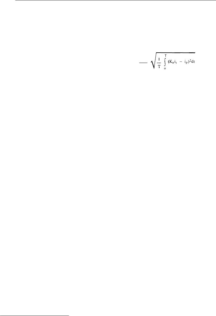
For protective current transformers, the performance under fault conditions is critical and for these the concept of composite error is introduced in BS3938. This is defined as:
100
(3.12)
p
where the symbols and suffixes have the same meanings as defined above except that i, and i p are instantaneous values. T is the period of one cycle of the supply.
As can be seen, this expression has the form of an RMS quantity and takes into account the harmonic content and phase shift of the secondary current. Composite error is defined at the rated accuracy limit primary current which may be several times the rated primary current. The ratio of accuracy limit current to the rated current is known as the accuracy limit factor. Protective CT classes are defined in accordance with their permitted composite errors and BS3938 lists Classes 5P and 10P having composite errors of 5 and 1007o respectively. The corresponding permitted current errors at rated current are ± 1% and +3%.
For protective CTs, a high degree of absolute accuracy is not important, provided that a reasonable degree of accuracy is obtained at the required overcurrent level. For this reason, turns compensation is not generally applied to such transformers.
The above remarks are mainly applicable to protective CTs used for overcurrent protection. For most other protection applications, the most important feature is the maximum useful EMF which can be obtained from the CT under system fault conditions. In this context BS3938 defines the knee point EMF of
TABLE 3.3
Limits of error for current transformers accuracy for Classes 0.1 to 1
|
± percentage current (ratio) |
|
± phase displacement at percentage of rated curren |
|
|||||
|
|
|
shown below |
|
|
||||
|
error at percentage of rated |
|
|
|
|
||||
|
|
|
|
|
|
|
|||
|
current shown below |
|
|
|
|
|
|
||
Class |
|
minutes |
|
|
centiradians |
|
|||
|
|
|
|
|
|
|
|||
|
|
|
|
|
|
|
|
|
|
|
10 up to |
20 up to |
100 up to |
10 up to |
20 up to |
100 up to |
10 up to |
20 up to |
100 up to |
|
but not |
but not |
120 |
but not |
but not |
120 |
but not |
but not |
120 |
|
incl. 20 |
incl. 100 |
|
incl 20 |
incl 100 |
|
incl |
incl 100 |
|
|
|
|
|
|
|
|
|
|
|
0.1 |
0.25 |
0.2 |
0.1 |
10 |
8 |
5 |
0.3 |
0.24 |
0.15 |
0.2 |
0.5 |
0.35 |
0.2 |
20 |
15 |
10 |
0.6 |
0.45 |
0.3 |
0,5 |
1.0 |
0.75 |
0.5 |
60 |
45 |
30 |
1.8 |
1,35 |
0.9 |
|
2.0 |
1.5 |
1.0 |
120 |
90 |
60 |
3,6 |
2.7 |
1.8 |
|
|
|
|
|
|
|
|
|
|
285
Transformers |
Chapter 3 |
|
|
TABLE 3.4
Limas of error for current transformers accuracy for Classes 3 and 5
|
± percentage current (ratio) |
|
Class |
error at perc ntage of rated |
|
|
current sh own below |
|
|
|
|
|
50 |
100 |
|
|
|
3 |
3 |
3 |
5 |
5 |
5 |
|
|
|
the CT as 'That sinusoidal EMF of rated frequency applied to the secondary terminals ... which, when increased by 10 6/o, causes the exciting current to increase by 50 07o'. CTs specified in terms of knee point FMF (as well, of course, as rated primary current and turns ratio) are designated Class X Protective Current Transformers by BS3938 and are permitted a turns ratio error of +0.25 07o.
2.7.4 Current transformer construction
Current transformers for measurement and protection purposes are required throughout a power station auxiliary system. Most frequently it is convenient to locate these within switchgear, for which the barprimary arrangement is the most suitable in terms of strength and simplicity.
Current transformers used on generator voltage busbar systems are also, in effect, bar-primary devices with features developed specifically to meet the requirements of the system. Figure 3.69 shows current transformers at the neutral end of a 660 MW generator. It is necessary to wind the secondary turns on the very large diameter toroidal core in order to provide the air clearance required to meet the 70 kV power frequency, 170 kV impulse-withstand insulation levels of the generator busbars. For a 660 MW machine, the rated busbar current is 20 000 A so that, if the final secondary current is to be 5 A, a ratio of 20 000: 5 is required. With a bar-primary, 4000 secondary turns would thus be needed and some manufacturers consider it more economic to carry out this transformation in t wo stages. Main CTs installed at the generator busbars having a ratio of, say, 20 000: 20 are used in conjunction with additional interposing transformers of ratio 20 5. The interposing transformers are pre-
ferably located as close as possible to the generator busbars to minimise the length of leads required to carry 20 A.
3 |
References |
[ 1 1 |
British Standards Institution: BS171: Specification for power |
|
transformers: 1970 |
121 |
Blume L. F., Boyajian A., Carnifli G., Lennox T. C., Mined |
|
S. and Montsinger V. M.: Transformer Engineering: John |
|
Wiley and Sons |
( 3 1 |
British Standards Institution: BS1432: Specification for copper |
|
for electrical purposes. Strip with drawn or rolled edges: 1970 |
Montsinger V. M.: Loading transformers by temperature: Trans. AIEE Vol 49 pp 776: 1930
BS Code of Practice CP1010: Loading guide for oil-immersed transformers: 1975
Shroff D. H. and Stannett A. W.: A review of paper aging in power transformers: Proc. 1EE, Vol 132, Part C, No.6: November 1985
Franklin A. C. and Franklin D. P.: The 3 and P Transformer Book, 11th Edition: Butterworths: 1983
British Standards Institution: BS5750: Quality systems:
Part 1: Specification for design, manufacture and installation: 1979
Part 2: Specification for manufacture and installation: 1979 Part 3: Specification for final inspection and test: 1979 Part 4: Guide to the use of BS5750, Part 1: 1981
Part 5: Guide to the use of BS5750, Part 2: 1981 Part 6: Guide to the use of BS5750, Part 3: 1981
19J International Electrotechnical Commission: Publication 76, Power Transformers
[10]British Electricity Boards Specification: BEBS-T2: Specification for transformers and reactors: 1966
111] The Electricity Council: Document IT: Guide on impulse testing power transformers and reactors
[12]British Standards Institution: BSI48: Specification for unused mineral insulating oils for transformers and switchgear
1984
[131 Wilson A. C. M.: Insulating liquids and their uses, manufacture and properties: Peter Peregrinus Ltd
1141 The Electricity Council: Recommendation G.5/3: Limits for harmonics in the UK electricity supply system: September 1976
[15]Corbyn D. B.: This business of harmonics: Electronics and Power, Vol 18 pp 219-223: 1972
[16]The Electricity Council: Report ACE15: Harmonic distortion caused by converter equipment
[17]British Standards Institution: BS3941: Specification for voltage transformers: 1975 (1982)
[18]Wright A.: Current transformers, their transient and steady state performance: Chapman and Hall Ltd
[19]British Standards Institution: BS3938: Specification for current transformers: 1973 (1982)
286

CHAPTER 4
Generator main connections
1Introduction
1.1Evokition
2Principles of isolated phase busbar operation and forces encountered
2.1Principles
2.2Forces
2.3Voltage rise
3Designing an IPB system
4Forced cooling
4.1Forced air cooling
4.2Liquid cooling
4.3Water cooling
5System description
5.1Line end
5.2Neutral end
5.3Tee-offs
5.4Delta connections
5.5Excitation busbars
5.6Earth bar
6Setting out the specification
7Component parts of an IPB system
7.1Conductor and enclosures
7,2 Equipment enclosures
7.3 Insulators
7.3.1 Post insulators
7,3.2 Foot insulators (including enclosure supports)
7.3.3Disc bushings
7.3.4Wall seals
7.3.5Bellows
7.4Conductor and enclosure expansion joints 7 5 Flexible connectors
7.5.1Flexible laminae connectors
7.5.2Braided flexible connectors
7.6Painting
7.7Conditioned air
7.8Voltage transformers
7.9Current transformers
7.10Environmental conditions
7.11Portable earth access covers
7.12Viewing ports
7.13Connection of the conductor to plant
7.14Joints in the conductor
7.15On-load temperature measurement 7,16 VT cubicles
7.17Access platforms
7.18Structural steelwork
7.19Neutral earthing equipment
7.20Site installation
7.21Quality assurance
8 Testing
8.1 Tests on component parts
8.1.1Insulators and bushings
8.1.2Busbar material
8.1.3Transformers
8.1.4Loading resistors
8.1.5Capacitors
8.1.6Switchgear and earthing switches
8.1.7Compressed air system
8.2Tests on representative sections of IPB
8.3Test levels
8.4Tests at site
9 Experience of testing
10 Generator voltage switchgear
11Earthing
12Earthing for maintenance purposes
12.1Primary earth
12.2Portable drain earths
13Protection
14Interlocking
15Future trends
15 References
1 Introduction
The principal function of the Main Connections Busbar System is to connect the generator to its associated
generator transformer and, incidentally, to provide a convenient means of connecting the Unit electrical
system to the Unit transformer, via a tee-off. It is present day practice, for reasons explained later, to use an aluminium tube for each phase conductor (or
busbar), which is surrounded by a concentric enclosure of the same material and similar conducting crosssectional area; each is effectively isolated from its neighbour, hence the term isolated phase busbar (IPB). British practice (1988) uses dry conditioned air at a pressure slightly above atmospheric as the insulating medium between the conductor and enclosure.
The conductor is supported at the centre of the enclosure by insulators; these are equispaced and rigidly
287

Generator main connections |
Chapter 4 |
|
|
fixed around the circumference of the enclosure but allow limited radial movement of the conductor. The rating of the main connections installation is established on the basis of temperature rise above a specified ambient at maximum commercial load and its ability to withstand both three-phase short-circuit and earth fault conditions anywhere on the generator voltage system without damage. These requirements introduce some complication in the system design in order to achieve high integrity. Isolated phase busbars have evolved over a number of years, having originally been pioneered in the USA and further developed in France before their introduction in the UK in the mid-1960s. They represent 3-4% of the total cost of the connected generator and transformers. A typical installation is shown in Fig 4.1.
1.1Evolution
There has been extensive development of generator connection designs since their introduction because of larger generating sets and the consequential increase in load and fault currents. Clearly a cable connection to the machine is simplest, but both current and temperature limit their use to about 120 MW (assuming a generator terminal voltage of approximately 23 kV). Consequently, for larger machines, three bare copper conductors (one/phase) were introduced, supported by single insulators at regular intervals and enclosed within a common duct or enclosure (Fig 4.2 (a)). Aluminium gradually replaced copper for the conduc-
tor, primarily on economic grounds, once aluminium welding techniques had improved. The duct or enclosure only excluded gross pollution and prevented physical contact, giving no protection against phase- to-phase faults or the electromagnetic forces between conductors. Strong magnetic fields from this arrangement could cause overheating of external steelwork adjacent to the busbars, increasing system losses.
As currents increased, phase barriers made of either a metallic or insulating material were introduced to li mit the consequences of phase-to-phase flashover (Fig 4.2 (b)). Further improvement was achieved by the use of phase segregation, using a continuous metallic fabricated-aluminium enclosure and barrier, the barrier being integral with the enclosure (Fig 4.2 (c)).
Whilst phase segregation offered an improved design compared with the original common enclosure, it still had a number of weaknesses. Phase-to-phase faults were still possible because adjacent phase conductors share a common barrier. Complicated circulating currents in the enclosure produced forces between conductor and enclosure because no attempt had been made to isolate the busbars magnetically, and the assembly generally became large and exacting to construct. Such designs were used for generators up to 500 MW before new designs were introduced to deal with the shortcomings of phase segregation. These are insulated by enclosing each phase in its own conducting metal tube separate from its neighbours; hence the name isolated phase busbars'. In an installation of this type, eddy currents are induced in the enclosure, or sheath, due
|
|
|
|
ifFItiglio |
|
\ |
),--,, |
EXCITER |
liklir |
|
|
|
|
CONNECTIONS |
EARTH |
|
|
|
|
|
r- |
|
|
|
|
|
SWITCH |
|
|
|
|
i |
, |
|
|
NEUTRAL |
\ |
|
|||
|
|
||||
CONNECTIONS |
|
|
|||
\ |
GENERATOR |
|
|
t-, |
|
|
CONNECTIONS |
|
|
|
|
,A... .-..:a. |
|
|
|
|
|
|
,...- |
|
|
|
|
\ |
I1 i, |
|
|
|
UNIT |
|
|
|
|
|
TRANSFORMER |
|
|
|
|
|
EARTHING |
|
|
|
|
VT |
TRANSFORMER |
|
|
|
|
|
|
|
|
|
|
CUBICAL |
|
|
|
EXCITER |
ISOLATED |
|
|
|
|
PHASE |
|
||
|
|
FIELD |
|
||
|
|
ASSEMBLY |
|
||
|
|
SW/TCH |
|
||
|
|
EXCITER |
|
||
|
ni |
|
|
|
|
|
NEUTRAL RECTIFIER |
|
|||
|
EARTHING |
|
|
||
|
MODULE |
|
|
||
FIG. 4.1 Generator main connections — general arrangement of a typical installation
288
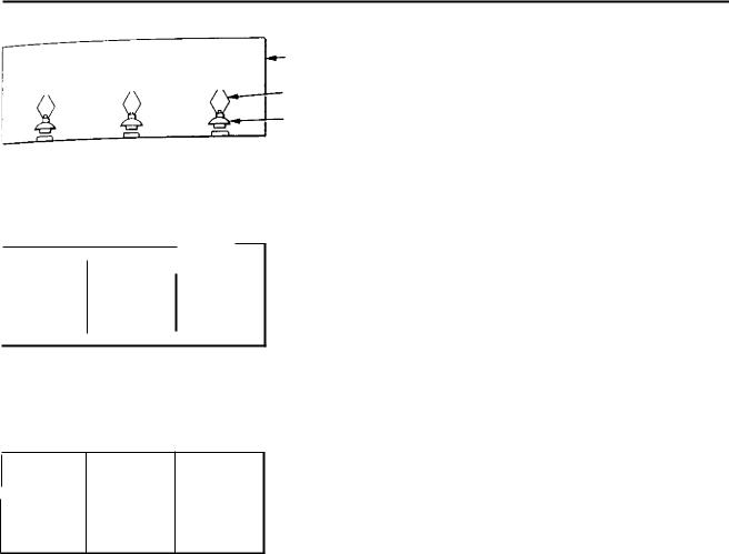
Principles of isolated phase busbar operation and forces encountered
OUCT OR
ENCLOSURE
CONDUCTOR
SUPPORT
INSULATOR
z1NTERPHASE BARRIERS
,r. ETALLIC OR INSULATING,
^+E., -& ea , egalea DS |
Darr.er$ |
CONTINUOUS METALLIC FABRICATED ENCLOSURE aNCUJOING BARRIERS
Ph3se seg•egated sus C; \
INSULATING FEET
FIG. 4.2 Segregated and non-segregated busbars
to the conductor current, and this to some extent shields I he forces between the conductors by modifying the field around the conductor. There are, however, still
substantial magnetic fields outside the enclosure, which produce forces between phases. These are reduced con-
siderably if the extreme ends of each phase enclosure are bonded together, thereby allowing a balanced cur-
rent flow in the enclosures of all three phases. This system is known as an 'electrically - continuous IPB with
short-circuit' (see Fig 4.3). Each phase enclosure is made electrically continuous throughout its length and all three are connected together at both ends of the run. This distinguishes it from other systems, namely the insulated type (where the enclosure is not continuous hut includes non-conducting sections) or the continuous
[ Me with saturable impedance, where the continuous phase enclosures are connected together at the ends of
the run through small saturable reactors which limit the induced longitudinal currents to a design value. The last-named appears attractive because the reactor limits the enclosure circulating currents during normal opera- ti on, thereby reducing the enclosure losses, and during
fault conditions the reactor saturates, reducing its impedance to circulating currents and allowing greater enclosure current to flow. As will be explained later, this enclosure current reduces the forces between conductors during fault conditions. However, in practice, the reactors tended to burn out, so now only the elec- trically-continuous 1PB with short-circuit is considered in the UK and elsewhere. These, by virtue of the enclosure circulating currents, limit forces between phase conductors to approximately 10 07o of those that would exist without the enclosure.
The enclosure system is earthed at one point only and is insulated from earth along its length by supporting it on insulated foot mountings, thereby giving control over the path followed by any fault current in the enclosure. Clearly the main connections have now become a system in their own right and to control the circulating currents, as described, the enclosures must be isolated from all items of plant to which the conductors are connected. Enclosures are therefore connected to auxiliary plant via rubber bellows which maintain the physical protection of the conductor but isolate the enclosures electrically from the plant. The bonding or short-circuiting of the enclosures is done as close to the end of their run as possible. The external magnetic fields produced by the conductor currents can link with conducting loops in the adjacent steelwork, producing circulating currents and heat. This is a problem to be considered by the designer since excessive heat, in addition to being an unnecessary system loss, can cause unacceptable expansion and can be a hazard to personnel if the steelwork is touched.
Machines of 660 MW are now used extensively in the UK and an IPB installation of the type described provides an adequate main connections design which can be naturally cooled and is of manageable size. This probably represents the limit of naturally cooled designs and any significant increase in machine rating will mean that forced-cooled designs will have to be considered. The components of one phase of such a system are shown diagrammatically in Fig 4.4.
2 Principles of isolated phase busbar operation and forces encountered
2.1Principles
Consider, using simple analysis, how the magnetic fields may be reduced. When a conductor carries an alternating current, it produces an external concentric alternating magnetic field, the direction of which is determined by application of the 'corkscrew' rule. If another conductor runs parallel to it, then an EMF is induced in it, given by e = — (c1(1)/dt), where cl) is that proportion of the flux linking the two conductors. The negative sign indicates that it tries to oppose the force which created it.
289
Generator main connections |
Chapter 4 |
|
|
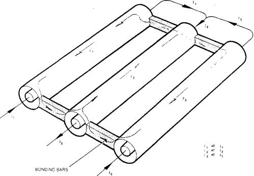
FG. 4.3 Phase isolated busbar — continuous sheath
For a length of isolated phase busbar, the voltage Se induced in an elemental section of non-continuous sheath (say, SA and SB in Fig 4.5 (a)) due to the current flowing in its associated conductor will be the same magnitude for all elements on the circumference of the sheath at any point along its length. It follows, therefore, that one phase in isolation can have no current flow in the sheath, since the voltages at all points are equal.
If next, the condition in Fig 4.5 (b) is considered, the voltage e induced in an elemental section of noncontinuous sheath due to the current flowing in an adjacent conductor will be of different magnitude for each position around the periphery (say, SC and SD), since each element cuts a different proportion of flux from that conductor. Therefore, unequal voltages are available to cause current to flow in the sheath as shown in Fig 4.6 (a). This sheath current, which for the elemental circuit shown in Fig 4.6 (a) can be considered as a simple `go' and 'return' circuit, will set up an electromagnetic field whose direction can be determined by application of the corkscrew rule. This will give rise to a reduction of field within the enclosure but a reinforcement of the field outside as shown in Fig 4.6 (b). Thus the, e is a reduction of forces between the conductors and an increase in forces exerted on the enclosure. The enclosure will therefore need substantial supports.
The currents circulating in each sheath caused by the proximity effects of adjacent conductor systems are termed 'eddy currents'. Formulae for determining these currents and their associated losses have been proposed by H. B. Dwight in 1923 and F. W. Carter
in 1927. In the paper by Carter [I], the eddy current was determined by considering the fixed distribution of conductor currents but taking into account the magnetic field set up by the induced eddy current in the sheath itself. This first order eddy current was then determined for neighbouring sheaths and these were used as a fixed distribution to obtain second and further subsidiary eddy currents in the original sheath. The process may be repeated to any degree of approximation to obtain a total eddy current. In Dr Carter's day, the problem did not merit meticulous calculation and the treatment was therefore simplified by considering only the first order eddy current to produce results in a convenient form for hand calculation. Working independently, Dr Dwight tackled a number of proximity effect problems and in 1923 published a first order eddy current solution [2] for sheath eddy loss which is identical to the Carter solution. Later, in 1964, the analysis was extended to determine the subsidiary eddy currents for the particular case of a single-phase circuit and also a three-phase flat grouping.
Since the non-continuous type of IPB is not used by the CEGB, the theory is not developed here, but the reader may deduce the necessary formulae from papers [1 and 2].
Now consider the continuous type of IPB. If the sheaths of all three phases are electrically connected at each end of the IPB run, an external path is provided which allows the sheath currents to flow in the manner shown in Fig 4.3. The phase conductors and the enclosures are comparable to the primary and secondary turns of a short-circuited transformer. The
290
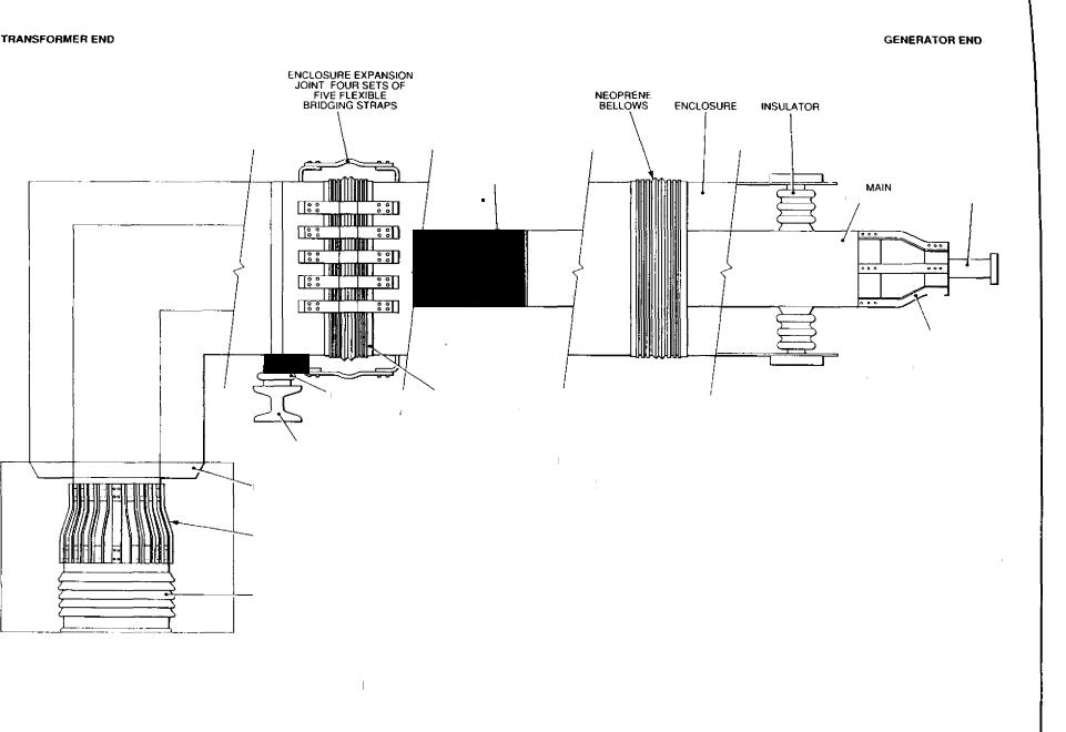
TRANSFORMER END |
|
|
|
|
|
|
|
|
|
|
|
|
|
|
|
|
|
|
|
GENERATOR END |
|
|
|
|
|
|
|
|
|
|
|
|
|
|
ENCLOSURE EXPANSION |
|
|
|
|
|
|
|
|
|
|
JOINT FOUR SETS OF |
|
|
|
|
|
|
|
|
|
|
FIVE FLEXIBLE |
|
NEOPRENE |
|
|
|
|
|
|
|
|
BRIDGING STRAPS |
|
BELLOWS |
|
ENCLOSURE |
|
INSULATOR |
|
|
- |
|
|
|
|
MAIN |
CONDUCTOR |
|
|
|
11"v""....a----...din7_ |
1 |
|
GENERATOR |
|
EXPANSION JOINT |
|
|||
|
|
|
MAIN |
TERMINAL |
CONDUCTOR STALK
|
III! |
|
|
...1 |
000 |
Str. |
"1".1 |
|
Jr.
INSULATED BELLOWS
FOOT
SUPPORTING
STEELWORK
DISC BUSHING
CONDUCTOR
TERMINAL PALMS
(EIGHT OFF)
TRANSFORMER
BUSHING
NOTE THIS IS A DIAGRAMMATIC COMPOSITE TO ILLUSTRATE THE MAIN SYSTEM COMPONENTS IT IS NOT A
TYPICAL ARRANGEMENT AND IS
NOT DRAWN TO SCALE
TERMINAL
CANDELABRA CONNECTIONS (ONLY 3 SHOWN)
Fici. 4.4 Phase isolated busbar — main components
encountered forces and operation busbar phase isolated of Principles

Generator main connections |
Chapter 4 |
|
|
|
• |
• |
• |
B O., |
Al nil |
• |
• |
• |
• |
• |
• |
|
• |
;a) induced voltages in an enclosure due to its own conductor
• |
• |
• |
|
||
•D • |
|
.c |
• |
0 |
|
• |
|
• |
• |
• |
• |
|
|
a
magnetic field produced by the primary conductor induces a current of opposite direction in the secondary turn. The magnitude of the circulating sheath current is almost equal to the conductor current, depending on the resistance and reactance of the enclosure circuit, and is in antiphase to the conductor current. The sheath current usually amounts to about 90% of the conductor current.
The circulating sheath current creates its own surrounding magnetic field which must be in antiphase to that produced by the conductor, thus the magnetic field still exists within the enclosure but is cancelled outside it (see Fig 4.6 (c)). Since the enclosure has resistance, the resultant external magnetic field around each conductor is about 10% of that which would occur if there was no metallic sheath.
Since the external magnetic field has been reduced, it follows that the forces between conductors are also reduced by a similar proportion, as will be the forces between enclosures that exist due to the current flowing in them.
CD However, end effects occur where the conductor is connected to its associated piece of plant and is, for practical reasons, unshielded. Therefore magnetic fields at these points are much stronger and forces greater. For further analysis, the reader is referred to a paper by Skeats and Swerdlow [3].
2.2 Forces
(b)Induced voltages in an enclosure due to an adjacent conductor
Fin. 4.5 Induced voltages in an enclosure
The forces caused by short-circuit and earth fault currents are very complex. Neglecting decrements, a totally-offset short-circuit current can be represented
ENCLOSURE
EDDY
CURRENTS
(a} Enclosure eddy currents in a phase isolated buster • dscontinuous sheath
FIG. 4.6 Radial current flows due to current in an adjacent conductor
292