

2338 |
CHAPTER 29. CLOSED-LOOP CONTROL |
29.11.7Foxboro model 130
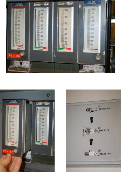
Foxboro also manufactured panel-mounted pneumatic controllers, the model 130 series, for largerscale applications where multiple controllers needed to be located in one compact space. A bank of four Foxboro model 130 pneumatic controllers appears in the next photograph:
Each controller may be partially removed (slid out) from its slot in the rack, the P, I, and D settings adjustable on the left side panel with a screwdriver:
29.11. PNEUMATIC PID CONTROLLERS |
2339 |
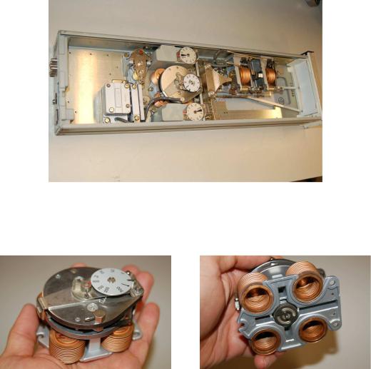
With the side panel removed, the entire mechanism is open to viewing:
The heart of the model 130 controller is a four-bellows force-balance mechanism, identical in principle to the hypothetical force-balance PID controller mechanism used throughout the explanatory discussion. Instead of the four bellows acting against a straight beam, however, these bellows push against a circular disk:
2340 |
CHAPTER 29. CLOSED-LOOP CONTROL |
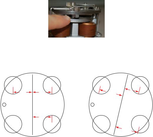
A nozzle (shown in the next photograph) detects if the disk is out of position (unbalanced), sending a back-pressure signal to an amplifying relay which then drives the feedback bellows:
The disk rocks along an axis established by a movable bar. As this bar is rotated at di erent angles relative to the face of the disk, the fulcrum shifts with respect to the four bellows, providing a simple and e ective gain adjustment:
Gain is equal to 1 (PB = 100%)
Gain exceeds 1 (PB < 100%)
PV |
|
Feed- |
|
back |
|
|
|
|
PV moment |
Feedback moment |
|
Nozzle |
arm |
arm |
|
|
|
SP moment arm
SP
PV |
|
Feed- |
|
back |
|
|
moment |
|
PV |
Feedback |
|
Nozzle |
arm |
arm moment |
|
|
SP |
moment |
SP |
|
||
|
|
|
|
arm |
|
If the moment arms (lever lengths) between the input (PV and SP) bellows and the feedback bellows are equal, both sets of bellows will have equal leverage, and the gain will be one (a proportional band setting of 100%). However, if the fulcrum bar is rotated to give the input bellows more leverage and the feedback bellows less leverage, the feedback bellows will have to “work harder” (exert more force) to counteract any imbalance of force created by the input (PV and SP) bellows, thus creating a greater gain: more output pressure for the same amount of input pressure.
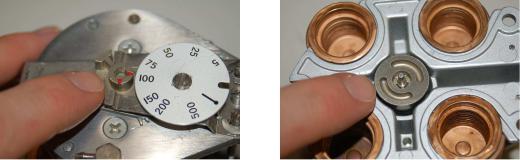
The fourth (lower-left) bellows acting on the disk provides an optional reset (integral) function. Its moment arm (lever length) of course is always equal to that of the feedback bellows, just as the PV and SP bellows’ moment arm lengths are always equal, being positioned opposite the fulcrum line.
29.11. PNEUMATIC PID CONTROLLERS |
2341 |
Selection between direct and reverse action works on the exact same principle as in the Fisher MultiTrol controller – by connecting four air ports in one of two paired configurations. A selector (movable with a hex wrench) turns an air signal port “switch” on the bottom of the four-bellows unit, e ectively switching the PV and SP bellows:
An interesting characteristic of most pneumatic controllers is modularity of function: it is possible to order a pneumatic controller that is proportional-only (P), proportional plus integral (P+I), or full PID. Since each control mode requires additional components to implement, a P-only pneumatic controller costs less than a P+I pneumatic controller, which in turn costs less than a full PID pneumatic controller. This explains the relative scarcity of full PID pneumatic controllers in industry: why pay for additional functionality if less will su ce for the task at hand?
29.11.8External reset (integral) feedback
Some pneumatic controllers come equipped with an option for external reset: a feature useful in control systems to avoid integral windup if and when the process stops responding to changes in controller output. Instead of receiving a pneumatic signal directly from the output line of the controller, the reset bellows receives its signal through another pneumatic line, connected to a location in the control system where the final e ect of the output signal (m) is seen. If for some reason the final control element cannot achieve the state called for by the controller, the controller will sense this through the external reset signal, and will cease integration to avoid “wind-up.”
2342 |
CHAPTER 29. CLOSED-LOOP CONTROL |
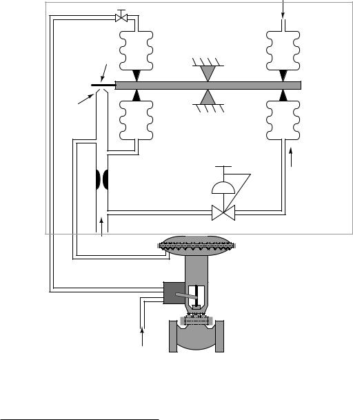
In the following illustration20, the external reset signal comes from a pneumatic position transmitter (ZT) mounted to the sliding stem of the control valve, sending back a 3-15 PSI signal representing valve stem position:
Process variable signal
(3-15 PSI)
Reset adjust |
Controller |
Baffle |
Gain adjust |
|
|
|
Lever |
Nozzle |
|
|
Setpoint adjust |
|
Setpoint signal |
|
(3-15 PSI) |
Air supply |
|
|
Control valve |
Position transmitter |
|
ZT |
|
External reset line
Air supply
If something happens to the control valve causing it to freeze position when the controller commands it to move – suppose the stem encounters a mechanical “stop” limiting travel, or a piece of solid material jams the valve trim so it cannot close further – the pneumatic pressure signal sent from the position transmitter to the controller’s reset bellows will similarly freeze. After the
20In case you are wondering, this controller happens to be reverse-acting instead of direct. This is of no consequence to the feature of external reset.