


2190 |
CHAPTER 27. CONTROL VALVES |
27.12.3Gas valve sizing
Sizing a control valve for gas or vapor service is more complicated than for liquid service, due to the compressibility of gases and vapors. As a gas or vapor compresses with changes in pressure, its density changes correspondingly. In previous mathematical analyses of fluid flow restriction, one of our assumptions was that fluid density (ρ) remained constant. This assumption may hold true for some flowing gas conditions as well, provided minimal pressure changes within the path of flow. However, for most gas control valve applications where the very purpose of the valve is to introduce substantial pressure changes, the assumption of constant gas density is unrealistic.
Shown here is one of the simpler gas valve sizing equations you will encounter:
s
Q = 963 Cv
P (P1 + P2)
Gg T
Where,
Q = Gas flow rate, in units of Standard Cubic Feet per Hour (SCFH) Cv = Valve capacity coe cient
P = Pressure dropped across valve, pounds per square inch di erential (PSID) P1 = Upstream valve pressure, pounds per square inch absolute (PSIA)
P2 = Downstream valve pressure, pounds per square inch absolute (PSIA) Gg = Specific gravity of gas (ratio of gas density to standard air density)
T = Absolute temperature of gas in degrees Rankine (oR), equal to degrees Fahrenheit plus 459.67
This equation holds true only for “subcritical” flow, where the moving gas stream velocity never approaches the speed of sound35. Other equations exist for calculating flow rates of gas through control valves in the presence of sonic flow regimes. Note the inclusion of absolute pressures in this equation, and not just di erential pressure (ΔP , or P1 − P2). This is intended to correct for e ects related to compression of the gas under pressure.
Valve sizing is complicated enough, both for liquid and gas service, that the use of valve sizing computer software is strongly recommended as opposed to hand-calculations. The number of important parameters, nonlinear factors, and alternative equations relevant to control valve sizing are numerous enough to bewilder most technicians (and more than a few engineers). Valve sizing software will also predict noise levels generated by the valve, and in many cases specify actual valve trim styles o ered by the manufacturer for mitigating problems such as noise.
35The ISA Handbook of Control Valves cites this equation as being valid for conditions where the valve’s downstream pressure (P2) is equal to or greater than one-half the upstream pressure (P1), with both pressures expressed in absolute units. In other words, P2 ≥ 0.5P1 or P1 ≤ 2P2. An upstream:downstream pressure ratio in excess of 2:1 usually means flow through a valve will become choked.
27.12. CONTROL VALVE SIZING |
2191 |
27.12.4Relative flow capacity
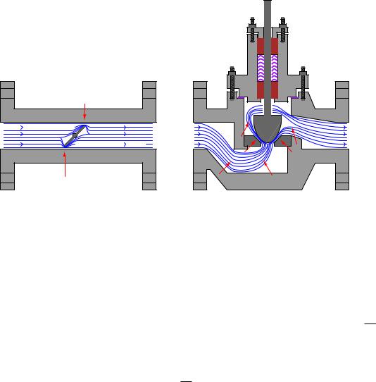
The flow capacity of a valve (Cv ) is a quantitative rating of its ability to pass a fluid flow for a set of given pressure and fluid density conditions, defined as the flow rate of water in gallons per minute through the valve given a constant pressure drop of 1 PSID. Cv may be predicted, or empirically measured, for any type of control valve given the proper information.
Not all control valve types exhibit the same Cv coe cients, however, for the same pipe size. A 4 inch butterfly valve, for example, has a much greater full-open Cv rating than a 4 inch globe valve, due to the much more direct path it o ers to a moving fluid. A simple comparison of these two valve types clearly shows why this is true (note the “constriction” points labeled with arrows):
Globe valve
Butterfly valve
Note: red arrows show points of maximum fluid energy loss
A globe valve is simply more e ective at generating fluid turbulence – and therefore dissipating fluid kinetic energy – than a butterfly valve of the same pipe size, because the globe valve design forces the fluid to change direction more often and in di erent ways.
One way to help quantify a particular valve design’s ability to throttle fluid flow is to express this ability as a ratio of flow coe cient (Cv ) versus cross-sectional pipe area. The basic principle here is that we should expect the Cv of any particular valve design to be proportional to pipe area (e.g. a ball valve with twice the pipe area should have twice the flow capacity, all other factors being equal), and therefore a ratio of these two quantities should be fairly constant for any valve design. Since we know the area of a pipe is proportional to the square of either radius or diameter (A = πd42 or A = πr2), we may simplify this ratio by omitting all constants such as π and simply relating Cv factor to the square of pipe diameter measured in inches (d2). This ratio is called the relative flow capacity, or Cd:
Cv
Cd = d2