

28.2. AC MOTOR SPEED CONTROL |
2249 |
28.2AC motor speed control
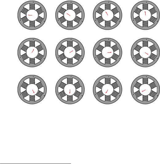
AC induction motors are based on the principle of a rotating magnetic field produced by a set of stationary windings (called stator windings) energized by AC power of di erent phases. The e ect is not unlike a series of blinking “chaser” light bulbs which appear to “move” in one direction due to the blinking sequence. If sets of wire coils (windings) are energized in a like manner – each coil reaching its peak field strength at a di erent time from its adjacent neighbor – the e ect will be a magnetic field that “appears” to move in one direction. If these windings are oriented around the circumference of a circle, the moving magnetic field rotates about the center of the circle, as illustrated by this sequence of images (read left-to-right, top-to-bottom, as if you were reading words in a sentence):
|
A |
|
|
A |
|
|
A |
|
|
A |
B |
|
C |
B |
|
C |
B |
|
C |
B |
C |
|
|
|
|
N |
|
|
N |
|
|
N |
N |
S |
|
N |
|
|
N |
|
|
||
|
S |
|
|
|
N |
N |
||||
N |
S |
|
N |
S |
|
|
S |
|
S |
S |
C |
|
B |
C |
S |
B |
C |
S |
B |
C |
S |
|
|
|
B |
|||||||
|
A |
|
|
A |
|
|
A |
|
|
A |
|
A |
|
|
A |
|
|
A |
|
|
A |
B |
|
C |
B |
|
C |
B |
|
C |
B |
C |
|
N |
|
|
N |
|
|
|
|
|
S |
|
N |
|
S |
N |
|
S |
N |
|
S |
N |
S |
|
|
S |
N |
|
S |
N |
|
S |
N |
C |
S |
B |
C |
S |
B |
C |
|
B |
C |
N |
|
|
|
B |
|||||||
|
A |
|
|
A |
|
|
A |
|
|
A |
|
A |
|
|
A |
|
|
A |
|
|
A |
B |
|
C |
B |
S |
C |
B |
|
C |
B |
C |
|
S |
|
|
|
|
S |
|
|
S |
|
|
|
|
|
|
|
|
S |
|||
S |
|
|
S |
S |
|
|
S |
|
N |
|
|
N |
|
N |
N |
|
N |
|
|
N |
S |
C |
N |
B |
C |
N |
B |
C |
N |
B |
C |
N |
|
|
|
B |
|||||||
|
A |
|
|
A |
|
|
A |
|
|
A |
To view a flip-book animation of this same sequence, turn to Appendix A.2 beginning on page 2856.
Any magnetized object placed in the center of this circle will attempt to spin at the same rotational speed as the rotating magnetic field. Synchronous AC motors use this principle, where a magnetized rotor precisely follows the magnetic field’s speed.
Any electrically conductive object placed in the center of the circle will experience induction as the magnetic field direction changes around the conductor. This will induce electric currents within the conductive object, which in turn will react against the rotating magnetic field in such a way that the object will be “dragged along” by the field, always lagging a bit in speed. Induction AC motors use this principle, where a non-magnetized (but electrically conductive) rotor rotates at a speed slightly less5 than the synchronous speed of the rotating magnetic field.
5The di erence between the synchronous speed and the rotor’s actual speed is called the motor’s slip speed.

2250 |
CHAPTER 28. VARIABLE-SPEED MOTOR CONTROLS |
The rotational speed of this magnetic field is directly proportional to the frequency of the AC power, and inversely proportional to the number of poles in the stator:
S = 120f n
Where,
S = Synchronous speed of rotating magnetic field, in revolutions per minute (RPM) f = Frequency, in cycles per second (Hz)
n = Total number of stator poles per phase (the simplest possible AC induction motor design will have two poles)
The relationship between synchronous speed, frequency, and pole number may be understood by analogy: the speed at which the lights in a “chaser” light array appear to move is a function of the blinking frequency and the number of light bulbs per unit length. If the number of light bulbs in such an array is doubled by placing additional bulbs between the existing bulbs (so as to maintain the same array length), the apparent speed will be cut in half: with less distance between each pair of bulbs, it takes more cycles (more “blinks”) for the sequence to travel the entire length of the array. Likewise, an AC stator with more poles in its circumference will require more cycles of AC power for the rotating magnetic field to complete one revolution.
A synchronous AC motor will spin at the exact same speed as the rotating magnetic field: a practical example is a 4-pole synchronous motor spinning at 1800 RPM with an applied power frequency of 60 Hz. An induction AC motor will spin at slightly less than the speed of the magnetic field: a practical example is a 4-pole induction motor spinning at 1720 RPM with an applied power frequency of 60 Hz (i.e. 80 RPM “slip” speed). Induction motors are simpler both in construction and operation, making them the most popular of the two types of AC electric motors in industry.
While the number of poles in the motor’s stator is a quantity fixed6 at the time of the motor’s manufacture, the frequency of power we apply may be adjusted with the proper electronic circuitry. A high-power circuit designed to produce varying frequencies for an AC motor to run on is called a variable-frequency drive, or VFD.
Variable-frequency motor drives are incredibly useful devices, as they allow what would normally be a fixed-speed electric motor to provide useful power over a wide range of speeds. The benefits of variable-speed operation include reduced power consumption (only spinning the motor as fast as it needs to move, and no faster), reduced vibration (less speed = reduced vibrational forces), and the ability to ramp the motor’s speed up and down for reduced wear and tear on mechanical components resulting from acceleration forces.
Another feature common to most VFDs is the ability to actively brake the load. This is when the drive causes the motor to actively apply a negative torque to the load to slow it down. Some VFDs even provide means to recover the kinetic energy of the load during the braking process, resulting in further energy savings.
6Multi-speed motors do exist, with selectable pole configurations. An example of this is an electric motor with extra sets of stator windings, which may be connected to form a 4-pole configuration for high speed, and an 8-pole configuration for low speed. If the normal full-load “high” speed for this motor is 1740 RPM, the normal full-load “low” speed will be approximately half that, or 870 RPM. Given a fixed line frequency, this motor will only have these two speeds to choose from.

28.2. AC MOTOR SPEED CONTROL |
2251 |
Variable-frequency AC motor drives consist of electronic components to convert the constantfrequency AC input power into variable-frequency (and variable-voltage) AC output power for the motor to run on. This usually takes place in three distinct sections. The rectifier section uses diodes to convert line AC power into DC. The filter “smoothes” the rectified DC power so it has little ripple voltage. Lastly, the inverter section re-converts the filtered DC power back into AC, only this time at whatever levels of frequency and voltage is desired to run the motor at di erent speeds.
A simplified schematic diagram for a VFD is shown here, with a rectifier section on the left (to convert AC input power into DC), a filter capacitor to “smooth” the rectified DC power, and a transistor “bridge” to switch DC into AC at whatever frequency is desired to power the motor7. The transistor control circuitry has been omitted from this diagram for the sake of simplicity:
|
Filter |
|
Rectifier section |
section |
Inverter section |
From |
Positive (+) DC bus |
|
three-phase |
||
|
||
AC power |
|
|
source |
|
|
|
AC |
|
|
motor |
|
|
Negative (-) DC bus |
As with DC motor drives (VSDs), the power transistors in an AC drive (VFD) switch on and o very rapidly with a varying duty cycle. Unlike DC drives, however, the duty cycle of an AC drive’s power transistors must vary rapidly in order to synthesize an AC waveform from the DC “bus” voltage following the rectifier. A DC drive circuit’s PWM duty cycle controls motor power, and so it will remain at a constant value when the desired motor power is constant. Not so for an AC motor drive circuit: its duty cycle must vary from zero to maximum and back to zero repeatedly in order to create an AC waveform for the motor to run on.
7Note the reverse-connected diodes across the source and drain terminals of each power transistor. These diodes serve to protect the transistors against damage from reverse voltage drop, but they also permit the motor to “back feed” power to the DC bus (acting as a generator ) when the motor’s speed exceeds that of the rotating magnetic field, which may happen when the drive commands the motor to slow down. This leads to interesting possibilities, such as regenerative braking, with the addition of some more components.
2252 |
CHAPTER 28. VARIABLE-SPEED MOTOR CONTROLS |
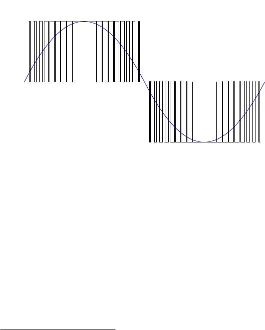
The equivalence between a rapidly-varied pulse-width modulation (PWM) waveform and a sine wave is shown in the following illustration:
This concept of rapid PWM transistor switching allows the drive to “carve” any arbitrary waveform out of the filtered DC voltage it receives from the rectifier. Virtually any frequency may be synthesized (up to a maximum limited by the frequency of the PWM pulsing), and any voltage (up to a maximum peak established by the DC bus voltage), giving the VFD the ability to power an induction motor over a wide range of speeds.
While frequency control is the key to synchronous and induction AC motor speed control, it is generally not enough on its own. While the speed of an AC motor is a direct function of frequency (controlling how fast the rotating magnetic field rotates around the circumference of the stator), torque is a function of stator current. Since the stator windings are inductors by nature, their reactance varies with frequency as described by the formula XL = 2πf L. Thus, as frequency is increased, winding reactance increases right along with it. This increase in reactance would result in decreased stator current if the VFD’s output voltage remained constant. This undesirable scenario would result in torque loss at high speeds, and excessive torque (as well as excessive stator heat!) at low speeds. For this reason, the AC voltage output by a VFD is made to vary8 in proportion to the applied frequency, so that the stator current will remain within good operating limits throughout the speed range of the VFD. This correspondence is called the voltage-to-frequency ratio, abbreviated “V/F” ratio or “V/Hz” ratio.
To give an example of a VFD programmed with a constant V/F ratio, if the output line voltage to the motor is 480 volts RMS at full speed (60 Hz), then the output line voltage should be 240 volts RMS at half-speed (30 Hz), and 120 volts RMS at quarter-speed (15 Hz).
8The VFD achieves variable output voltage using the same technique used to create variable output frequency: rapid pulse-width-modulation of the DC bus voltage through the output transistors. When lower output voltage is necessary, the duty cycle of the pulses are reduced throughout the cycle (i.e. transistors are turned on for shorter periods of time) to generate a lower average voltage of the synthesized sine wave.
28.2. AC MOTOR SPEED CONTROL |
2253 |
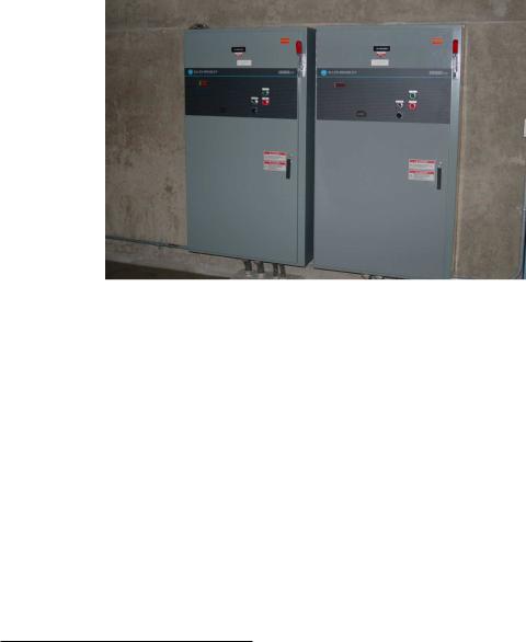
Variable-frequency motor drives are manufactured for industrial motor control in a wide range of sizes and horsepower capabilities. Some VFDs are small enough to hold in your hand, while others are large enough to require a freight train for transport. The following photograph shows a pair of moderately-sized Allen-Bradley VFDs (about 100 horsepower each, standing about 4 feet high), used to control pumps at a wastewater treatment plant:
Variable-frequency AC motor drives do not require motor speed feedback the way variable-speed DC motor drives do. The reason for this is quite simple: the controlled variable in an AC drive is the frequency of power sent to the motor, and rotating-magnetic-field AC motors are frequencycontrolled machines by their very nature. For example, a 4-pole AC induction motor powered by 60 Hz has a base speed of 1728 RPM (assuming 4% slip). If a VFD sends 30 Hz AC power to this motor, its speed will be approximately half its base-speed value, or 864 RPM. There is really no need for speed-sensing feedback in an AC drive, because the motor’s real speed will always be limited by the drive’s output frequency. To control frequency is to control motor speed for AC synchronous and induction motors, so no tachogenerator feedback is necessary for an AC drive to “know” approximately9 how fast the motor is turning. The non-necessity of speed feedback for AC drives eliminates a potential safety hazard common to DC drives: the possibility of a “runaway” event where the drive loses its speed feedback signal and sends full power to the motor.
As with DC motor drives, there is a lot of electrical “noise” broadcast by VFD circuits. Square-edged pulse waveforms created by the rapid on-and-o switching of the power transistors are equivalent to infinite series of high-frequency sine waves10, some of which may be of high enough frequency to self-propagate through space as electromagnetic waves. This radio-frequency interference or RFI may be quite severe given the high power levels of industrial motor drive circuits. For this reason, it is imperative that neither the motor power conductors nor the conductors feeding
9For more precise control of AC motor speed (especially at low speeds where slip speed becomes a greater percentage of actual speed), speed sensors may indeed be necessary.
10This equivalence was mathematically proven by Jean Baptiste Joseph Fourier (1768-1830), and is known as a
Fourier series.