

29.11. PNEUMATIC PID CONTROLLERS |
2333 |
29.11.5Fisher MultiTrol
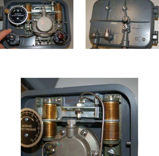
Front (left) and rear (right) photographs of a real pneumatic controller (a Fisher “MultiTrol” unit) appear here:
The mechanism is remarkably similar to the one used throughout the explanatory discussion, with the important distinction of being motion-balance instead of force balance. Proportional and integral control modes are implemented through the actions of four brass bellows pushing as opposing pairs at either end of a beam:
The nozzle may be seen facing down at the middle of the beam, with the center of the beam acting as a ba e. Setpoint control is achieved by moving the position of the nozzle up and down with respect to the beam. A setpoint dial (labeled “Increase Output Pressure”) turns a cam which moves the nozzle closer to or farther away from the beam. This being a motion-balance system, an o set in nozzle position equates to a biasing of the output signal, causing the controller to seek a new process variable value.
2334 |
CHAPTER 29. CLOSED-LOOP CONTROL |
Instead of altering the position of a fulcrum to alter the gain (proportional band) of this controller, gain control is e ected through the use of a “pressure divider” valve proportioning the amount of output air pressure sent to the feedback bellows. Integral rate control is implemented exactly the same way as in the hypothetical controller mechanism illustrated in the discussion: by adjusting a valve restricting air flow to and from the reset bellows. Both valves are actuated by rotary knobs with calibrated scales. The reset knob is actually calibrated in units of minutes per repeat, while the proportional band knob is labeled with a scale of arbitrary numbers:
Selection of direct versus reverse action is accomplished in the same way as selection between proportional and snap-action (on-o ) control: by movable manifolds re-directing air pressure signals to di erent bellows in the mechanism. The direct/reverse manifold appears in the left-hand photograph (the letter “D” stands for direct action) while the proportional/snap manifold appears in the right-hand photograph (the letter “P” stands for proportional control):
29.11. PNEUMATIC PID CONTROLLERS |
2335 |
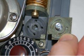
Either setting is made by removing the screw holding the manifold plate to the controller body, rotating the plate one-quarter turn, and re-attaching. The following photograph shows one of the manifold plates removed and turned upside-down for inspection of the air passages:
The two quarter-circumference slots seen in the manifold plate connect adjacent air ports together. Rotating the plate 90 degrees connects the four air ports together as two di erent pairs.
2336 |
CHAPTER 29. CLOSED-LOOP CONTROL |
29.11.6Foxboro model 43AP
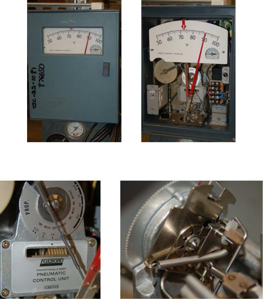
The Fisher MultiTrol pneumatic controller is a very simple device, intended for field-mounting near the pneumatic transmitter and control valve to form a control loop for non-precision applications. A more sophisticated field-mounted pneumatic controller is the Foxboro model 43AP, sporting actual PV and SP indicating pointers, plus more precise tuning controls. The following photographs show one of these controllers, with the access door closed (left) and open (right):
At the heart of this controller is a motion-balance “pneumatic control unit” mechanism. A dial for setting proportional band (and direct/reverse action) appears on the front of the mechanism:
29.11. PNEUMATIC PID CONTROLLERS |
2337 |
Note the simple way in which direct and reverse actions are described on this dial: either increasing measurement, decreasing output (reverse action) or increasing measurement, increasing output (direct action).