


28.4. MOTOR DRIVE FEATURES |
2261 |
28.4Motor drive features
Modern DC and AC motor drives provide features useful when using electric motors as final control elements. Some common features seen in both VSDs and VFDs are listed here:
•Speed limiting
•Current limiting
•Torque limiting
•Torque profile curves (used to regulate the amount of torque available at di erent motor speeds)
•Acceleration (speed rate-of-change) limiting
•Deceleration (speed rate-of-change) limiting
•DC injection braking (applying DC to a motor to turn it into an electromagnetic brake)
•Dynamic braking (turning the motor into an electromagnetic brake12)
•Regenerative braking (turning the motor into a generator to recover kinetic energy)
•Plugging (applying reverse-direction power to a motor to quickly stop it)
•Overcurrent monitoring and automatic shut-down
•Overvoltage monitoring and automatic shut-down
•PWM frequency adjustment (may be helpful in reducing electromagnetic interference with some equipment)
Not only are some of these limiting parameters useful in extending the life of the motor, but they may also help extend the operating life of the mechanical equipment powered by the motor. It is certainly advantageous, for example, to have torque limiting on a conveyor belt motor, so that the motor does not apply full rated torque (i.e. stretching force) to the belt during start-up.
If a motor drive is equipped with digital network communication capability (e.g. Modbus), it is usually possible for a host system such as a PLC or DCS to update these control parameters as the motor is running.
In order for a VSD or VFD to properly and safely control an electric motor, that drive must be programmed with the motor’s nameplate data (voltage rating, current rating, maximum speed, etc.). For AC motors in particular, the base or nameplate parameters of voltage, current, frequency, and shaft speed represent the motor’s expected performance when connected directly to line power (with no VFD), and as such provide essential points of reference for the VFD’s operation. Failure to properly configure an electronic motor drive with these “base” parameters may even result in damage to the motor, for example if the drive is configured to output more current than the motor is rated for! As such, it is recommended that you first program these parameters into a motor drive before setting any other drive parameters.
12This is accomplished in very di erent ways for DC versus AC motors. To dynamically brake a DC motor, the field winding must be kept energized while a high-power load resistor is connected to the armature. As the motor turns, the armature will push current through the resistor, generating a braking torque as it does. One way to dynamically brake an AC motor is to inject a small DC current through the stator windings, causing large braking currents to be induced in the rotor. Another way is to regeneratively brake into a resistive load.
2262 |
CHAPTER 28. VARIABLE-SPEED MOTOR CONTROLS |
28.5Use of line reactors
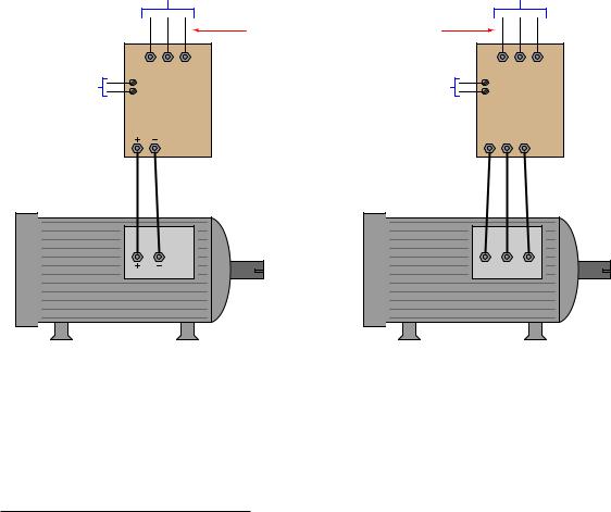
Regulating the electric power sent to an electric motor is a task performed by high-speed switching transistors inside a motor drive, modulating the pulse-width of a high-frequency square wave to the motor. The high-speed switching happening inside of a motor “drive” circuit results in the drive drawing current from the AC power source as high-frequency pulses rather than as sinusoidal waves. These current pulses tend to distort the voltage of the AC power source so that other devices powered by the same AC source will “see” high-frequency noise on the power lines. This is true for DC and AC motor drives alike:
|
3-phase 480 VAC |
|
3-phase 480 VAC |
|||
|
input power |
|
input power |
|||
|
|
High-frequency current and voltage |
|
|
|
|
|
|
"noise" appears at input terminals |
|
|
|
|
Control signal |
L1 L2 L3 |
Control signal |
|
L1 |
L2 L3 |
|
from the output |
Input signal |
from the output |
Input signal |
|||
of a process |
of a process |
|||||
|
|
|
|
|||
controller |
VSD |
controller |
|
VFD |
||
|
(DC motor drive) |
|
(AC motor drive) |
|||
|
|
|
T1 |
T2 |
T3 |
|
DC motor
AC motor
T1 |
T2 |
T3 |
As French mathematician and physicist Jean Baptiste Joseph Fourier (1768-1830) mathematically proved centuries ago, any repeating waveform – no matter how strange the shape may be – is equivalent to a series of sine and cosine waves at integer multiples (“harmonics”) of some fundamental frequency. Thus, the normal sine-wave AC power supplied to an operating motor drive unit will be tainted by harmonic frequencies in addition to the fundamental frequency of 60 Hz13.
Such high-frequency noise may be very troublesome to nearby electronic devices and to other electrical components connected to the same AC power system. Power transformers will su er increased core heating from harmonic currents. System capacitances and inductances may resonate
13In Europe, the fundamental power line frequency is 50 Hz rather than 60 Hz. Also noteworthy is the fact that since the distortion caused by motor drives is typically symmetrical above and below the center-line of the AC waveform, the only significant harmonics will be odd and not even. In a 60 Hz system, the odd harmonics will include 180 Hz (3rd), 300 Hz (5th), 420 Hz (7th), and higher. For a 50 Hz system, the corresponding harmonic frequencies are 150 Hz, 250 Hz, 350 Hz, etc.

28.5. USE OF LINE REACTORS |
2263 |
at these harmonic frequencies causing high currents and voltages to form. So-called triplen harmonics14 are especially troublesome in three-phase power circuits, where they tend to add in the neutral conductors of Wye-connected system components and circulate through the phase elements in Delta-connected system components. In some industrial installations, the magnitude of triplen harmonic currents in a 4-wire Wye system have been so great that the neutral conductor actually overheated from excessive current, even though the three line conductors were well within their rated load current capacities!
14Harmonic voltages and currents whose frequencies are multiples of three of the fundamental (e.g. 3rd, 6th, 9th, 12th, 15th harmonics). The reason these particular harmonics are noteworthy in three-phase systems is due to their relative phase shifts. Whereas the fundamental phase shift angle between di erent phase elements of a three-phase electrical system is 120o, the phase shift between triplen harmonics is zero. Thus, triplen harmonics are directly additive in three-phase systems.
2264 |
CHAPTER 28. VARIABLE-SPEED MOTOR CONTROLS |
One method useful to combat these e ects is to filter harmonic frequencies from the rest of the AC power system, preventing the subsequent “corruption” of the AC power source by the motor drive’s pulsing currents. The most direct way to filter harmonic frequencies is to use an electrical component acting as a low-pass filter – a simple inductor connected in series with the motor drive. For three-phase-powered motor drives, this takes the form of three inductor elements, commonly referred to in industry as reactors:
3-phase 480 VAC
input power
Minimal harmonic noise present on AC power lines
Line reactor
Harmonic noise confined to drive input wiring
L1 L2 L3
Motor drive
Line reactors work by presenting a greater series impedance to high-frequency harmonic currents than to low-frequency fundamental currents, following the inductive reactance formula XL = 2πf L. The greater the frequency (f ) of current, the greater the inductive reactance (XL) and therefore the greater the attenuation of that current through that conductor. As one might expect, line reactors cannot prevent harmonic distortion in the AC power system, but they do a great deal to mitigate the ill e ects of harmonics produced by a motor drive.
28.5. USE OF LINE REACTORS |
2265 |
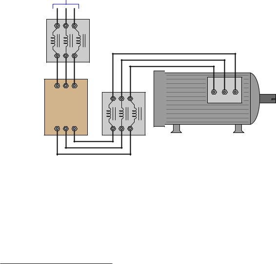
Line reactors may also be used on the output of an AC motor drive to filter harmonics from the motor itself. Like transformers, AC induction motors su er greater core losses when exposed to harmonic currents, causing the motor to heat up more than it would if powered by AC power of one pure frequency:
3-phase 480 VAC
input power
Weak harmonics
Input line reactor
Weak harmonics
AC motor
Strong harmonics!
L1 L2 L3
Motor drive
T1 T2 T3
Output line reactor
Strong harmonics!
The presence of strong harmonic distortion on the motor drive’s input wiring means those conductors should be kept short as possible to minimize electromagnetic interference with nearby electrical and electronic components.
Not only do output line reactors help reduce heating e ects in the AC motors powered by variablefrequency drives, the reactors also reduce the severity of fault currents resulting from short-circuit transistor failures in the motor drive, as well as minimize the ill e ects of reflected signals in the conductors stretching between the output line reactor and the motor itself15. With such benefits arguing for the installation of line reactors in variable-speed motor control circuits, the only reason for their non-installation is added expense, and/or insu cient space inside the enclosure with the motor drive.
15As you may recall, any su ciently long set of conductors will act as a transmission line for high-frequency pulse signals. An unterminated (or poorly-terminated) transmission line will reflect pulse signals reaching its ends. In the case of a motor drive circuit, these reflected pulses may constructively interfere to produce nodes of high voltage or high current, causing premature wiring failure. Output line reactors help minimize these e ects by filtering out high-frequency pulse signals from reaching the long motor power conductors.