

Russian Journal of Building Construction and Architecture
.pdfRussian Journal of Building Construction and Architecture
According to SP (CП) 41-01-95 "Designing Heat Points", the heat transfer coefficient K, W / (m2 K), for plate heat exchangers is calculated:
К |
|
|
|
|
|
, |
1 |
|
1 |
|
СТ |
||
|
1 |
2 |
СТ |
|
||
|
|
|
|
where β is the coefficient taking into consideration the decrease in the heat transfer coefficient due to the thermal resistance of scale and impurities on the plate depending on the quality of the water, is taken equal to 0.7––0.85; α1 is the coefficient of heat transfer from heating water to the plate wall, Watt/(m2 K); α2 is the coefficient of heat absorption from the wall of the plate to the heated water, Watt/(m2 K); δСТ is the thickness of the heat exchange plate, m; λСТ is the coefficient of the heat conductivity of the plate material, Watt/(m2 K).
As a result of the research, the optimal operating modes of the investigated plate heat exchanger with increased turbulization have been identified.
It has been shown experimentally that the use of corrugated plates with spherical depressions arranged according to a linear law causes an increase in the heat transfer coefficient K, W / (m2 K), and an intensification of heat transfer, which is confirmed in Fig. 5.
Heat transfer coefficient, K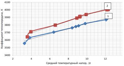
Average temperature pressure, t
Fig. 5. Graph of the dependence of the heat transfer coefficient on the average temperature pressure: 1 –– serial heat exchanger; 2 –– plate heat exchanger with corrugated plates with spherical grooves
It can be concluded that the use of corrugated plates with spherical grooves arranged according to a linear law causes an increase in the efficiency of the plate heat exchange equipment and the overall reduction in the cost of heating (cooling) of the coolant.
Conclusions
1. The use of plates with technological depressions of a spherical shape, arranged according to a linear law, makes it possible to increase the efficiency of heat transfer between two heat car-
60
Issue № 3 (51), 2021 |
ISSN 2542-0526 |
riers, e.g., liquids, by increasing the heat transfer coefficient by intensifying the turbulence of the heat carrier flow in the heat exchanger. In this case, additional vortex formation occurs at the "heat carrier –– plate" interface.
2.Intensification of heat exchange processes is achieved by using spherical grooves located according to a linear law.
3.The results of the experimental studies of two plate heat exchangers confirm the advantage of using modified corrugated plates.
4.It is our belief that further research in the field of intensification of heat exchange processes would increase the reliability of heat supply systems and reduce the maintenance costs.
References
1.Grabezhnaya V. A., Kirillov P. L. Teploobmen pri sverkhkriticheskikh davleniyakh granitsy ukhudsheniya teploobmena [Heat transfer at supercritical pressures limits of heat transfer degradation]. Teploenergetika, 2006, no. 4, pp. 46—51.
2.Zegzhda A. P. Gidravlicheskie poteri v kanalakh i truboprovodakh [Hydraulic losses in channels and pipelines]. Moscow, Gosstroiizdat Publ., 1957. 503 p.
3.Kushchev L. A., Nikulin N. Yu., Feoktistov A. Yu., Yakovlev E. A. Intensifikatsiya teplovykh protsessov v kozhukhotrubnom teploobmennom apparate [Intensification of thermal processes in a shell-and-tube heat exchanger]. Nauchnyi vestnik Voronezhskogo GASU. Stroitel'stvo i arkhitektura, 2016, no. 3, pp. 9—17.
4.Kushchev L. A., Nikulin N. Yu. [Application of heat exchangers in industry]. Materialy mezhdunar. nauch.-prakt. konf “Tekhnosfernaya bezopasnost', nadezhnost', kachestvo, energo- i resursosberezhenie” [Proc. “Technosphere safety, reliability, quality, energy and resource conservation”]. Rostov-on-Don, Izd-vo RGSU, 2015, vol. XVII, iss. 1, pp. 204—210.
5.Lobanov I. E. Modelirovanie teploobmena pri turbulentnom techenii v ploskikh kanalakh s simmetrichnymi turbulizatorami na obeikh storonakh [Modeling of heat exchange during turbulent flow in flat channels with symmetrical turbulators on both sides]. Vestnik Dagestanskogo gosudarstvennogo tekhnicheskogo universiteta. Tekhnicheskie nauki, 2019, no. 1, pp. 53—65.
6.Marksis'ko O. R. Ekonomicheskaya effektivnost' intensifikatsii teploobmena pri ispol'zovanii poverkhnostno-aktivnykh veshchestv [Economic efficiency of heat exchange intensification when using surfactants]. Nauchnyi vestnik LNUVMBT im. S. Z. Ґzhits'kogo, 2015, no. 1, pp. 60—65.
7.Maskinskaya A. Yu. [Experimental and computational studies in a channel with holes on the lower wall]. Tez. dokladov 10-i mezhdunar. nauch.-tekhn. konf. studentov i aspirantov “Radioelektronika, elektrotekhnika i energetika”
[Proc. “Radioelectronics, electrical engineeringandpower engineering”]. Moscow, 2004, pp. 348—349.
8.Noto K., Matsumoto R. Turbulentnyi perenos tepla pri svobodnoi konvektsii vdol' izotermicheskoi vertikal'noi ploskoi poverkhnosti [Turbulent heat transfer under free convection along an isothermal vertical flat surface]. Teploperedacha, 1975, no. 4, 139 p.
9.Kushchev L. A., Savvin N. Yu., Feoktistov A. Yu. Plastina teploobmennika [Heat exchanger plate]. Patent RF, 2020, no. 199344.
61

Russian Journal of Building Construction and Architecture
10.Romanenko V. A. Izmeneniya klimata v Rossii. Prichiny i posledstviya [Climate change in Russia. Causes and consequences]. Molodoi uchenyi, 2019, no. 7, pp. 1—5.
11.Rudskoi A. I., Lunev V. A. Matematicheskoe modelirovanie gidrodinamiki i teploobmena v dvizhushchikhsya zhidkostyakh [Mathematical modeling of hydrodynamics and heat transfer in moving fluids]. SaintPetersburg, Lan' Publ., 2015. 208 p.
12.Savvin N. Yu., Nikulin N. Yu. [Highly efficient heat exchanger for the housing and communal services system]. Sb. nauch. tr. “Nauka. Tekhnologii. Innovatsii” [The science. Technologies. Innovations]. Novosibirsk, NGTU Publ., 2019, pp. 256—262.
13.Savvin, N. Yu. [Improvement of the design of the plate heat exchanger]. Mezhdunar. nauch.-tekhn. konf. molodykh uchenykh [International Scientific and Technical University conf. of young scientists]. Belgorod, BGTU im. V. G. Shukhova, 2020, pp. 2240—2244.
14.Tsygankov A. S. Raschety teploobmennykh apparatov [Calculations of heat exchangers]. Saint-Petersburg, SUDPROMGIZ Publ., 1956. 135 p.
15.Yakovlev B. V. Povyshenie effektivnosti sistem teplofikatsii i teplosnabzheniya [Improving the efficiency of heating and heat supplysystems]. M., Novosti teplosnabzheniya Publ., 2013. 448 p.
16.Gulenoglu. C., Akturk F.,Aradag S., Sezer N., Uzol S. Kakac Experimental comparison of performances of three different plates for gasketed plate heat exchangers. International Journal of Thermal Sciences, 2014, no. 75, pp. 249—256.
17.Gupta A. K., Kumar P., Sahoo R. K., Sahu A. K., Sarangi S. K. Performance measurement of plate fin heat exchanger byexploration:ANN,ANFIS, GA, and SA. Journal of Computational Design and Engineering, 2016, no. 4, pp. 60—68.
18.Huikun C., Lijun S.,Yidai L., Zeju W. Numerical and experimental study on the influence of top bypass flow on the performance of plate fin heat exchanger. Applied Thermal Engineering, 2018, no. 146, pp. 356—363.
19.Kexin X., Robin S., Nan Z. Design and optimization of plate heat exchanger networks. Computer Aided Chemical Engineering, 2017, no. 40, pp. 1819—1824.
20.Khujaev P. S., R. G.Abdullaev, A. J. Rahmonzoda Radiative heat transfer in the furnace space with variable volume. Polytechnic bulletin. Series: Engineering research, 2019, no. 1 (45). pp. 223—227.
21.Kolesnikov I. P., Danilchenko S. E. Modelling of thermoelastic transient contact interaction for binary bearing taking into account convection. Transport Problems, 2016, no. 4, pp. 73—81.
22.Kushchev, L. A., Nikulin N. Yu., Alifanova A. I., Feoktistov A. Yu. Intensity enhancement of heat exchange in shell-tube heat exchangers with smooth pipes. Advances in Engineering Research, 2017, no. 133, pp. 390—395.
23.Moretti R., Errera M., Couaillier V., Feyel F. Effect of the perforation design on the fluid flow and heat transfer characteristics of a plate fin heat exchanger. International Journal of Thermal Sciences, 2018, no. 126, pp. 172—180.
24.Vasil’ev E. N. Calculation of heat transfer characteristics of a finned wall. Siberian Journal of Science and Technology, 2020, no. 2, pp. 226—232.
25.Wang J., Lan S., Chen G. Experimental study on the turbulent boundary layer flow over riblets surface.
Fluid Dyn. Res, 2000, no. 4, p. 27.
26. Wagh Р., Pople M. U. Optimization of a Shell and Tube Condenser using Numerical Method. Int. Journal of Engineering Research and Applications, 2015, vol. 7, pp. 9—15.
62

Issue № 3 (51), 2021 |
ISSN 2542-0526 |
DOI 10.36622/VSTU.2021.51.3.005
UDC 621.642.02
N. N. Osipova1, B. M. Grishin2
MODELING OF OPERATING MODES GAS COMPOSITE CYLINDERS
Saratov State Technical University Named after Gagarin Yu. A.,
Institute of Urban Planning, Architecture and Construction1
Russia, Saratov
Penza State University of Architecture and Construction,
Institute of Engineering Ecology2
Russia, Penza
1D. Sc. in Engineering, Head of the Dept. of Heat and Gas Supply and Oil and Gas, tel.: (8452) 99-88-93, e-mail: osnat75@mail.ru
2D. Sc. in Engineering, Head of the Dept. of Water Supply, Sewerage and Hydraulic Engineering, tel.: (8412) 92-95-08
Statement of the problem. The emergence of composite cylinders on the market offers a range of technological and operational advantages in comparison with metal cylinders of liquefied hydrocarbon gas. At the same time, the absence of substantiated recommendations for determining the vapor capacity of cylinders by modes of their operation in the scientific literature limits their wide implementation intogas practice.
Results. A mathematical model considering the operation of the cylinder in the mode of periodic gas consumption is developed, the coefficient of non-uniformity of gas consumption during the day is calculated, the values of the heat transfer coefficient of the composite cylinder wall are identified, the approximate dependence of the heat transfer coefficient is obtained.
Conclusions. As a result of the research, the criteria influencing steam productivity of composite cylinders of the liquefied hydrocarbon gas in various operating modes are found.
Keywords: composite cylinder, liquefied hydrocarbon gas, periodic gas consumption, steam capacity, heat transfer coefficient.
Introduction. Temporary and periodic (seasonal) gas supply to facilities located remotely from natural gas mains are largely supplied using liquefied petroleum gas (LPG) cylinders while ensuring the use of gas for cooking and hot water preparation [1, 5, 11].
The most common metal gas cylinders with a volume of 5 to 50 liters [9, 18] are the most common. However, these cylinders have considerable disadvantages:
susceptibility to corrosion;
explosion hazard;
©Osipova N. N., Grishin B. M., 2021
63

Russian Journal of Building Construction and Architecture
significant weight of an empty cylinder;
impossibility to control the level of gas in the cylinder due to its opacity.
Composite cylinders are free from these disadvantages as they are easy to store, carry, transport. They have a greater aesthetics and come in a wide range of sizes and shapes. The market for composite cylinders is dominated by manufacturers Rugasco (Russia), Heagon Ragasco
(Norway), Armotech, HPC Research (Czech Republic), Life Safe, Supreme (India) [10].
At the same time, the use of composite cylinders in the household sector requires practical guidelines for identifying the steam capacity of tanks and operating conditions. The available recommendations for metal cylinders in this case are not applicable, and there are no scientific studies to have identified the steam capacityof composite cylinders in the known literature.
The goal of the study is to identify the criteria that affect the steam production of composite cylinders of liquefied hydrocarbon gas under conditions of natural convection of internal air in the room considering the periodic gas consumption and changes in the filling level of the cylinder with the liquid phase of the gas.
1. Development of a mathematical model of periodic gas consumption. Studies [3, 4, 6, 12, 16, 22] show that the steam capacity of containers with gas operating under pressure is identified by a number of technical characteristics with the following major ones:
component composition of gas;
ambient temperature;
minimum filling level of the container;
duration of gas consumption, etc.
With constant extraction of the vapor phase from the cylinder during the day, the calculated steam capacity of the cylinder under the worst operating conditions, kg/h, is given by the formula [4, 15]:
g |
k Fmin (t |
в |
tmin ) |
(1) |
|
cм |
ж |
, |
|||
|
|
|
|||
r
where k is the coefficient of the heat transfer of the cylinder wall, kJ h/m2К; Fcminм is the wetted surface of the cylinder of the liquid gas phase corresponding to the minimum level of its filling, m2; tв is the temperature of the environment, 0С; tжmin is the minimum temperature of the liquefied gas in the cylinder before another filling, 0С; r is the hidden vaporization heat of the liquefied gas, kJ/h.
Under actual operating conditions of cylinders, gas consumption is commonly of a periodic nature, while the periods of evaporation of the liquid phase "I" are changed by the periods of
64
Issue № 3 (51), 2021 |
ISSN 2542-0526 |
rest "O". During the rest period, there is an increase in the temperature of the liquid phase of the gas due to heat exchange with the environment and that in the equilibrium vapor pressure [17, 21]. The heat balance of the specified period can be described by the expression:
kFсмО tв tж d cг MгО cстMстО dt rdG, |
(2) |
where FсмО is the wetted surface of the cylinder corresponding to the rest mode, m2; tж is
the temperature of the liquefied gas, 0С; dτ is change of the time when the rest of the cylinder is examined, h; сг, сст is the heat capacity of the liquefied gas and cylinder walls respectively, kJ/kg К; MгО ,MстО is the mass of the liquid phase of the gas in the cylinder in the rest period and cylinder body contacting with the liquid phase, kg; dt is change of the temperature over the rest period of the cylinder, 0С; G is the mass of the vapour phase in the cylinder, kg.
Assuming that the change in the mass of the liquid and the area of the wetted surface during a separate period of vapor consumption occurs insignificantly, let us assume:
FО |
FИ ; |
|
см |
см |
|
МгО |
МгИ ; |
(3) |
|
МстО МстИ . |
|
|
Then the expression (2) can be presented as follows: |
|
|
|
kFсмИ tв |
tж d cгMгИ |
cстMстИ dt rdG. |
(4) |
An increase in the equilibrium vapor pressure due to additional evaporation of LPG is a se- cond-order value rdG → 0 and may not be taken into consideration in further studies. In this
case, the calculation error does not exceed 2 %.
Then the duration of the rest period of the cylinder is given by the expression:
d |
c MИ c |
MИ |
|
|
dt |
|
|||
г г |
ст |
ст |
|
|
|
|
. |
(5) |
|
|
kFИ |
|
t |
|
|
||||
|
|
|
|
в |
t |
|
|||
|
|
см |
|
|
|
|
|
|
|
The cylinder is heated during the rest process, which takes place in the time interval from 0 to
кон, while the gas temperature in the cylinder changes fromtИ to tО:
кон |
c |
M И c |
M И tО |
|
dt |
||||
d |
г |
г |
ст |
ст |
|
|
|
|
. |
|
|
kFИ |
|
t |
в |
t |
|||
0 |
|
|
см |
|
tИ |
|
|
||
Then, integrating the expression in theaboverangesofparameter variation, we get:
|
|
|
c MИ c |
MИ |
t |
в |
t |
И |
|
||
|
кон |
|
г г |
ст |
ст |
ln |
|
|
. |
||
|
kFИ |
|
|
|
|
|
|||||
|
|
|
|
|
|
|
|
|
|
||
|
|
|
|
см |
|
|
|
|
|
|
|
(6)
(7)
65

Russian Journal of Building Construction and Architecture
Let us express the temperature of the liquefied gas at the end of the rest period:
tО tв |
|
|
tв tИ |
|
, |
(8) |
||
|
kFИ |
|
кон |
|
||||
|
|
|
см |
|
|
|
|
|
ecгMгИ cстMстИ
where е is the Euler’s number.
Intensive vaporization of gas in the cylinder takes place in the process of gas consumption, while the vapor phase is formed partly due to the influx of heat from the environment and a decrease in the temperature of the gas in the cylinder. At the same time, there is a drop in the equilibrium elasticity of saturated vapors.
The heat balance equation of the cylinder during the gas consumption period has the form:
FО |
FИ |
|
MО M И |
MО |
M И |
|
||||||
k |
см |
см |
(tв |
t) cг |
г |
г |
cст |
ст |
ст |
dt rgd . |
||
|
|
|
|
|
|
|||||||
|
|
2 |
|
|
|
2 |
|
|
|
|
2 |
|
|
|
|
|
|
||||||||
Given the assumption (2), the expression (9) takes the form:
kFсмИ (tв t)d cГ MгИ cстMстИ dt rgd .
The duration of the vaporization period is defined as
d cгMгИ cст MстИ dt .
rg kFсмИ (tв t)
(9)
(10)
(11)
The duration of gas evaporation in the cylinder taking into consideration the range of values of the change in time0 d исп :
|
|
|
исп |
tО |
cгMгИ |
cстMстИ dt |
|
|
|
|
|
|
|
||||
|
|
|
|
d |
|
|
|
|
. |
|
|
|
|
(12) |
|||
|
|
rg kFИ (t |
в |
t) |
|
|
|
|
|||||||||
|
|
0 |
tИ |
|
см |
|
|
|
|
|
|
|
|
|
|||
After inserting the limits, we get |
|
|
|
|
|
|
|
|
|
|
|
|
|
|
|||
|
|
|
cг MгИ cстMстИ |
|
rg kFИ (t |
в |
t ) |
|
|||||||||
|
исп |
|
|
|
|
ln |
|
|
см |
|
|
|
О |
|
. |
(13) |
|
|
kFИ |
|
rg kFИ |
(t |
в |
t |
И |
) |
|||||||||
|
|
|
|
|
|
|
|||||||||||
|
|
|
|
см |
|
|
|
|
см |
|
|
|
|
|
|||
Let us transform expression (13) taking into consideration expression (8) identifying the hourly gas consumption by the cylinder:
|
kFИ t |
|
|
|
|
|
|
kFсмИ кон |
|
|
kFсмИ исп |
|
|
|
|
|
t |
|
e cгMгИ cстMстИ |
ecгMгИ cстMстИ |
|
|
|||||||
|
см |
в |
|
И |
|
|
|
|
|
|
|
|
|
|
g |
|
|
|
|
|
|
|
|
|
|
|
|
. |
(14) |
|
|
|
|
|
|
|
kFсмИ исп |
|
|
|
||||
|
|
|
|
|
|
|
|
|
|
|
||||
|
|
|
|
r 1 ecгMгИ cстMстИ |
|
|
|
|
||||||
|
|
|
|
|
|
|
|
|
|
|
|
|
|
|
|
|
|
|
|
|
|
|
|
|
|
|
|
|
|
The analysis of expressions (1) and (14) shows that the steam capacity of the cylinder with periodic extraction of vapors should be adjusted considering the presence of periods of gas
66
Issue № 3 (51), 2021 |
ISSN 2542-0526 |
evaporation and rest. The correction factor for uneven gas consumption in this case can be presented as the ratio of the total period of use of the cylinder to the period of vaporization of gas in the cylinder:
|
|
kFИ |
|
кон |
|
kFИ |
|
|
||||
|
|
см |
|
|
см |
исп |
|
|
|
|||
|
e cгMгИ cстMстИ |
ecгMгИ cстMстИ |
|
|||||||||
|
|
|
|
|
|
|
|
. |
(15) |
|||
|
|
|
|
|
kFИ |
|
||||||
|
|
|
|
|
|
см исп |
|
|
|
|
|
|
1 ecгMгИ cстMстИ
According tothe analysisofexpression(15), the correction factor exists inthe range ofvalues:
1 , with a significant interruption in gas supply, i.e., τкон → ∞;
= 1, with constant gas consumption from the cylinder, i.e. τкон → 0.
Then expression (1) in conditions of periodic consumption of gas from the cylinder will take the form:
g |
kFcм (tв tж ) |
. |
(16) |
|
|||
|
r |
|
|
2. Identifying the heat transfer coefficient of the wall of the composite cylinder. In order to be able to implement expression (16), it is necessary to perform research to identify the values of the heat transfer coefficient of the wall of the composite cylinder. A large number of studies are devoted to the study of the process of heat transfer through the metal wall of cylinders and LPG tanks [2, 3, 7, 13, 23]. At the same time, there is no information in the known literature on the features of heat transfer through the wall of a composite balloon. A considerable difference in the material of manufacture does not enable the use of the values of the heat transfer coefficients used in the calculation of metal pressure vessels and identifying the amount of heat transfer from the environment to the composite cylinder according to the known dependencies with no appropriate adaptation.
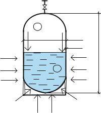
Let us consider the flow of heat to the liquid phase of liquefied gas (Fig. 1).
QT |
tп |
|
QT |
d |
|
|
|
|
|
|
h |
|
tж |
|
QR |
|
QR |
|
QR |
|
Fig. 1. Calculation scheme
cylinder heat exchange tasks
with the environment
67

Russian Journal of Building Construction and Architecture
The impact of the environment on the cylinder is performed in two characteristic zones:
washed gas liquid phase (radial heat);
washed vapor phase of the gas and the liquid phase transferred along the wall (tangential heat).
In order to address the problem, the following assumptions will be used:
heat supply to the cylinder from air is carried out due to natural convective heat transfer [14, 19, 20];
the temperature ofthe cylinder wall isthe same in thicknessand constant:tcm = const;
the temperature of the wall washed by the liquid phase is equal to that of the lique-
fied gas: tcm = tж [6].
The amount of heat supplied to the liquid due to the radial conductivity of the cylinder wall is
QR tв tж Fсм , |
(17) |
where α is the the coefficient of heat transfer from the environment to the wall of the composite cylinder, Watt/m2К.
In turn, the area of the wetted surface of the cylinder, m2, is defined as
|
(d 2 )2 |
|
|
F h (d 2 ) |
|
, |
(18) |
|
|||
см |
4 |
|
|
|
|
|
|
where h is the height of the composite LPG cylinder, m; d is the cylinder diameter, m; is the wall thickness of the composite cylinder, m; is the level of filling the balloon with the liquid phase, proportions.
The heat gain to the liquid phase of the product due to the tangential conductivity of the cylinder wall will thereby have the following form:
Qt |
стPt tв |
tж |
, |
(19) |
|
|
|
where λст is the thermal conductivity coefficient of the cylinder wall participating in tangential heat transfer, Watt/m K; Рt is the perimeter of the surface of the cylinder walls participating in tangential heat transfer, m.
The perimeter of the cylinder surface participating in heat exchange with the vapor phase and transferring heat tangentially is given by the formula:
Рt 2 h d 2 1 . |
(20) |
The total amount of heat inflow to the liquid phase of LPG in the cylinder will be defined as
Q QR Qt . |
(21) |
68
Issue № 3 (51), 2021 |
ISSN 2542-0526 |
Therefore the heat transfer coefficient of the wall of the composite cylinder, referred to its wetted surface, coonsidering expressions (17)––(20), will take the form:
k |
ст Рt |
. |
(22) |
|
|||
|
Fсм |
|
|
Given that the cylinders is installed in the kitchen, in the immediate proximity to the gas stove, the heat transfer from the air to the wall of the composite cylinder will occur due to the natural convection of the air in the room. The heat transfer coefficient from air of a smooth non-metallic surface in this case is given by the ratio [19, 20]:
f (v), |
(23) |
where v is the air velocity near the surface, m/sec.
Considering the regulatory requirements for the velocity of air movement in the premises of kitchens of residential buildings in compliance with SanPiN (СанПиН) 2.1.2645, the value of the heat transfer coefficient will take the value of 6.6 Watt/m2K.
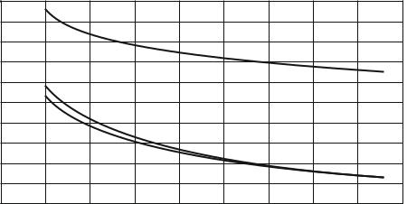
According to expression (22), given (18), (20), (23), calculations were performed to identify the heat transfer coefficient of the wall of a composite LPG cylinder of the two most common standard sizes of cylinders with a volume of 24.5 and 47 liters considering the dynamics of changes in the level of filling with the liquid phase ofthe gas in the range of 10% ≤ φ ≤85 %. The calculation results are shown in the graphs (Fig. 2). To compare, Fig. 2 presents the results of research [8] to identify the heat transfer coefficient of steel 50-liter LPG cylinders.
Values of the coefficients of heat transfer, Watt/m2 2K Значения коэффициента теплопередачи k, Вт/мК
14
3
12
10 2
1
8
7
6
10 |
20 |
30 |
40 |
50 |
60 |
70 |
80 |
90 |
УровеньLevel ofзаполненияfilling of theбаллонаliquefiedсжиженнымgas cylinder,газом% , %
Fig. 2. Values of the heat transfer coefficient of the wall of LPG cylinders:
1 –– composite cylinder with a volume of 24.5 liters; 2 –– a composite cylinder with a volume of 47 liters; 3 –– metal cylinder with a volume of 50 liters
69