

3677
.pdfRussian Journal of Building Construction and Architecture
Fig. 3. Obtaining a shadow projection of wires for identifying the deformations and geometric shape of the surface of a building structure: a) a scheme for identifying the deformations of building structures using the shadow projection method; b) measuring the deflection of the wall on the chemical water purification (CWP) building; 1 is a light source; 2 is the investigated construction; 3 is the wire mesh; 4 is the shadow projection of the mesh
Shadows ca n also be used to define the geometric shape of the investigated surface.Prior to launching the survey, a baseline is split in an accessible place along the structure. The photographing of the building structure is taken from one end of the base, and a light source is installed at the other end.
The image shows the wire 3 and its shadow 4 (Fig. 3). The distance of the points of the surface of the investigated part from the wire is denoted by∆Y'.
Y' |
LY' |
|
l1 Y1 Y' Y1 |
|
LY2 |
|
Y' |
|
|
1 |
|
|
|
1 1 |
1 |
|
. |
(1) |
|
B |
Bf |
Bf |
|
||||||
|
|
|
|
Y1 |
|
||||
If the wire is stretched near the surface of the investigated part, formula (1) can be simplified
Y' |
LY2 |
pY2 |
|
||
1 1 |
|
1 1 |
, |
(2) |
|
|
|
||||
|
Bf |
Bf |
|
||
where l =∆Р1.
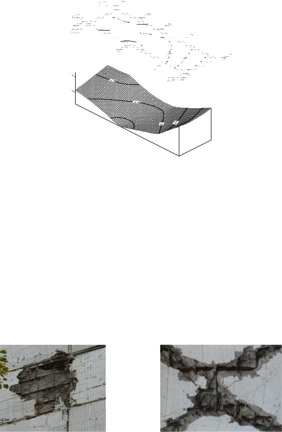
Using the calculated ∆Y', it is possible to construct a surface profile in a given direction or draw horizontals of equal values of ∆Y', as well as make an orthographic projection of the surface of the current vertical displacements of the building structure (Fig. 4).
If, under the action of deformations, the controlled surface has moved from position I to position II (Fig. 1), using formula (2), it can be written
Y'' |
l Y |
2 |
|
p Y2 |
|
|
2 1 |
|
2 1 |
, |
(3) |
||
|
|
|||||
|
Bf |
|
|
Bf |
|
|
In this case, the deformation along the Y-axis of a point on the surface of the structure will be equal to
Y Y'' Y' |
p Y2 |
pY |
2 |
|
pY2 |
|
||
2 1 |
|
1 1 |
|
|
1 |
, |
(4) |
|
|
Bf |
|
|
|||||
|
Bf |
|
|
Bf |
|
|||
where ∆pis the distance in the picture between the shadow images.
30
Issue № 3 (51), 2021 |
ISSN 2542-0526 |
Fig. 4. Orthographic surface projection of current vertical offsets building structure І––ІІ
For identifying deformations, photography is performed twice –– before and after the deformation. In the process of measurements, the starting point for determining ∆p is the count on the wire image.
The advantage of the suggested method of shooting with a shadow projection of the grid is that photography is conducted from one convenient standing point, while it is possible to increase the accuracy of identifying ∆U by increasing the shooting , i.e., the distance between the camera and the light source.
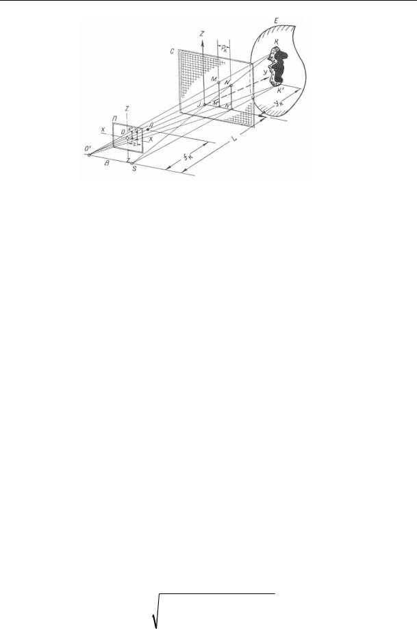
In order to the parameters of chips, irregularities, grooves of individual building structures (Fig. 5) and control their development, the method of stereo-shadow photogrammetry can be used. The scheme of the research principle is shown in Fig. 6.
Fig. 5. Failure of the structure of facing panels
31
Russian Journal of Building Construction and Architecture
Fig. 6. Stereo-shade photogrammetry(general research principles): P –– plane of the photograph; A –– optical center of the camera lens; C –– mesh; E is the object of research. X, Y, Z –– spatial coordinates and their axes;
B –– beam; S –– illuminator; fk is the focal length of the camera; 0—0 '- main optical axis of the camera;
L is the distance from the point of convergence of the rays to the plane of the grid; К — К '–– coordinate points of the object of study; Рk –– parallax of point K; r –– converted in the photograph the value of the parallax point
K to be measured; j is the point of intersection of the main optical axis of the camera with the grid;
N, N' are the projections of coordinate points K and K' on the grid;
Yk is the distance from the coordinate point K' of the research object
For this research, it is necessary to set up a large-format camera on a tripod and use a tacheometer to orient it accurately in space. The optical axis ofthe camera should be oriented strictly perpendicular to the plane ofthe grid which is placed between the camera and the structure.
The camera must be rigidly connected to the base where the illuminator is set up. A grid with an orthogonal filament system is placed in front of the camera at a fixed distance. While illuminating a building structure, the light passes through the mesh and a projection of this mesh is displayed on the surface of the structure. In addition, the shadow pattern of each shadow thread forms the cross-sectional profile of the investigated section of the structure.
In the resulting images, measurements can be made and the spatial coordinates X, Y and Z of the selected points along the profile line can be obtained. Based on the data, it is possible to construct a mathematical model of the geometric parameters of the structure of the studied object along the selected sections. The requirements for the measurement accuracy of Y can be identified based on the well-known formulas (5 and 6).
m |
X |
m |
2 |
|
m |
|
2 |
mf 2 |
|
(5) |
||||
|
Y |
|
|
|
X |
|
|
|
|
|
, |
|||
|
|
|
||||||||||||
X |
|
Y |
|
X |
|
f |
|
|
||||||
|
|
|
|
|
|
|
|
|
|
|
|
|||
32
Issue № 3 (51), 2021 |
ISSN 2542-0526 |
m |
Z |
m |
2 |
|
m |
2 |
|
mf 2 |
. |
(6) |
||||
|
Y |
|
|
Z |
|
|
|
|
||||||
|
|
|
||||||||||||
Z |
|
Y |
|
Z |
|
f |
|
|
||||||
|
|
|
|
|
|
|
|
|
|
|
|
|||
Depending on the operating conditions, the accuracy of measuring the distances mY can be defined as the specified accuracy of determining the deformations m∆X, m∆Z or, the accuracy of measuring the displacements m∆x, m∆z on the images.
In the first case, we will have:
m Y |
m X |
, |
(7) |
||
|
|
|
|||
Y |
|
X |
|
||
|
|
|
|||
In the second case: |
|
|
|
|
|
m Y |
m x |
, |
(8) |
||
|
|||||
Y |
|
x |
|
||
|
|
|
|||
where ∆Х and ∆x are respectively the maximum values of the deformations of the points of the structure and the measured displacements in the image; m∆Х is the error in determining the deformations ∆Х due to the influence of errors in identifying the distances.
The calculated value of m∆X in the formula (7) should be 2––3 times less than the specified one, so that the distance errors do not impact the accuracy of identifying the deformations. Accordingly, the calculated value of m∆Х for the same reason should be 2––3 times less than the measurement accuracy of displacements.
The requirements for the accuracy of determining the focal length of the camera is given by the formula (9): where ∆X and ∆x are the maximum values of the deformations of the points of the structure and the measured displacements in the photograph, respectively; m∆Х is the error in determining the deformations ∆Х, due to the influence of errors in determining the distances.
The calculated value of m∆X in the formula (7) should be 2––3 times less than the specified one, so that the distance errors do not affect the accuracy of determining the deformations. Accordingly, the calculated value of m∆Х for the same reason should be 2––3 times less than the measurement accuracy of displacements.
Requirements for the accuracy of determining the focal length of the camera is given by the formula (9):
|
|
m |
X |
mf |
, |
|
(9) |
|||
|
|
|
|
|||||||
|
|
X |
|
|
|
f |
|
|||
|
|
|
|
|
|
|
|
|||
hence |
|
|
|
|
|
|
|
|
|
|
m |
f |
|
m X |
f |
m x |
f . |
(10) |
|||
X |
|
|||||||||
|
|
|
|
x |
|
|||||
33
Russian Journal of Building Construction and Architecture
So, e.g., at m∆x = 0.002 mm, m∆Х = 0.50 mm; f = 200 mm we will get mf = 0.8 mm.
2. Identifying the deformations of high-rise buildings. Deformation control and executive geodetic survey of high-rise buildings in close-built conditions are often a difficult and timeconsuming task. In this case, a stereophotogrammetric control method can be employed.
Field work in this case does not cause any difficulty and entails standard photographing of the structure from two permanently fixed points and a number of auxiliary geodetic measurements.
The methods of cameral processing of the obtained images can cause a certain degree of complexity.
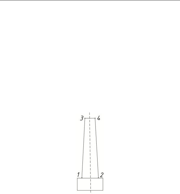
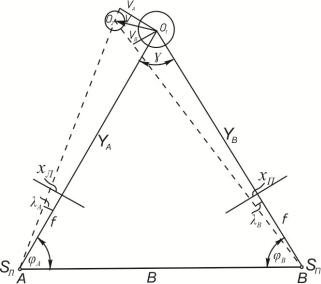
If the structure is depicted in the image symmetrically to the z-axis of the image, by measuring the coordinates of four lateral points 1––4 on a single image (Fig. 7), it is possible to determine the partial rolls of the structure VA and VB (Fig. 8).
Fig. 7. Location of points for identifying the inclination of the chimney
Based on Fig. 7 and 8 we can write:
VA |
x x |
|
x x |
Y |
Y |
' |
xA, |
|
|||||
|
3 |
4 |
|
1 |
2 |
|
A |
|
A |
(11) |
|||
|
2 |
|
2 |
|
|
||||||||
|
|
|
|
|
|
f |
f |
|
|
|
|||
|
|
' |
' |
' |
' |
|
YB |
|
|
' |
|
|
|
VB |
x3 |
x4 |
|
x1 |
x2 |
|
|
YB |
xB , |
(12) |
|||
|
2 |
|
2 |
|
|
||||||||
|
|
|
|
|
|
f |
f |
|
|
|
|||
In this case, the total roll value can be found both graphically and analytically.
While shooting multiple subjects at the same time, their images might appear on the edges of the image resulting in perspective distortions in the image.
34
Issue № 3 (51), 2021 |
ISSN 2542-0526 |
Fig. 8. Identifying the inclination of the chimneywhen it is located in the image symmetricallyto the ZZ axis
In order to exclude a forward-looking error, a correction should be introduced into formulas 11 and 12:
|
|
|
x2x |
|
|
|
||||
x |
|
|
|
|
ср |
|
|
, |
||
|
|
|
|
|
|
|
|
|||
0 |
|
|
|
|
|
|
|
2 |
|
(13) |
|
|
4 f 2 |
1 |
xср |
|
|||||
|
|
|
|
|
|
f |
2 |
|
|
|
|
|
|
|
|
|
|
|
|
||
|
x |
x1 |
x2 |
, |
|
|
||||
|
|
|
|
|
||||||
|
ср |
|
2 |
|
|
|
|
(14) |
||
|
|
|
|
|
|
|
|
|
||
x x1 x2.
Giventhe correction, the originalformula for identifyingthe partialroll(11) willtake the form:
V |
x3 x4 |
x |
|
x1 x2 |
x |
|
VA |
|
x |
x |
x |
x |
|
VA |
|
||||
|
|
|
|
||||||||||||||||
|
2 |
|
0B |
2 |
|
f |
|
|
|
|
|
0В |
cрH |
0H |
f |
||||
A |
|
|
|
|
0H |
cрВ |
|
|
|
|
|
||||||||
|
|
xcрВ xcрH x0B |
x0H |
VA |
|
|
VA |
xA x , |
(15) |
||||||||||
|
|
f |
|
|
|
|
|||||||||||||
|
|
|
|
|
|
|
|
|
|
|
f |
|
|
|
|
|
|||
where δхв , δх0н are corrections for perspective distortion for high and low points of a structure; ∆ δхА is the measured value of the roll of the structure in the image; δх is the correction in the measured declination value.
The mean square error in determining the roll according to formula (15) will be equal to
m2 |
|
|
YA |
2 |
m2 |
|
|
xA |
2 |
m2 . |
(16) |
|
|
|
|
||||||||
VA |
|
|
f |
x |
|
|
f |
YA |
|
||
|
|
|
|
|
|
|
|
|
|
It should be remembered that the accuracy of identifying the partial roll VA is affected by the error in determining the distance YA. The distance can be found in various ways. With a roll
35

Russian Journal of Building Construction and Architecture
∆X = 0.1 –– 0.3 m, it is enough to determine the distance graphically. For large values of the roll, an analytical calculation is required.
While determining the distance from n images
m |
m |
B |
2 |
1.4m |
2 |
(17) |
||||||
Y |
|
|
|
|
|
|
|
|
|
, |
||
|
B |
|
|
|
||||||||
|
|
n |
||||||||||
Y |
|
|
|
|
|
|
||||||
hence the requirement for the accuracy of measuring the basis for various values of the roll is identified:
m |
m |
2 |
1.4m |
2 |
(18) |
|||||
B |
|
|
Y |
|
|
|
|
|
. |
|
|
Y |
|
|
|
||||||
|
|
n |
||||||||
B |
|
|
|
|
|
|||||
Depending on the method ofcontrolling the external orientation elements, the roll ofthe structure can be given by the difference between the coordinates of the upper and lower axes of the structure witha relative root-mean-square error of1/6000 –– 1/16000 ofthe height ofthe structure.
However, it should be remembered that the accuracy of determining the roll might be somewhat reduced in the case of the image of the structure along the edges of the image.
It is sensible to apply the spatial roll to apply the convergent case of shooting at a convergence angle close to 90°. It must also be ensured that the image of the structure is located closer to the central part of the image. While the roll direction is in a plane parallel to the datum, the normal survey should be used. In this case, the roll of the structure can be determined with an error of up to 1/30000 of the height of the structure.
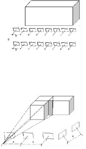
Route and block surveys.
While controlling deformations on extended objects, it is better to perform block or route survey of the object (Fig. 9).
Fig. 9. Route survey of the extended object
36
Issue № 3 (51), 2021 |
ISSN 2542-0526 |
With this type of survey from several stereopairs obtained by means of a normal or equally inclined survey method, the survey should be conducted with the expectation that additional stereopairs have an overlap area of 60 %.
If the object in the image is not completely located in the height, a block survey should be performed involving several strips (Fig. 10). At the same time, several parallel routes are formed, having a lateral overlap of 20––30 % or more. If there is not enough space for installing cameras, shooting can be performed from different heights, e.g., from the ground and from the roof of a building.
Fig. 10. Block surveyof the object
If separate sections of the structure are not displayed on the stereopair, a survey should be performed from additional bases (Fig. 11).
Fig. 11. Shooting of invisible points of the object from additional bases
While processing the results of measurements of the roll increments on site, the above technique for any case of shooting and as well as all of the formulas provided can be used.
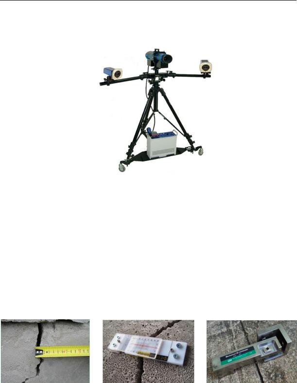
In practice, for this type of work, it is convenient to use stereophotogrammetric setups consisting of two cameras fixed on a rigid base (Fig. 12). For each type of work, the basis can
37
Russian Journal of Building Construction and Architecture
change or remain unchanged. Shooting is performed simultaneously with two cameras. The optical axes of the cameras are parallel to each other and perpendicular to the base.
Fig. 12. Stereophotogrammetric installation for control of deformations of building structures
[Source URL: https://sapr.ru/article/24694 (reference date 18.04.21)]
3. Methods for measuring the dynamics of sedimentary cracks. In addition to identifying the magnitude of deformations using photography, an accurate documentary control of the dynamics of the development of sedimentary cracks can be performed.
Traditionally, crack propagation is monitored by means of measuring with the simplest instruments (Fig. 13) and using beacons of various designs. The depth of the cracks is determined using needles and wire probes.
а) |
b) |
c) |
Fig. 13. Traditional methods of controlling crack development: a) a tape measure; b) an electronic fracture tester «Mayak ZI-2U»
[Source URL: здание-инфо.рф/2012/03/(reference date 18.04.21)] c) 3D crack measurer 6310 [Source URL: https://monsol.ru/mechanicheskiy-3d-treshinomer-6310/(reference date 18.04.21)]
38
Issue № 3 (51), 2021 |
ISSN 2542-0526 |
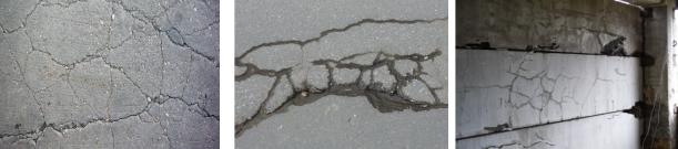
However, in the presence of a large number of cracks of various depths and directions (Fig. 14), as well as in the case of hard-to-reach cracks, the use of traditional methods is not always possible.
Fig. 14. A network of numerous vertical and horizontal cracks of various depths and directions which
are difficult to control bymeans of traditional methods
In these cases, metric photography can also be employed to measure cracks. Shooting cracks can be performed with a conventional amateur camera. In order to identify the size of cracks, it is necessary to know the scale of the image in the image which is determined according to the size of standard parts (brickwork, ruler). The accuracy of measuring the direction and size of cracks can be increased if there are marking points along the edges of the crack. To eliminate perspective distortions, one should strive to install the camera parallel to the plane of the structure under study.
To determine the increments of cracks, it is necessary to repeat the survey from the same point so that the images of subsequent cycles have a scale equal to the scale of the first image. To do this, it is necessary to securely fix the photographing points.
The crack increment can be found by stereoscopic measurement of the displacement in the image ∆x, (∆z), as is done with the photogrammetric method for determining deformations with subsequent calculations using formulas (19) and (20).
|
' |
|
|
x' |
x |
|
x |
|
||||||||
X X |
|
X Y |
|
|
|
|
Y |
|
|
Y |
|
|
|
xM, |
(19) |
|
|
|
|
|
|
|
|
|
|
||||||||
|
|
|
|
f |
f |
|
f |
|
||||||||
|
' |
|
z |
' |
|
|
|
z |
z |
|
||||||
Z Z |
|
Z Y |
|
|
|
|
Y |
|
|
|
Y |
|
|
|
zM, |
(20) |
|
|
f |
|
|
|
|
|
|
|
|
||||||
|
|
|
|
|
|
|
|
f |
|
f |
|
|||||
where X, Z and X', Z' are the coordinates of the points in the image before and after the deformations.
4. Features of processing ground images when monitoring the state of building struc-
tures. Stereopairs and single ground images of building structures are processed according to
39