

3677
.pdfRussian Journal of Building Construction and Architecture
The coefficient Пx is identified experimentally and Пx can be given by the formula shown
below (68). According to [6, 7] and given (64), the shear angle in the lower zone 2—3 will be:
|
|
|
|
ctg |
|
|
|
tg |
|
|
|
sin |
|
cos |
|
|
|
sx |
|
sx |
ctg |
|
|
sy sy |
tg |
|
|
2Nxy |
|
, (66) |
||
xy |
sx |
3 |
sy |
3 |
bt |
3 |
3 |
|
E |
|
|
3 |
E |
|
3 |
2aE |
|
|||||||||||||||
|
|
|
|
|
|
|
|
|
|
s |
|
|
|
s |
|
|
Пх |
|||||||||||||||
|
|
|
|
|
|
|
|
|
|
|
|
|
|
|
|
|
|
|
|
|
|
|
|
|
|
|
|
b |
||||
where Es is the modulus of reinforcement deformation in the plastic stage of reinforcement deformation, everywhere Es is replaced by Esvs, where vs is the secant modulus given by the dependencies [8].
8. Identifying the deformations in the upper compression zone of concrete. The deformation of concrete in the compressed zone is given by the dependence:
|
|
b |
|
Nb |
, |
(67) |
|
|
|||||
b |
|
|
|
|
|
|
|
|
Eb b |
|
Fс Eb b |
|
|
where Fс is the area of the concrete of the compressed zone given by the formula (12); b is the coefficient of the development of plastic deformations in the concrete of the compressed
zone. Based on [8], the coefficient b is given by the formula: |
|
b ˆb 0 ˆb 1 1 2 |
(68) |
(for the ascending branch of the diagram, the sign <+> is taken, and for the descending branch, the sign <–>), where
|
|
|
|
–– the level of the main stresses in concrete (positive value) where is the level of the main |
|||
stresses in concrete (positive value): |
|
||
|
|
|
|
b |
, |
(69) |
|
|
|||
ˆb
where the current main stresses b given by the formula (11); ˆb are the stresses at the top of
the diagram |
|
ˆ |
R |
; ˆ |
is the coefficient of change of the secant modulus at the top of |
|||||||||||
|
b |
b,ser |
b |
|
|
|
|
|
|
|
|
|
|
|
|
|
the diagram (positive value): |
|
|
|
|
|
|
|
|
|
|
|
|
||||
|
|
|
|
|
|
|
|
ˆ |
ˆ |
|
|
, |
|
(70) |
||
|
|
|
|
|
|
|
|
|
b |
|
|
|
||||
|
|
|
|
|
|
|
|
E ˆ |
|
|
||||||
|
|
|
|
|
|
|
|
b |
|
|
|
|
||||
|
|
|
|
|
|
|
|
|
|
|
b |
b |
|
|
|
|
|
|
|
|
|
|
|
|
|
|
B |
2 |
|
|
|
|
|
|
|
|
|
|
|
|
|
|
|
|
|
|
||||
|
|
|
|
|
|
|
1 |
0.8 0.15 |
|
|
|
B / 60 0.2 B |
|
|||
|
|
|
|
|
B |
|
|
|
|
|
|
|||||
|
|
|
ˆ |
|
|
|
10000 |
|
|
, |
(71) |
|||||
|
|
|
|
|
|
|
|
|
|
|
|
|||||
|
|
|
b |
|
Eb |
|
0.12 1.03B / 60 |
|
||||||||
|
|
|
|
|
|
|
||||||||||
here B is the concrete class corresponding to Rb ser; λ is the dimensionless coefficient depending on the concrete type (for heavy and fine-grained concrete λ = 1); vb is the initial co-
20
Issue № 3 (51), 2021 |
ISSN 2542-0526 |
efficient of change of the secant module; ω is the coefficient characterizing the curvature of the diagram.
For the ascending branch of the diagram depending on (71):
|
0 |
1; |
2 2.5ˆb1; |
(72) |
|
for the descending branch of the diagram: |
|
|
|
|
|
0 |
2.05ˆb , |
1.95ˆb 0.138. |
(73) |
||
The above formulas refer to the case of compression of the upper concrete zone (zones 1––4)
|
|
|
|
|
|
|
|
|
|
|
|
|
|
|
0 , but there have not been |
|||||||||
at b 0. In case the main stresses are tensile ones b |
bt |
|||||||||||||||||||||||
any cracks yet, the diagram of concrete tensile |
|
|
|
|
|
should be given by the formulas |
||||||||||||||||||
bt bt |
||||||||||||||||||||||||
(58)—(64) where где , |
ˆ , |
, |
ˆ , |
, |
ˆ |
, ˆ |
are replaced by , |
ˆ , |
, |
ˆ , |
, |
ˆ , |
||||||||||||
|
b |
b |
b |
b |
b |
b |
|
b |
|
|
|
|
|
|
|
|
|
|
bt |
bt |
bt |
bt |
bt |
bt |
t respectively: |
|
|
|
|
|
|
|
|
|
|
|
|
|
|
|
|
|
|
|
|
|
|
|
|
|
|
|
|
|
ˆ |
, |
|
|
|
|
|
|
|
|
|
|
|
|
|
|
(74) |
|||
|
|
|
|
t |
bt |
|
bt |
|
|
|
|
|
|
|
|
|
|
|
|
|
|
|
|
|
where ˆ , |
ˆ are the stresses and relative deformations at the top of the tensile diagram for |
|||||||||||||||||||||||
bt |
bt |
|
|
|
|
|
|
|
|
|
|
|
|
|
|
|
|
|
|
|
|
|
|
|
the normative diagram: |
|
|
|
|
|
|
|
|
|
|
|
|
|
|
|
|
|
|
|
|
|
|
|
|
|
|
|
|
ˆ |
R |
|
|
|
; |
ˆ |
|
|
|
ˆ |
|
|
, |
|
|
|
|
(75) |
||
|
|
|
|
|
|
bt |
|
bt |
|
|
|
|
||||||||||||
|
|
|
|
|
|
|
|
|
|
|
|
|||||||||||||
|
|
|
|
|
bt |
bt.ser |
|
btq |
|
|
|
|
E ˆ |
bt |
|
|
|
|
|
|
|
|||
|
|
|
|
|
|
|
|
|
|
|
|
|
|
|
b |
|
|
|
|
|
|
|
|
|
where |
|
|
|
|
|
|
|
|
|
|
|
|
|
|
|
|
|
|
|
|
|
|
|
|
|
|
|
ˆ |
0.55 0.15R |
|
/ R |
|
/ |
btq |
. |
|
|
|
|
(76) |
|||||||||
|
|
|
bt |
|
|
|
|
|
bt.ser |
|
0bt |
|
|
|
|
|
|
|
|
|
||||
Here Rbt = 2.5 МPа; γbtq is the coefficient considering the influence of the deformation gradients for crack resistance:
btq b 0.007 . (77)
Here 0.9 b 2 5 h
h hэ , hэ 0.3 m is some exemplary height (the values btq were identified for the bending elements, for the torsion bending a specification btq might be needed. The normal by and tangential xy stresses in the cocnrete of the compressed zone acting normally and along the line 7—10 (Fig. 4) will be:
|
|
N |
by Nycb1tg с |
|
|
|
|
|
|
Nyx |
|
|
|
|
|
N |
by Nyxb1tg с |
|
|
|
|||||
by |
|
|
Fcy |
|
|
|
XT b |
; xy |
|
XT . |
(78) |
|
Accordingly, the normal and shear relative deformations will be:
|
|
|
|
|
N |
by |
N |
btg |
с |
|
|
|
2N |
1 |
|
||
|
|
by |
|
|
|
yx 1 |
|
|
|
|
yx |
b |
|
|
|||
by |
Eb b |
|
|
|
|
XT bEb b |
|
, |
xy |
|
XT Eb b |
, |
(79) |
||||
21

Russian Journal of Building Construction and Architecture
where b is the coefficient of the transverse deformations of the concrete.
b |
b |
|
|
b |
b |
1 ; |
(80) |
|
ˆ |
|
|
ˆ |
b is the initial coefficient of the transverse deformations of the concrete b 0.175 ; ˆb is
the coefficient corresponding to the top of the diagram:
|
|
|
|
|
|
|
|
b |
|
|
|
|
b |
|
|
|
b |
|
; |
|
(81) |
|
|
|
|
|
|
|
ˆ |
|
1 3 ˆ |
|
|
||||||||||
|
|
by is given by the formula (35) and |
Nyx |
|
|
|
|||||||||||||||
N |
|
by the formula (6). The curvature of the element |
|||||||||||||||||||
and relative deformations 0y at the level of the |
y axis. |
|
|
|
|
||||||||||||||||
After identifying sy using the formula (59) and |
|
using the formula (79) , the curvature of |
|||||||||||||||||||
by |
|||||||||||||||||||||
the element and the relative deformations 0y |
|
can be identified: |
|
||||||||||||||||||
1 |
|
sy |
|
|
|
|
|
|
|
|
|
|
|
|
|
||||||
|
- by |
|
, |
|
|
|
|
|
|
|
|||||||||||
|
|
|
|
|
|
|
|
|
|
|
|
|
|
|
|
|
|
|
|||
|
|
|
y |
|
|
Z1 |
|
|
|
|
|
|
|
|
|
|
|||||
|
|
|
|
|
|
|
|
|
|
|
|
|
|
|
|
|
|
(82) |
|||
|
|
|
|
|
|
|
sy |
Z |
1 |
|
0.h 0.5 h |
|
|||||||||
|
|
|
|
|
|
|
|
|
|
|
|
|
1 |
|
|
by 1 |
|
|
|||
|
|
0y |
|
|
|
|
|
|
|
|
|
|
|
|
|
|
|
. |
|
||
|
|
|
|
|
|
|
|
|
|
Z1 |
|
|
|
|
|
||||||
|
|
|
|
|
|
|
|
|
|
|
|
|
|
|
|
|
|
|
|
||
|
|
|
|
|
|
|
|
|
|
|
|
|
|
M, |
T based on the formulas(59) and (79), we |
||||||
Expressing sy and by using the commonefforts |
|||||||||||||||||||||
willget the ultimate dependencies for identifying the curvature ofthe relative deformations 0y .
9. Shear angles of the vertical walls of the element. Let us consider the element 7––8––11
(Fig. 3, 4). The average relative deformations of this element along the axis |
y will be: |
|||||||||||
|
|
|
sy 1 |
|
|
|
|
|
||||
y 1 |
|
|
|
|
by |
|
, |
(83) |
||||
|
|
|
|
|
2 |
|
||||||
|
|
|
|
|
|
|
|
|
|
|
||
where εsy(1), εby are given by the formulas (56), (79). |
|
|
|
|
||||||||
The stresses σsy(1) in the vertical rods of the clamps are |
|
|||||||||||
|
|
|
|
|
|
|
sz 1 |
|
|
|
|
|
sz 1 |
|
|
|
N |
|
|
. |
(84) |
||||
|
|
|
||||||||||
f |
sw |
Z tg |
||||||||||
|
|
|
|
|
|
1 |
1 |
|
|
|||
Accordingly, the relative deformations of the vertical rods of the stirrups in the range 7––8––9 will be:
|
|
sz 1 |
sz 2 |
|
sz 1 |
sz 1 |
|
, |
(85) |
||||||
|
|
|
Es |
|
|
|
|
||||||||
|
|
|
|
|
|
|
|
|
|
|
|
|
|
||
where |
|
|
|
|
|
|
|
|
|
|
|
|
|
|
|
|
sz 1 |
|
sz 2 |
|
1 0,75 |
|
crc |
|
|
; |
|
||||
sl |
|
sz i |
|
|
|||||||||||
|
|
|
|
|
|
|
|
||||||||
|
|
|
|
|
|
|
|
|
|
|
|
|
|||
22
Issue № 3 (51), 2021 |
ISSN 2542-0526 |
sz 1 is given by the formula (57) where sy i is replaced by sz 1 , in the plastic stage of the
reinforcement deformation s is replaced by s s . The formulas (61) — (66) still hold true
where xy is replaced by Zy , Nyx |
byNZy 1 , 3 |
by 1, in the indices |
x byZ 1 . As a result, |
|||||||||||||||||||||||||||||||||||
|
yZ 1 sZ 1 ctg 1 |
|
|
|
|
|
|
|
|
|
|
|
|
|
|
|
2NyZ 1 |
|
|
|
, |
(86) |
||||||||||||||||
|
|
|
|
|
|
|
|
|
2aE |
|
|
|
|
|
|
|||||||||||||||||||||||
|
bytg 1 |
|
пyZ 1 |
ПZ 1 |
||||||||||||||||||||||||||||||||||
|
|
|
|
|
|
|
|
|
|
|
|
|
|
|
|
|
|
|
|
|
|
|
|
|
|
|
|
|
b |
|
|
|
|
|||||
where similarly to the formula (65): |
|
|
|
|
|
|
|
|
|
|
|
|
|
|
|
|
|
|
|
|
|
|
|
|
|
|
|
|
|
|
|
|
|
|
||||
|
|
|
|
|
|
|
П |
|
ПZ 1 |
|
yZ 1 |
, |
|
|
|
|
|
|
|
|
|
|
|
|
|
|||||||||||||
|
|
|
ПZ 1 |
|
|
|
|
|
|
|
|
|
|
|
|
|
|
|
|
|
|
(87) |
||||||||||||||||
|
|
|
П 0.8, |
|
yZ 1 xy |
|
|
|
|
|
|
|
|
|
|
|
|
|||||||||||||||||||||
|
|
|
|
. |
|
|
|
|
|
|
|
|
|
|
|
|||||||||||||||||||||||
|
|
|
|
|
|
|
|
|
|
|
|
|
|
|
|
|
|
|
|
|
|
|
|
|
|
|
|
|
|
|
|
|
|
|
|
|||
Using the formula (15), we get the expression yz 1 |
|
into the function of T . Let us look at the |
||||||||||||||||||||||||||||||||||||
element 3—4—13. The stresses sZ 2 , deformations Z 2 |
and shear angles yZ 2 |
are given by |
||||||||||||||||||||||||||||||||||||
the formulas (83) — (87), y 1 , |
sy 1 , |
sz 1 , |
|
|
sz 1 , |
|
|
|
|
|
|
sz 1 , |
ПyZ 1 , |
|
ПyZ 1 , |
yZ 1 are re- |
||||||||||||||||||||||
N |
|
1, |
|
|
||||||||||||||||||||||||||||||||||
|
|
sz 2 , |
|
sz 2 , |
|
ПyZ 2 |
|
, ПyZ 1 , yZ 1 |
|
|
|
|||||||||||||||||||||||||||
placed by y 2 , sy 2 , sz 2 , N |
2 , |
|
|
|
respectively. As a result, |
|||||||||||||||||||||||||||||||||
|
|
|
|
|
|
|
|
|
|
|
|
|
sy |
2 |
|
|
|
|
|
|
|
|
|
|
|
|
|
|||||||||||
|
|
|
|
|
|
y 2 |
|
|
|
|
|
|
|
|
|
by |
, |
|
|
|
|
|
|
|
|
|
||||||||||||
|
|
|
|
|
|
|
|
|
|
|
|
|
2 |
|
|
|
|
|
|
|
|
|
|
|
|
|
||||||||||||
|
|
|
|
|
|
|
|
|
|
|
|
|
|
|
|
|
|
|
|
|
|
|
|
|
|
|
|
|
|
|
|
|
|
|
|
|
||
|
|
|
|
|
|
|
|
|
|
|
|
|
|
|
|
|
|
|
|
|
|
|
|
|
|
|
|
|
|
|
|
|
|
|
|
|
|
|
|
|
|
|
|
|
|
|
|
|
|
|
|
|
|
|
|
Nsz 2 |
|
|
|
|
|
|
|
|
|
|
|
||||||||||
|
|
|
|
|
|
|
|
|
|
|
|
|
|
|
|
|
|
|
|
|
|
|
|
|
|
|
(88) |
|||||||||||
|
|
|
|
|
|
|
sz |
2 |
|
|
|
|
|
|
|
|
|
|
|
|
|
|
|
, |
|
|
|
|
|
|
|
|
||||||
|
|
|
|
|
|
|
fswZ1tg 2 |
|
|
|
|
|
|
|
|
|||||||||||||||||||||||
|
|
|
|
|
|
|
|
|
|
|
|
|
|
|
|
|
|
|
|
|
|
|
||||||||||||||||
|
|
|
|
|
|
|
|
|
|
|
|
|
sz 2 sz 2 |
|
|
|
|
|
|
|
|
|
|
|
|
|
||||||||||||
|
|
|
|
|
|
|
sz 2 |
|
, |
|
|
|
|
|
|
|
|
|
||||||||||||||||||||
|
|
|
|
|
|
|
|
|
|
|
|
|
|
E |
|
|
|
|
|
|
|
|
|
|
|
|
|
|
|
|
|
|
||||||
|
|
|
|
|
|
|
|
|
|
|
|
|
|
|
|
|
|
|
|
|
s |
|
|
|
|
|
|
|
|
|
|
|
|
|
|
|
|
|
|
|
|
yz 2 |
sz 2 ctg 2 |
y 2 tg 2 |
|
|
2Nyz 2 |
|
, |
(89) |
|||||||||||||||||||||||||||
|
|
|
2aE |
ПZ 2 |
|
|||||||||||||||||||||||||||||||||
|
|
|
|
|
|
|
|
|
|
|
|
|
|
|
|
|
|
|
|
|
|
|
|
|
|
|
|
|
|
|
|
b |
|
|
|
|
||
where ПZ 2 |
П ПZ 2 yZ 2 , П |
0.8, yZ 2 xy . Based on the dependencies (15) the shear |
||||||||||||||||||||||||||||||||||||
angle yZ 2 |
is expressed using the values T . |
|
|
|
|
|
|
|
|
|
|
|
|
|
|
|
|
|
|
|
|
|
|
|
|
|||||||||||||
The torque angle , based on [6, 7] is identified using the values of the shear angles ( xy of the lower surface according to (66), xy of the upper compressed zone according to (79),
yZ 1 |
of the first vertical wall according to (86) and yZ 2 of the second vertical wall accor- |
|||||
ding to (89)) according to the formula |
|
|
|
|
||
|
|
b1 xy |
xy Z1 yZ 1 |
yZ 2 |
. |
(90) |
|
|
2b1Z1 |
|
|||
|
|
|
|
|
|
|
23

Russian Journal of Building Construction and Architecture
Based on the dependencies (6)—(8), (13), (15), (35), (55), (66) the torque angle is ex-
pressed in the function of M and T.
10. Additional remarks on the design of complex stressed reinforced concrete bars of
solid cross-section in torsion with bending. The above dependences are designed so that the wall thickness of the element is not limited and makes it possible to switch to a solid section. It should only be noted that in elements of a solid section, according to [15], after the formation of cracks, part of the torque T2 can be perceived by some still solid core of the section, which remains in the element following the cracking, and part of the moment T1 is perceived by the section with a crack. Moreover, in the above formulas, T is replaced by T1, according to the study by T. P. Chistova:
|
|
T |
4 |
|
||
T T T ; |
T T 1 0.3 |
|
cr |
|
, |
(91) |
|
||||||
1 2 |
1 |
T |
|
|
||
|
|
|
|
|
||
|
|
|
|
|
|
|
where Tcr is the torque moment at the moment of cracking; T is the current moment (T > T). In bending with torsion, the effect of the concrete core in [15] should be taken into account only in the presence of spiral cracks developing along the entire contour. In the presence of concrete in the compressed zone without cracks, the effect of the concrete core can be neglected, assuming T2 = 0.
Conclusions
1.An updated block design model of the complex resistance of reinforced concrete structures of a box section, experiencing the combined action of bending and torque moments after the formation of spatial cracks, which, on the one hand, is limited by a calculated rectangular contour, on the other hand, is a spatial surface with planes inclined to the edges of the structure, has been designed. The stresses in the concrete of the compressed zone and the height of the compressed concrete, the stresses in the clamps, the deformations in the compressed zone, in the rods of the longitudinal and transverse reinforcement, the curvature of the element and the angle of its twisting are identified using the equations of statics in the sections intersected by the faces of the spatial crack and element with cracks.
2.In the suggested design model, a variant is considered when out of three external influences: torque T, bending M moments, and transverse force Q during torsion with bending, the greatest influence on the stress-strain of the structure is exerted by the moments T and M. The moment is reduced to the action of the flow of tangential forces along a rectangular contour.
3.The suggested analytical model for calculating design parameters can be used in designing a wide class of reinforced concrete structures of buildings and structures from ordinary and
24
Issue № 3 (51), 2021 |
ISSN 2542-0526 |
high-strength concrete and fiber-reinforced concrete under the considered complex stress in
these structures.
References
1.Arzamastsev S. A., Rodevich V. V. K raschetu zhelezobetonnykh elementov na izgib s krucheniem [To the calculation of reinforced concrete elements for bending with torsion]. Izvestiya vuzov. Stroitel'stvo, 2015, no. 9, pp. 99—109.
2.Dem'yanov A. I., Sal'nikov A. S., Kolchunov Vl. I. Eksperimental'nye issledovaniya zhelezobetonnykh konstruktsii pri kruchenii s izgibom i analiz ikh rezul'tatov [Experimental studies of reinforced concrete structures under torsion with bending and analysis of their results]. Stroitel'stvo i rekon-struktsiya, 2017, no. 4 (72), pp. 17—26.
3.Dem'yanov A. I., Kolchunov Vl. I., Pokusaev A. A. Eksperimental'nye issledovaniya deformirovaniya zhelezobetonnykh konstruktsii pri kruchenii s izgibom [Experimental study of deformation of reinforced concrete structures in torsion with bending]. Stroitel'naya mekhanika inzhener-nykh konstruktsii i sooruzhenii, 2017, no. 6, pp. 37—44.
4.Karpenko N. I. [determination of the deformations of the core elements of reinforced concrete box cracked torsional]. Referativnyi sb. TsINISA: Mezhotraslevye voprosy stroitel'-stva. «Otechestvennyi opyt» [Abstract collection of TSINIS: Intersectoral issues of construction. "Domestic experience"], 1970, no. 10.
5.Karpenko N. I., Elagin E. G. Deformatsii zhelezobetonnykh trubchatykh elementov, podvergnutykh krucheniyu posle obrazovaniya treshchin [Deformation of reinforced concrete tubular members subjected to torsion after cracking]. Beton i zhelezobeton, 1970, no. 3, pp. 3—12.
6.Karpenko N. I. [To the calculation of deformation of reinforced concrete members with cracks under bending with torsion-received]. Sb. NIIZhB: Teoriya zhelezobetona, posvyashchennom 75-letiyu so dnya rozhdeniya A. A. Gvozdeva [Proc. NIIZHB: Theory of reinforced concrete, devoted to the 75 anniversary since the birth of A. A. Gvozdev]. Moscow, Stroiizdat Publ., 1972, pp. 50—59.
7.Karpenko N. I. Teoriya deformirovaniya zhelezobetona s treshchinami [The Theory of deformation of reinforced concrete with cracks]. Moscow, Stroiizdat Publ., 1976. 208 p.
8.Karpenko N. I. Obshchie modeli mekhaniki zhelezobetona [General models of reinforced concrete mechanics]. Moscow, Stroiizdat Publ., 1996. 410 p.
9.Kasaev D. Kh. Prochnost' betonnykh i treshchinostoikost' zhelezobetonnykh elementov pryamougol'nogo secheniya pri kruchenii i izgibe s krucheniem [Strength of concrete and crack resistance of reinforced concrete elements of rectangular cross-section during torsion and bending with torsion]. Beton i zhelezobeton v tret'em tysyacheletii, 2000, pp. 164—171.
10.Kolchunov V. I., Kolchunov Vl. I., Fedorova N. V. Deformatsionnye modeli zhelezobetona pri osobykh vozdeistviyakh [Deformation models of reinforced concrete under special influences]. Promyshlennoe i grazhdanskoe stroitel'stvo, 2018, no. 8, pp. 54—60.
11.Kolchunov Vl. I., Fedorov V. S. Ponyatiinaya ierarkhiya modelei v teorii soprotivleniya stroitel'nykh konstruk-tsii [Conceptual hierarchy of models in the theory of resistance of building structures]. Promyshlennoe i grazhdanskoe stroitel'stvo, 2020, no. 8, pp. 16—23. doi: 10.33622/0869-7019.2020.08.16-23.
25

Russian Journal of Building Construction and Architecture
12.Travush V. I., Karpenko N. I., Kolchunov V. I., Kaprielov S. S., Dem'yanov A. I., Konorev A. V. Rezul'taty eksperimental'nykh issledovanii konstruktsii kvadratnogo i korobchatogo sechenii iz vysokoprochnogo betona pri kruchenii s izgibom [The Results of experimental studies of the structures of square and box-like cross-sections of high-strength concrete in torsion with bending]. Stroitel'stvo i rekonstruktsiya, 2018, no. 6—80, pp. 32—43.
13.Travush V. I., Karpenko N. I., Kolchunov V. I., Kaprielov S. S., Dem'yanov A. I., Bulkin S. A., Moskovtseva V. S. Rezul'taty eksperimental'nykh issledovanii slozhnonapryazhennykh balok kruglogo poperechnogo secheniya iz vysokoprochnogo fibrozhelezobetona [Results of experimental studies of complexstressed beams of circular cross-section made of high-strength fibro-reinforced concrete]. Stroitel'naya mekhanika inzhenernykh konst-ruktsii i sooruzhenii, 2020, no. 4, pp. 290—297.
14.Travush V. I., Karpenko N. I., Kolchunov V. I., Kaprielov S. S., Dem'yanov A. I., Konorev A. V. Osnovnye rezul'taty eksperimental'nykh issledovanii zhelezobetonnykh konstruk-tsii iz vysokoprochnogo betona V100 kruglogo i kol'tsevogo sechenii pri kruchenii s izgibom [The main results of experimental studies of reinforced concrete structures made of high-strength concrete B100 of round and annular sections during torsion with bending]. Stroitel'naya mekhanika in-zhenernykh konstruktsii i sooruzhenii, 2019, no. 1, pp. 51—61.
15.Chistova T. P. [Experimental study of deformations of ordinaryreinforced concrete elements of box-shaped and solid rectangular cross-section under pure torsion]. Prochnost' i zhest-kost' zhelezobetonnykh konstruktsii
[Strength and stiffness of reinforced concrete structures]. Moscow, Stroiizdat Publ., 1971.
16.Klein G., Lucier G., Rizkalla S., Zia P., Gleich H. Torsion simplified: a failure plane model for desigh of spandrel beams. ACI Concrete International Journal, 2012, pp. 1—19.
17.Kalkan I., Kartal S. Torsional Rigidities of Reinforced Concrete Beams Subjected to Elastic Lateral Torsional Buckling. International Journal of Civil and Environmental Engineering, 2017, no. 7, pp. 969—972.
18.Karpenko N. I., Kolchunov Vl. I., Kolchunov V. I., Travush V. I. Calculated model of a complex-stressed reinforced concrete element under torsion with bending. International Journal for Computational Civil and Structural Engineering, 2021, vol. 17, no. 1, pp. 34—47.
19.Travush V. I., Karpenko N. I., Kolchunov V. I., Kaprielov S. S., Demyanov A. I., Bulkin S. A., Moskovtseva V. S. Results of experimental studies of high-strength fiber reinforced concrete beams with round cross-sections under combined bending and torsion. Structural Mechanics of Engineering Constructions and Buildings, 2020, vol. 16, no. 4, pp. 290—297.
26

Issue № 3 (51), 2021 |
ISSN 2542-0526 |
DOI 10.36622/VSTU.2021.51.3.002
UDC 528.48
B. A. Popov1, N. B. Khakhulina2, Yu. S. Netrebina3
APPLICATION OF PHOTOGRAMMETRIC METHODS FOR GEOTECHNICAL
MONITORING OF EMERGENCY BUILDINGS AND STRUCTURES
Voronezh State Technical University 1, 2, 3
Russia, Voronezh
1PhD in Agriculture, Assoc. Prof. of the Dept. of Cadastre of Real Estate, Land Management and Geodesy, tel.: +7 (473) 271-50-72, e-mail: b.p.geo@yandex.ru
2PhD in Engineering, Assoc. Prof. of the Dept. of Cadastre of Real Estate, Land Management and Geodesy, tel.: +7 (473) 271-50-72, e-mail: hahulina@mail.ru
3PhD in Geography, Assoc. Prof. of the Dept. of Cadastre of Real Estate, Land Management and Geodesy, tel.: +7 (473) 271-50-72, e-mail: juliya_net @ mail.ru @ mail.ru
Statement of the problem. One of the relevant scientific and technical issues for improving the state-of-the-art and advanced monitoring methods is alarm construction (including in the minds of ordinaryminds) with the emergence of uncompromising objects, and the future of unfinished control. It is quite common that conditions arise when it is not possible to perform a full-fledged monitoring of certain types of deformations of building structures bymeans of traditional methods. It is required to develop universal, superior and manual methods for the control of different geometric parameters of structures for taking timely measures to ensure the stability and stability of the structure and enabling thetransition ofthe structurein theinterconnection of the roboticmill as well.
Results. All of the considered methods of statistics of the ways to control the output and have been revised based on the maintenance and repair of the conserved Voronezh nuclear power plant for heat supply.
Conclusions. The methods of calculating deformations and the quality of the preparation of alarm constructions for metric photography allowance to carry out repeated monitoring of the technical mill with thenecessaryaccuracy.
Keywords: photogrammetry, deformation, roll, settlements, monitoring.
Introduction. According to the analysis of scientific literature and the experience of construction organizations, while monitoring the stress-strain of building structures, it might be necessary to work in very cramped conditions when due to a small distance to the object, it is not possible to set up a geodetic device or image sharpness on the device [2, 17, 9].
© Popov B. A., Khakhulina N. B., Netrebina Yu. S., 2021
27

Russian Journal of Building Construction and Architecture
At the same time, modern research in the field of deformation control commonly focuses only on measuring settlements, rolls and horizontal displacements of bases and foundations, and not on controlling the geometric parameters of individual building structures [1, 3––5, 7––11, 13––16, 18, 20].
Meanwhile, according to SP (СП) 22.13330.2011 (clause 5.6.4) and SP 126.13330.2012 (clause 8.6), in the process of monitoring a structure under construction, in addition to settlements, rolls and displacements, torsions, deflections of structures, their technical condition and other parameters should be monitored whose composition depends on the aim and construction conditions of the premises. This has become particularly relevant in the recent years as the world is building unique structures on a growing scale that are distinguished by nonstandard structural solutions, the use of new construction technologies and building materials whose behavior under the influence of various loads and aggressive environmental influences has not yet been sufficiently studied.
It should also be remembered that there is a large number of unfinished and suspended construction projects in the country. While controlling deformations in such objects, in the absolute majority of cases, traditional measurements are curtailed by the tightness of operating conditions, the uneven effect of various meteorological factors (illumination, temperature, refraction, turbulent air flows) and deformation of structures and soil in the immediate proximity of the structures.
All of these caused a number of significant shortcomings that are found in the system for monitoring the safety of construction sites. Firstly, in modern construction practice, there is commonly no constant monitoring of the technical condition of the object and the neighboring territory. Only a selective examination of the technical condition of individual objects is commonly carried out. Secondly, up to now, no criteria have been developed for a comprehensive assessment of the state of an object in each period of time. Thirdly, the construction customer often lacks an understanding of the need for such continuous integrated monitoring, which causes a lack of funding for this type of work.
Under such conditions, it is impossible to conduct a full-fledged monitoring of certain types of deformations of building structures by means of traditional methods. It is required to develop universal, reliable and convenient methods for monitoring various geometric parameters of the structure for taking timely measures to ensure the stability and durability of the structure in order to exclude the transition ofthe structure to a partially operable or emergency state.
Therefore one of the urgent scientific and technical problems in construction is currrently the improvement of methods for monitoring the state of building structures (including in cramped
28
Issue № 3 (51), 2021 |
ISSN 2542-0526 |
working conditions) during the construction of unique structures and objects of unfinished construction, ensuring reliable control of their quality, stability and safety.
Thus the authors are seeking to make use of the capabilities of metric photography when observing the deformations of building structures, individual nodes and parts located in hard-to- reach places or confined working conditions.
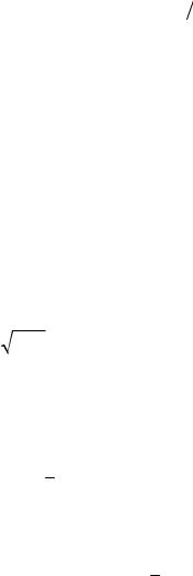
1. Control of deformations and quality of manufacturing of building structures. While determining deformations and controlling the manufacture of building structures along the Y-axis (Fig. 1, 2) in confined working conditions, the photogrammetric method with a sha-dow projectionofa grid ofwires stretched in front ofthe investigated surface can be employed (Fig. 3).
Fig. 1. Scheme for identifying deformations of building structures bymeans of the photogrammetric method (location of axes in ground photogrammetric survey)
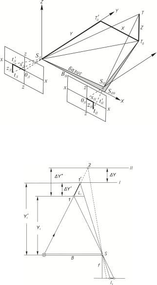
Fig. 2. Identifying thedeformationsbymeansofthephotogrammetricmethod with shadowprojection ofwiremesh:
1 is a wire; I––II is the position of the planes of the structures; 1 / and 2 is the shadow from the wire on the planes of the structure I and II
29