

3677
.pdfRussian Journal of Building Construction and Architecture
The hydraulic resistance of the «wet» chamber of the air cooler turned out to be 20 % higher than that calculated based on (11).
Pa
m/sec
Fig. 4. Graph of the dependence of the hydraulicresistance of the air cooler chambers on the velocityof the major air flow and the mass of the nozzle:
 - М = 3 kg;
 - М = 2,5 kg;
 - М = 2
 kg; is the calculation based on (11)
4. Conclusion. The efficiency of supply ventilation in hot weather can be increased by using an evaporative air cooler. The article gives a detailed description of the design of the cooler developed by the authors where a fluidized layer in the field of centrifugal forces serves as a nozzle.
Theoretical and experimental studies of such an air cooler have been conducted. Analytical relations were obtained in order to identify the time of movement of the nozzle in the «wet» chamber of the device, the temperature of the cooled air and the temperature of the nozzle in any section of the circulation circuit. Empirical relations are obtained for the efficiency coefficient of the cooler and its hydraulic resistance.
The above dependences serve as a foundation for developing a technique of design calculation of similar air coolers.
References
1.Barannikov N. M., Agapov Yu. N., Barakov A. V. Regenerativnyi teploobmennik s kipyashchim sloem [Regenerative heat exchanger with a fluidized bed], 1983, no. 3321506. 2 p.
2.Agapov Yu. N., Barakov A. V., Ostashev A. E. [Selection and justification of the heat and mass transfer surface of the evaporative air cooling apparatus]. Sb. nauch. tr “Teploenergetika” [Proc. “Tep-loenergetika”]. Voronezh, VGTU Publ., 1995, pp. 133–142.
50
Issue № 3 (51), 2021 |
ISSN 2542-0526 |
3.Barakov A. V., Dubanin V. Yu., Prutskikh D. A. Issledovanie gidrodinamiki regeneratora s dispersnoi nasadkoi [Investigation of hydrodynamics of a regenerator with a dispersed nozzle]. Energosberezhenie i vodopodgotovka, 2009, no. 1, pp. 47––48.
4.Barakov A. V., Dubanin V. Yu., Prutskikh D. A., Naumov A. M. Issledovanie vozdukhookhladitelya kosvenno-isparitel'nogo tipa s dispersnoi nasadkoi [Research of an air cooler of an indirect-evaporative type with a dispersed nozzle]. Promyshlennaya energetika, 2010, no. 11, pp. 37––40.
5.Barakov A.V., Dubanin V. Yu., Kozhukhov N. N., Prutskikh D. A. Utilizatsiya teploty ventilyatsionnykh vybrosov promyshlennykh zdanii [Utilization of heat of ventilation emissions of industrial buildings]. Nauchnyi zhurnal stroitel'stva i arkhitektury, 2019, no. 4 (56), pp. 46–56.
6.Barakov A.V., Dubanin V. Yu., Kozhukhov N. N., Prutskikh D. A. Modelirovanie teplomassoobmena v vozdukhookhladitele kosvenno-isparitel'nogo tipa [Modeling of heat and mass transfer in an air cooler of an indirectevaporativetype]. Nauchnyi vestnikVoronezhskogo GASU. Stroitel'stvoi arkhitektura, 2015,no. 4 (40), pp. 28––33.
7.Boev S.V., Agapov Yu. N., Stognei V. G. Raspredelenie temperatur teplonositelei pri trekhfaznom psevdoozhizhenii [Temperature distribution of heat carriers in three-phase fluidization]. Vestnik Voronezhskogo gosudarstvennogo tekhnicheskogo universiteta, 2011, vol. 7, no. 1, pp. 221––223.
8.Ivanov O. P. Vybor oborudovaniya dlya utilizatsii tepla i kholoda v sistemakh konditsionirovaniya vozdukha [The choice of equipment for heat and cold utilization in air conditioning systems]. Kholodil'naya tekhnika, 1986, no. 6, pp. 12––15.
9.Kokorin O. Ya. Energosberezhenie v sistemakh otopleniya, ventilyatsii, konditsionirovaniya [Energysaving in heating, ventilation, air conditioning systems]. Moscow, ASV publ., 2013. 256 p.
10.Koroleva N. A., Tarabanov M. G. Energosberezhenie za schet kosvennogo isparitel'nogo okhlazhdeniya v sistemakh venti-lyatsii i konditsionirovaniya vozdukha [Energy saving due to indirect evaporative cooling in ventilation and air conditioning systems]. Energosberezhenie i vodopodgotovka, 2015, no. 2 (94), pp. 39––42.
11.Naumov A. M. Modelirovanie teplomassoobmena v vozdukhookhladitele kosvenno-isparitel'nogo tipa. Diss. kand. tekhn. nauk [Modeling of heat and mass transfer in an air cooler of an indirect evaporative type. Dr. eng. sci. diss.]. Voronezh, 2010. 110 p.
12.Agapov Yu. N., Barakov A. V., Naumov A. M. Vozdukhookhladitel' [Air cooler]. Patent RF, 2006, no. 2006114868.
13.Prutskikh D. A. Gidrodinamika i teploobmen v regeneratore s dispersnoi nasadkoi. Diss. kand. tekh. nauk [Hydrodynamics and heat transfer in a regenerator with a dispersed nozzle. Cand. eng. sci. diss.]. Voronezh, 2009. 108 p.
14.Stepanenko M. N., Shelginskii A. Ya. Ispol'zovanie teploty ventilyatsionnykh vybrosov v sistemakh ventilyatsii zdanii [The use of heat of ventilation emissions in building ventilation systems]. Nadezhnost' i bezopasnost' energetiki, 2014, no. 2 (25), pp. 42––45.
15.Tabakova A. S., Novikova O. V. [Improving the efficiency of heat consumption of a building when using modern ventilation systems]. Materialy nauchnogo foruma s mezhdunarodnym uchastiem “Nedelya nauki SPbPU” [Proc. “SPbPU Science Week”], 2015, pp. 135––138.
16.Comino F., Ruiz de Adana M., Peci F. Energy saving potential of a hybrid HVAC system with a desiccant wheel activated at low temperatures and an indirect evaporative cooler in handling air in buildings with high latent loads. Applied Thermal Engineering, 2018, vol. 131, pp. 412––427.
51

Russian Journal of Building Construction and Architecture
17.Duan Z., Zhan C., Zhang X., Mustafa M., Zhao X., Alimohammadisagvand B., Hasan A. Indirect evaporative cooling: Past, present and future potentials. Renewable and Sustainable Energy Reviews, 2012, vol. 16, iss. 9, pp. 6823––6850.
18.Kamel E., Memari A. M. State-of-the-Art Review of Energy Smart Homes. Journal of architectural engineering, 2019, vol. 25, iss. 1, pp. 1––26.
19.Rashad M., Khordehgah N., Żabnieńska-Góra A., Ahmad L., Jouhara H. The utilisation of useful ambient energy in residential dwellings to improve thermal comfort and reduce energy consumption. International Journal of Thermofluids, 2021, vol. 9, pp. 125––135.
52

Issue № 3 (51), 2021 |
ISSN 2542-0526 |
DOI 10.36622/VSTU.2021.51.3.004 UDC 536.24
L. A. Kushchev1, V. A. Uvarov2, N. Yu. Savvin3, S. V. Chuikin4
INTENSIFIED PLATE HEAT EXCHANGE DEVICE IN HEAT SUPPLY SYSTEMS
OFTHE HOUSING AND COMMUNAL SERVICES OFTHE RUSSIAN FEDERATION
Belgorod State Technological University Named after V. G. Shukhov,
Civil Engineering Institute 1, 4
Russia, Belgorod
Voronezh State Technical University 2, 3, 4
Russia, Voronezh
1D. Sc. inEngineering,Prof. oftheDept.ofHeat andGas Supply and Ventilation, e-mail:leonidkuskev@gmail.com
2D. Sc. in Engineering, Prof. of the Dept. of Heat and Gas Supply and Ventilation, e-mail: n-savvin@mail.com
3PhD student of the Dept. of Heat and Gas Supply and Ventilation, e-mail: n-savvin@mail.ru
4PhD in Engineering,Assoc. Prof. of the Dept. of Heatand GasSupply andOiland Gas, e-mail: ser.chu@mail.ru
Statement of the problem. The problem of intensification of heat exchange processes in a plate heat exchanger on the basis of the HH№ 02 heat exchanger of the Ridan company is discussed. It is essential to carry out an analysis of the existing methods of intensification of heat exchange processes in plate devices according to the results of the analysis to choose the most promising method of intensification of heat exchange process and based on it to develop a patent-protected design of a heat exchange plate. Laboratory tests of the intensified plate heat exchanger with increased turbulence of the coolant are performed. The results of thermal tests on a specialized laboratoryinstallation of the resulting and the serial heat exchanger are presented.
Results. The results of the comparison of experimental studies of the intensified plate heat exchanger with the increased turbulence of the heat carrier and the serial plate heat exchanger of identical heat power are shown. The graphs ofdependence ofthe heat transfer coefficient, which is the major characteristicoftheoperation ofheat exchangeequipment,on theaveragetemperaturepressurearedesigned.
Conclusions. As a result of the laboratory tests in the specialized laboratory of BSTU named after V. G. Shukhov and research at the Voronezh State Technical University established a rise in the heat transfer coefficient due to the increased turbulence of the coolant flow, which causes a decrease in metal consumption and reduces the cost of heat exchange equipment.
Keywords: plate heat exchanger, corrugated surface, experimental studies, heat transfer coefficient, intensification of heat exchange process, turbulence.
Introduction. The territory of the Russian Federation is made up by five climatic zones with the heating period lasting from 72 to 365 days according to a zone [10].
Thus in order to create comfortable working and living conditions, heat supply systems are used in housing and communal services. In Russia, the most common one is the centralized
© Kushchev L. A., Uvarov V. A., Savvin N. Yu., Chuikin S. V., 2021
53

Russian Journal of Building Construction and Architecture
heat supply as with this type of heat supply guarantees low fuel consumption and operating costs. The advantage is the low degree of air pollution which improves the sanitary condition of settlements [5].
However, in the second half of the 20th century and in the early 21st century, decentralized, autonomous and individual heat supply systems are becoming more common. This is partly due to the extensive cottage construction both in the Russian Federation and in the developed countries of the world [13].
In a decentralized heat supply system, the heat source and the heat sink are practically combined, i.e., the heating network is either very small or absent. Such a heat supply can be individual with separate heating devices used in each room [11]. Decentralized heating differs from centralized heating by local distribution of the produced heat. Small boiler houses, hot water boilers, stove and electric heating, including modern heat pump setups [15] are used as a heat source.
Heat exchange equipment is currently used in heat supply systems, the use of plate devices is particularly advantangeous. They became a real breakthrough in the energy sector of housing and communal services. This is due to the high technical and economic performance of the plate heat exchange equipment. Thus the problem of modernizing and improving the technical characteristics of such equipment is extremely relevant.
The objective of the study is to develop a plate design for intensifying heat exchange processes in plate devices to increase the heat transfer coefficient K, W / (m2 K).
1. Intensification of heat exchange processes in heat exchange equipment. In compliance with the requirements for heat exchangers, in production for solving problems of heat supply and the choice of equipment, several types of apparatus structures and thus schemes for the movement of heat carriers are selected. Heat carriers with the necessary thermal and hydraulic calculations for the designed heat exchangers are chosen depending on the operating conditions. To conclude, an economic calculation is made taking into consideration the capital investment, profitability, maintenance costs, etc. [14].
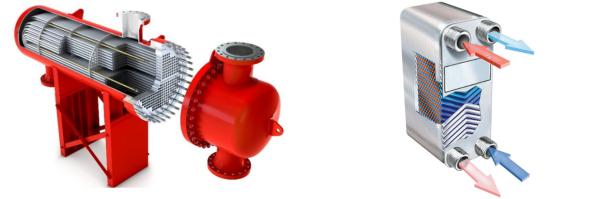
In heat supply systems, the most common shell-and-tube and plate heat exchangers as shown in Fig. 1.
In line with the Soviet and Russian experience, shell-and-tube heat exchangers in heat supply systems for housing and communal services are reliable and cost-effective. However, the major disadvantage of this type of equipment is the low heat transfer coefficient K, W / (m2 K), in comparison with plate heat exchangers [3, 4].
54
Issue № 3 (51), 2021 |
ISSN 2542-0526 |
а) |
b) |
Fig. 1. Heat exchange equipment:
a) shell-and-tube heat exchanger; b) plate heat exchanger
The use of plate heat exchangers in heat supply systems for housing and communal services leads to an increase in the heat transfer coefficient K, W / (m2 K) as well as that in the efficiency of a substation due to a decrease in the amount of subcooling and a drop in labor costs during repair and maintenance. Such advantages are accounted for by small overall dimensions with a high value of the heat transfer coefficient K, W / (m2 K). Thus an increase in the energy efficiency of technological equipment of heating networks causes a significant economic effect [12, 22].
It is important to note that there are several classifications of ways to improve the designs of plate heat exchangers. Among the known directions of modernization of the design of plate heat exchangers, the major ones can be pinpointed:
changing the geometry of the heat exchange surface;
the use of mechanical turbulators;
the use of external physical fields;
the use of solid particles in the coolant. Let us look at these areas in more detail.
Changing the geometry of the heat transfer surface for lamellar devices consists in that of the shape of the plate surface. Therefore A. Yu. Maskinskaya at the Moscow Power Engineering Institute developed a plate with spherical dimples [7]. The result of the study was the identification of dependencies suitable for calculating characteristics in heat power facilities given the influence of the depth of the dimples, the height of the channel and the degree of turbulence characteristic of the developed currents.
55

Russian Journal of Building Construction and Architecture
The work by the Italian specialists R. Morreti and M. Ereira [23] on the use of plates with different corrugation heights is of interest. This made it possible to increase the heat transfer by 10 %, however, with such a modification, an increase in pressure losses is observed at high speeds.
The impact on the flow of mechanical turbulators is created, as noted by A. P. Zegzhda, by adding deflectors of various geometric shapes [2], which contribute to the rational separation of coolant flows to reduce the hydraulic resistance H, m, and increase the heat transfer coefficient K, W / (m2 K).
The use of external physical fields, particularly acoustic vibrations, made it possible to increase the values of the average heat transfer coefficients only at an intensity of vibrations above 140 dB, which is dangerous for human hearing [8]. The use of ultrasonic vibrations increased the efficiency of the heat transfer process by 5 times, however, according to studies in degassed water, a slight intensification was noted [25].
In order to intensify heat transfer, solid particles are used in the coolant, e.g., ferrimagnetic particles are introduced moving under the action ofa rotating magnetic field [1, 20, 24]. According to the official representatives of Alfa Laval in Russia, the heat transfer coefficient increases by 40 %, but filters must be set up at the inlet and outlet of the apparatus. Investigations were conducted related to the use of a heating circuit coolant, which included a nanofluid, which is a suspension of copper and zinc nanoparticles [6]. At the same time, themaximum –– 1.5 times –– the heat transfer went up with the use of copper. This method of intensification is only possible in the chemical, petrochemical and food industries, and for them to be employed in in heat supply, specialized boiler and pumping equipment will have to be used [16, 19, 26].
Note that active methods of intensifying the heat exchange process require the use of thirdparty devices causing an increase in the energy consumption and thereby an increase in the maintenance and repair costs.
An alternative option is the use of passive methods acting on the boundary layer due to the application of ribbing, the use of rough surfaces, swirlers and other developed heat exchange surfaces [17, 21]. Complex methods of intensification of the heat exchange process are also utilized combining several methods in one technological process, e.g., a combination of rough surfaces and swirlers [18, 20].
A feature of the device of plate heat exchangers is the design and shape of the heat exchange surface and channels for the operating environment. The heat exchange surface is formed from separate plates, and the channels for the operating environment have a slot-like shape. The ope-
56
Issue № 3 (51), 2021 |
ISSN 2542-0526 |
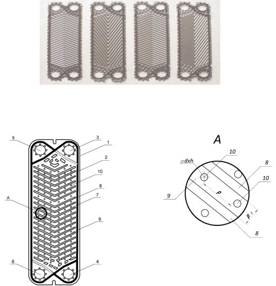
rating environments move at the heat exchange surface in a thin layer, which contributes to the intensification ofthe heat transfer process. The shapesofthe plates and their surface profiles are shown in Fig. 2.
Fig. 2. Shapes of the plates and profiles of the surfaces
а) |
b) |
Fig. 3. Heat exchanger plate:
a) general view of the plate; b) viewA; 1 –– metal plate serving as the basis of the product; 2 –– a sealing gasket; 3 –– outlet of the heated circuit; 4 –– inlet of the heated circuit; 5 ––heating circuit inlet; 6 –– outlet of the heating circuit; 7 –– the main heat exchange part; 8 –– corrugation (corrugation); 9 –– area between adjacent corrugations; 10 –– technological recess of a spherical shape; d is the diameter of the recess, m; h is theheight of therecess, m; p is the step of the indentations, m; p2 –– distance between adjacent corrugations, m
In order to intensify the heat transfer, an original design of an intensified plate heat exchanger with modified corrugated plates [9] is set forth whose design feature is the corrugated heat
57

Russian Journal of Building Construction and Architecture
exchange plates shown in Fig. 3.The developed plates have spherical grooves located according to a linear law, i.e., betweenadjacent corrugations of the main heat exchange part.
2. Experimental heat engineering studies of an intensified plate heat exchanger in a
laboratory setup. Conducting field experimental studies is necessary to establish the effect on the efficiency of the intensified plate heat exchanger with the increased turbulization of the coolant of the following factors:
1)the flow rate of the heating agent in the heating and heating circuits, Ggr; Gng, m3/h;
2)the values of the liquid temperature at the inlet to the heating and heated circuits of the intensified plate heat exchanger, t1gr, t1ng, 0С.
Experimental studies were performed in a specialized laboratory of BSTU named after V. G. Shukhov at the laboratory setup "Independent Heating System of a Residential Building". At the same time, the safety requirements were observed. The aim of the experiment is to compare the heat and power and hydrodynamic characteristics of two devices:
serial plate heat exchanger designed in compliance with GOST (ГОСТ) 15518-87;
original intensified plate heat exchanger with corrugated plates containing spherical technological recesses.
Table
Physical and chemical characteristics of coolants
№ |
Parameter |
|
Value |
|
|
|
|
|
|
Heating contour |
|
|
|
|
|
1 |
Density, kg/m3 |
|
998 |
|
|
|
|
2 |
Rigidity, mmole/l |
|
8 |
|
|
|
|
3 |
Turbidity, cm |
|
27—29 |
|
|
|
|
4 |
Specific heat capacity, kJ/(kg К) |
|
4.2 |
|
|
|
|
5 |
Maximum temperature, 0С |
|
85 |
|
|
|
|
|
|
Heated contour |
|
|
|
|
|
6 |
Density, kg/m3 |
|
998 |
|
|
|
|
7 |
Rigidity, mmole/l |
|
8 |
|
|
|
|
8 |
Turbidity, cm |
|
27—29 |
|
|
|
|
9 |
Specific heat capacity, kJ/(kg К) |
|
4.2 |
|
|
|
|
10 |
Minimum temperature, 0С |
|
20 |
|
|
|
|
General view of the laboratory installation "Independent heating system of a residential
building" is shown in Fig. four.
58

Issue № 3 (51), 2021 |
ISSN 2542-0526 |
An intensified plate heat exchanger, the main element of which is a modified corrugated plate with spherical depressions located according to a linear law [9], between adjacent corrugations, is the central element of the laboratory setup.
The table shows the physical and chemical characteristics of the coolants used in the experiments.
Fig. 4. Laboratorysetup "Independent Heating System of a Residential Building":
1 ––hot water electric boiler "Rusnit"; 2 –– heat calculator "Vzlet TSRV-042"; 3 –– Vzlet flow meters; 4 –– manometers; 5 –– circulation pump Grundfoss UPS 32-40;
6 –– intensified plate heat exchanger; 7 —heater
The piping of the experimental setup is made with polymer pipelines with a diameter of
Dy = 15; twenty; 25; 32 mm. Shut-off valves (ball valves) and control valves (valves) of corresponding diameters were set up.
59