

Russian Journal of Building Construction and Architecture
.pdfRUSSIAN JOURNAL
OF BUILDING
CONSTRUCTION AND ARCHITECTURE

The journal is indexed/abstracted in:
Web of Science Core Collection
(Emerging Sources Citation Index)
(Thomson Reuters), USA
Ulrich's Periodicals Directory
(Bowker), USA
DOAJ
(Lund University), Sweden
Academic Search Complete
(EBSCO), USA
SOCOLAR
(China Educational Publications Import
and Export Corporation –– CEPIEC),
China
Google Scholar
(Google), USA
E-Library
(ООО «РУНЭБ»), Russia
J-Gate
(Informatics Ltd), India
ISSN 2542-0526
RUSSIAN JOURNAL
OF BUILDING CONSTRUCTION
AND ARCHITECTURE
N 3 (51)
BUILDING STRUCTURES, BUILDINGS AND CONSTRUCTIONS
BASES AND FOUNDATIONS, UNDERGROUND STRUCTURES
HEAT AND GAS SUPPLY, VENTILATION, AIR CONDITIONING, GAS SUPPLY AND ILLUMINATION
BUILDING MATERIALS AND PRODUCTS
TECHNOLOGY AND ORGANIZATION OF CONSTRUCTION
DESIGNING AND CONSTRUCTION OF ROADS, SUBWAYS, AIRFIELDS, BRIDGES AND TRANSPORT TUNNELS
BUILDING MECHANICS
THEORY AND HISTORY OF ARCHITECTURE, RESTORATION AND RECONSTRUCTION OF HISTORICAL
AND ARCHITECTURAL HERITAGE
ARCHITECTURE OF BUILDINGS AND STRUCTURES. CREATIVE CONCEPTIONS OF ARCHITECTURAL ACTIVITY
CITY PLANNING, PLANNING OF VILLAGE SETTLEMENTS
Voronezh 2021

Russian Journal
of Building Construction and Architecture
Periodical scientific edition
Published since 2009 |
Comes out 4 times per annum |
|
|
|
|
|
|
Founder and publisher: Voronezh State Technical University.
The territoryof distribution — Russian Federation.
The articles are reviewed and processed with the program ANTIPLAGIARISM. This publication cannot be reprinted without the prior permission of the publisher, references are obligatory.
Previous name: «Scientific Herald of the Voronezh State University of Architecture and Civil Engineering. Construction and Architecture».
EDITORIAL BOARD
Editor-in-Chief: Melkumov V. N., D. Sc. in Engineering, Prof.,
Voronezh State Technical University
Boldyrev А.М., Corresponding Member of the Russian Academy |
Osipova N.N., D. Sc. in Engineering, Yury Gagarin Saratov State |
of Architecture and Engineering Science, D.Sc. in Engineering, |
Technical University, Russia |
Prof., Voronezh State Technical University, Russia |
Panibratov Yu. P., Academician of RAABS, Saint Petersburg State |
Bondarev B. А., D. Sc. in Engineering, Prof., Lipetsk State Tech- |
University of Architecture and Civil Engineering, Russia |
nical University, Russia |
Podolsky Vl.P., D. Sc. in Engineering, Prof., Voronezh State Tech- |
Gagarin V. G., Corresponding Member of RAABS, Moscow State |
nical University, Russia (Dep. of the Editor-in-Chief) |
University ofCivil Engineering, Russia |
Suleymanov А.М.,D. Sc. in Engineering, Prof., Kazan State Univer- |
Gelfond А. L., Corresponding Member of the Russian Academy of |
sity of Architecture and Engineering, Russia |
Architecture and Construction Science, D. Sc. in Architecture, |
Fyedorov V. S., Academician of RAABS, Moscow State Universi- |
Nizhniy Novgorod State University of Architecture and Construc- |
ty of Railway Engineering, Russia |
tion, Russia |
Fedosov S. V., Academician of RAABS, Moscow State University |
Enin A. Ye., PhD in Architecture, Prof., Voronezh State Technical |
ofCivil Engineering, Russia |
University, Russia |
Chernyshov Ye. M., Academician of RAABS, Voronezh State |
Karpenko N. I., Academician of RAABS, Research Institute of |
Technical University, Russia |
Building Physics (NIISF RAABS), Russia |
Shubenkov М. V., Academician of the Russian Academy of Archi- |
Kirsanov М.N., D.Sc. in Physics and Mathematics, Professor |
tecture and Construction Science, D. Sc. in Architecture, Prof., |
(National Research University “Moscow Power |
Моscow Institute of Architecture (State Academy), Russia |
Engineering Institute”) |
Asanowicz Alexander, Prof., Dr. of Sn., Technical University of |
Kolchunov V. I., Academician of RAABS, Southwest State Uni- |
Bialystok, Poland |
versity, Kursk, Russia |
Figovsky Oleg L., Prof., Dr. of Sn., Member of EAS, Israel |
Ledenyev V. I., D. Sc. in Engineering, Prof., Tambov State Tech- |
Korsun V. I., D. Sc. in Engineering, Prof., The Donbas National |
nical University, Russia |
Academy ofCivil Engineering and Architecture, Ukraine |
Lyahovich L. S., Academician of RAABS, Tomsk State University |
Nguyen Van Thinh, Prof., Dr. of Sn., Hanoi University of Archi- |
of Architecture and Building, Russia |
tecture, Vietnam |
Mailyan L. R., D. Sc. in Engineering, Prof., Don State Technical |
|
University, Rostov, Russia |
|
Editor: Kotlyarova E. S. Translator: Litvinova O. A. Executive secretary: Aralov E. S.
Publication date 20.07.2021. Format 60×84 1/8. Conventional printed sheets 15. Circulation 500 copies. Order 124. Number of the certificate of registration of the media ПИ № ФС 77-67855
Issued bythe Federal Service for Supervision of Communications, Information Technology, and Mass Media (Roskomnadzor)
Priceis subject to change
THE ADDRESS of EDITORIAL AND THE PUBLISHER OFFICE:
room2230,84 20-letiya Oktyabrya str., Voronezh, 394006, Russian Federation Tel./fax: (473)2-774-006; e-mail: vestnik_vgasu@mail.ru
Published in Printing Office of Voronezh State Technical University 84 20-letiya Oktyabrya str., Voronezh, 394006, Russian Federation
© Voronezh State Technical University, 2021
Issue № 3 (51), 2021 |
ISSN 2542-0526 |
CONTENTS |
|
BUILDING STRUCTURES, BUILDINGS AND CONSTRUCTIONS.................................................. |
7 |
Karpenko N. I., Kolchunov Vl. I., Travush V. I. |
|
Calculation Model of a Complex Stress Reinforced Concrete Element |
|
of a Boxed Section During Torsion With Bending.................................................................. |
7 |
Popov B. A., Khakhulina N. B., Netrebina Yu. S. |
|
Application of Photogrammetric Methods for Geotechnical Monitoring |
|
of Emergency Buildings and Structures................................................................................ |
27 |
HEAT AND GAS SUPPLY, VENTILATION, AIR CONDITIONING, |
|
GAS SUPPLY AND ILLUMINATION......................................................................................... |
44 |
Barakov A. V., Dubanin V. Yu., Prutskikh D. A., Nadeev A. A. |
|
Development of an Evaporating Type Air Cooler for Ventilation Systems............................ |
44 |
Kushchev L. A., Uvarov V. A., Savvin N. Yu., Chuikin S. V. |
|
Intensified Plate Heat Exchange Device in Heat Supply Systems ofthe Housing |
|
and CommunalServicesofthe Russian Federation........................................................................ |
53 |
Osipova N. N., Grishin B. M. |
|
Modeling of Operating Modes Gas Composite Cylinders ..................................................... |
63 |
Popov V. M., Barakov A. V., Kuznetsov S. N. |
|
Emergency Ventilation of Clean Rooms............................................................................... |
75 |
DESIGNING AND CONSTRUCTION OF ROADS, SUBWAYS, AIRFIELDS,BRIDGES |
|
AND TRANSPORT TUNNELS.................................................................................................. |
83 |
Volkov V. V., Kozlov V. A., Melkumov V. N. |
|
Experimental Studies of Wearing and Tearing of Asphalt Concrete Surfacing |
|
under the Action of Water Pressure in Micropores................................................................ |
83 |
Shchegoleva N. V., Stolyarov V. V., Kochetkov A. V. |
|
The Procedure of Analysis, Assessment and Risk Reduction of Vehicle Collisions |
|
on a Multi-Lane Road.................................................................................................................... |
93 |
5

Russian Journal of Building Construction and Architecture
BUILDING MECHANICS ...................................................................................................... |
104 |
KirsanovM. N. |
|
Spectrum of Own Frequencies of a Spatial Surfacing Girder............................................... |
104 |
CITY PLANNING, PLANNING OF VILLAGE SETTLEMENTS.................................................. |
114 |
Kapustin P. V., Gavrilov A. I. |
|
Problems of Analysis of Design and Research Methods |
|
of Interaction with the Urban Environment......................................................................... |
114 |
INSTRUCTIONS TO AUTHORS.............................................................................................. |
128 |
6

Issue № 3 (51), 2021 |
ISSN 2542-0526 |
BUILDING STRUCTURES, BUILDINGS AND CONSTRUCTIONS
DOI 10.36622/VSTU.2021.51.3.001
UDC 624.012.45
N. I. Karpenko1, Vl. I. Kolchunov2, V. I. Travush3
CALCULATION MODEL OF A COMPLEX STRESS REINFORCED CONCRETE
ELEMENT OF A BOXED SECTION DURING TORSION WITH BENDING
Research Institute of Structural Physics (NIISF) 1, 2, 3
Russia, Moscow
Southwestern State University (SWU) 2
Russia, Kursk
1D. Sc. in Engineering, Prof., Head of Lab., RAASN Academician, e-mail: niisf_lab9@mail.ru
2D. Sc. in Engineering, Prof., Prof. of the Dept. of Unique Buildings and Structures, Major Researcher, RAASN Academician, e-mail: vlik52@mail.ru
3D. Sc. in Engineering, Prof., Major Researcher, RAASN Academician, e-mail: travush@mail.ru
Statement of the problem. Based on the analysis of domestic and foreign scientific publications and guidelines, it is found that the known deformation models for the calculation of complex tensile reinforced concrete elements during torsional bending are quite conditional. Therefore the article considers the solution of the problem of designing a computational model of a reinforced concrete element during torsion with bending in the post-crack stage, which most fully accounts for the specifics of crack formation, deformation and destruction of such elements. The case is considered for when among all possible external influences the action of torques and bending moments has the greatest influence on the stress-strain.
Results. Using the equations of statics and physical ratios of reinforced concrete, the calculated parameters are identified such as stresses in concrete of compressed zone, height of compressed concrete, stresses in clamps, deformations in concrete and reinforcement, curvature and torsion angle of reinforced concrete element.
Conclusions. The obtained analytical dependences were tested by means of numerical calculation of the reinforced concrete strapping crossbar of the outer contour of a residential building of box section of high-strength concrete. The suggested deformation model can be employed in the design of a wide class of reinforced concrete structures working on torsional bending.
Keywords: reinforced concrete, design model, deformation, complex resistance, torsion with bending, cracks.
Introduction. Despite reinforced concrete structures undergoing a complex stress state –– torsion with bending being relatively common in the practice of design and construction, methods for calculating the strength of such structures examined in scientific publications (e.g., [1, 9, 16,
© Karpenko N. I., Kolchunov Vl. I., Travush V. I., 2021
7

Russian Journal of Building Construction and Architecture
17], etc.) and those used in the guidelines of different countries are not sufficiently rigorous. So, outdated models ofthe girder analogy are still inuse in the EU regulations.
In the domestic guidelines and regulations of the CIS countries, the section method is traditionally employed, which is very conditional when applied to the complex stress. Besides, in the above studies, the solution of problems of strength in bending with torsion is mainly discussed. A model for calculating the angles of twisting and curvatures in reinforced concrete elements in bending with torsion (deformation model) was set forth in [4—6]. In this case, an approach was used with the selection of the design contour of the cross section which is intersected by a spiral crack or its part. A more general model of the mechanics of cracked reinforced concrete in a volumetric stress was presented in the fundamental monograph [8]. Finite element models are currently increasingly used in studies of the complex resistance of reinforced concrete structures. They make it possible to obtain acceptable solutions while calculating in a linearly elastic formulation, as well as in a nonlinear formulation when the given physical-mechanical and stiffness characteristics are used. At the same time, according to experimental [2, 3, 12—14, 19] and numerical studies [9, 10, 18], physical modeling of the crack formation process itself is required based on the general methodology for solving the problem of rigidity, crack resistance and strength of reinforced concrete [11, 18], and the development of the design scheme itself by considering a number of new effects of deformation. This is what makes the study timely and relevant.
The aim of the work is to design a compact and, at the same time, a more general design model of a complexly stressed reinforced concrete box-section element experiencing the combined action of bending M and torque T moments in the stage after the formation of spatial cracks considering the shape of the cross-section, the spatial nature of the cracks, the stress state in longitudinal and transverse rods, as well as in the concrete ofthe compressed zone.
1. Design model of a complex stressed reinforced concrete moment. In order to design a computational model, the approach [6, 7] is used with the allocation of the computational contour of the most stressed spatial cross-section.
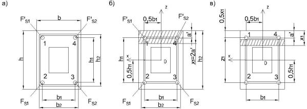
The cross-section of a box-shaped element with section h×b is reinforced with two longitudinal reinforcement bars in a tensioned zone with a total area of 2Fs and in a compression zone with a total area of 2Fs'. The distance between the rods is h1 and b1 (Fig. 1b). The transverse reinforcement is bordered byclosed clamps with the area of the rods Fsw and the pitch Usw0, h1 and b1 are the dimensions of the clamps.
In the design model, the clamps are transferred to the level of longitudinal reinforcement (Fig. 1b) with a reduced pitch Usw, where
8
Issue № 3 (51), 2021 |
ISSN 2542-0526 |
|
Usw Usw0 |
b1 |
h1 |
|
|||||
|
|
|
|
. |
(1) |
||||
|
b2 |
h2 |
|||||||
The reduced running area of the clamps will be |
|
|
|
||||||
F |
F |
/U |
|
F |
b2 h2 |
(2) |
|||
|
|
|
|
. |
|||||
|
|
h1 Usw0 |
|||||||
sw |
sw |
|
w |
sw b1 |
|
||||
Fig. 1 shows two cases.
In the first case, this is the height of the compressed zone:
XT 2a , |
(3) |
where a' is the distance from the upper surface of the section to the center of gravity of the reinforcement in the compressed zone. In this case, the section height is taken equal to h1.
In the second case XT > 2a', with the height being taken equal to Z1.
Let us look at a more general second case.
a) |
b) |
c) |
Fig. 1. Cross-sectional box diagram (a)
with the allocation of calculated contours 1––2––3––4 (b) according to a particular scheme,
(c)–– according to the general scheme
2.Identifying the shear force flows. The transition to the first case is performed by replacing
Z1 with h1. Let us select from the box-shaped section the calculated box-shaped element of size b1 × Z1 (Fig. 2) where Z1 is the distance from the tensioned reinforcement 2Fs to the center of gravity of the concrete in the compressed zone
Z1 h1 a 0.5XT . |
(4) |
In this case, the reinforcement of the compressed zone is transferred to the new line 1––4 to the safety margin. Also, the linear reduced area of the clamps is somewhat specified
9