

Scientific Herald of the Voronezh State University of Architecture and Civil Engineering Construction and Architecture
.pdfSCIENTIFIC HERALD
OF THE VORONEZH STATE UNIVERSITY
OF ARCHITECTURE AND CIVIL ENGINEERING
CONSTRUCTION
AND ARCHITECTURE
1

The journal is indexed/abstracted in:
Web of Science Core Collection
(Emerging Sources Citation In-
dex)
(Thomson Reuters), USA
Ulrich's Periodicals Directory
(Bowker), USA,
DOAJ
(Lund University), Sweden,
Academic Search Complete
(EBSCO), USA,
SOCOLAR
(China Educational Publications
Import and Export Corporation ––
CEPIEC), China,
Google Scholar
(Google), USA,
E-Library
(ООО «РУНЭБ), Russia.
2
ISSN 2075-0811
SCIENTIFIC HERALD
OF THE VORONEZH STATE UNIVERSITY OF ARCHITECTURE AND CIVIL ENGINEERING
CONSTRUCTION
AND ARCHITECTURE
N 3 (31)
BUILDING STRUCTURES, BUILDINGS AND CONSTRUCTIONS
BASES AND FOUNDATIONS, UNDERGROUND STRUCTURES
HEAT AND GAS SUPPLY, VENTILATION, AIR CONDITIONING, GAS SUPPLY AND ILLUMINATION
WATER SUPPLY, SEWERAGE, BUILDING CONSTRUCTION OF WATER RESOURCES PROTECTION
BUILDING MATERIALS AND PRODUCTS
TECHNOLOGY AND ORGANIZATION OF CONSTRUCTION
DESIGNING AND CONSTRUCTION OF ROADS, SUBWAYS, AIRFIELDS, BRIDGES AND TRANSPORT TUNNELS
BUILDING MECHANICS
ENVIRONMENTAL SAFETY OF CONSTRUCTION AND MUNICIPAL SERVICES
THEORY AND HISTORY OF ARCHITECTURE, RESTORATION AND RECONSTRUCTION OF HISTORICAL
AND ARCHITECTURAL HERITAGE
ARCHITECTURE OF BUILDINGS AND STRUCTURES. CREATIVE CONCEPTIONS OF ARCHITECTURAL ACTIVITY
CITY PLANNING, PLANNING OF VILLAGE SETTLEMENTS
FIRE AND INDUSTRIAL SAFETY (CIVIL ENGINEERING)
Voronezh 2016
3

Voronezh 2014 |
SCIENTIFIC HERALD |
|
|
of the Voronezh State University |
|
|
of Architecture and Civil Engineering |
|
|
Construction and Architecture |
|
|
Periodical scientific edition |
|
|
Published since 2009 |
Comes out 4 times per annum |
|
|
|
|
|
|
|
|
|
Founder and publisher: Federal State Education Budget Institution of Higher Professional Education «Voronezh State University of Architecture and Civil Engineering».
The articles are reviewed and processed with the program ANTIPLAGIARISM. This publication cannot be reprinted without the prior permission of the publisher, references are obligatory.
EDITORIAL COUNCIL
The Head of the Council: Kolodyazhny S.A., rector (Voronezh State University of Architecture and Civil Engineering)
EDITORIAL BOARD
Editor-in-Chief: Melkumov V. N., D. Sc. in Engineering, Prof.
(Voronezh State University of Architecture and Civil Engineering)
Members:
Gagarin V. G., Corresponding Member of RAABS, Moscow State University of Civil Engineering, Russia
Barsukov Ye. М., PhD in Architecture, Prof., Voronezh State University of Architecture and Civil Engineering, Russia
Boldyrev A. M., Corresponding Member of RAABS, Voronezh State University of Architecture and Civil Engineering, Russia
Bondarev B. А., D. Sc. in Engineering, Prof., Lipetsk State Technical University, Russia
Enin A. Ye., PhD in Architecture, Prof., Voronezh State University of Architecture and Civil Engineering, Russia
Esaulov G. V., Academician of RAABS, Moscow Architectural Institute, Russia
Golovinsky P.A., D. Sc. in Physics and Mathematics, Prof., Voronezh State University of Architecture and Civil Engineering, Russia Karpenko N. I., Academician of RAABS, Research Institute of Building Physics (NIISF RAABS), Russia
Kobelev N. S., D. Sc. in Engineering, Prof., Southwest State University, Kursk, Russia
Kolchunov V. I., Academician of RAABS, Southwest State University, Kursk, Russia
Ledenyev V. I., D. Sc. in Engineering, Prof., Tambov State Technical University, Russia
Lyahovich L. S., Academician of RAABS, Tomsk State University of Architecture and Building, Russia
Mailyan L. R., D. Sc. in Engineering, Prof., Rostov State Building University, Russia
Mischenko V. Ya., D. Sc. in Engineering, Prof., Voronezh State University of Architecture and Civil Engineering (Dep. of the Editor- in-Chief)
Editor: Litvinova T. A.
Panibratov Yu. P., Academician of RAABS, Saint Petersburg State University of Architecture and Civil Engineering, Russia
Podolsky Vl. P., D. Sc. in Engineering, Prof., Voronezh State University of Architecture and Civil Engineering, Russia
Rudakov O. B., D. Sc. in Chemistry, Prof, Voronezh State University of Architecture and Civil Engineering, Russia (Dep. of the Editor-in-Chief)
Slavinskaya G.V., D. Sc. in Chemistry, Prof, Voronezh State University of Architecture and Civil Engineering, Russia
Suleymanov А. М., D. Sc. in Engineering, Prof., Kazan State University of Architecture and Engineering, Russia
Fyedorov V. S., Academician of RAABS, Moscow State University of Railway Engineering, Russia
Fedosov S. V., Academician of RAABS, Ivanovo State Polytechnic University, Russia
Chernyshov Ye. M., Academician of RAABS, Voronezh State University of Architecture and Civil Engineering, Russia Shapiro D. M., D. Sc. in Engineering, Prof., Voronezh State University of Architecture and Civil Engineering, Russia Asanowicz Alexander, Prof., Dr. of Sn., Technical University of Bialystok, Poland
Figovsky Oleg L., Prof., Dr. of Sn., Member of EAS, Israel Korsun V. I., D. Sc. in Engineering, Prof., The Donbas National Academy of Civil Engineering and Architecture, Ukraine Nguyen Van Thinh, Prof., Dr. of Sn., Hanoi University of Architecture, Vietnam
Translator: Litvinova O. A.
THE ADDRESS of EDITORIAL OFFICE: 84 20-letiya Oktyabrya str., Voronezh, 394006, Russian Federation
Tel./fax: (473)2-774-006; e-mail: vestnik_vgasu@mail.ru
Signed to print 01.07.2017. Format 60×84 1/8. Conventional printed sheets 9.1. Circulation 500 copies. Order 272.
Published in Printing Office of Voronezh State University of Architecture and Civil Engineering 84 20-letiya Oktyabrya str., Voronezh, 394006, Russian Federation
ISSN 2075-0811 |
© Voronezh State University |
|
of Architecture |
|
and Civil Engineering, 2016 |
4
CONTENTS |
|
BUILDING STRUCTURES, BUILDINGS AND CONSTRUCTIONS ................................................... |
6 |
Chernova T. I., Cimbel'man N. Ya. |
|
Cylindrical Shells with Infill in Geotechnical Engineering Practice ......................................... |
6 |
HEAT AND GAS SUPPLY, VENTILATION, AIR CONDITIONING, |
|
GAS SUPPLY AND ILLUMINATION ........................................................................................... |
18 |
Barakov A. V., Byrdin A. P., Nadeev A. A. |
|
Study of Heat and Mass Transfer in the Dryerwith a Pseudo Liquefied Layer |
|
of a Disperse Material .............................................................................................................. |
18 |
WATER SUPPLY, SEWERAGE, BUILDING CONSTRUCTION OF WATER RESOURCES |
|
PROTECTION ............................................................................................................................ |
27 |
Slavinskaya G. V., Kurenkova O. V. |
|
Low Waste Water Nekal Purification ...................................................................................... |
27 |
DESIGNING AND CONSTRUCTION OF ROADS, SUBWAYS, AIRFIELDS, BRIDGES |
|
AND TRANSPORT TUNNELS ..................................................................................................... |
41 |
Kozlov V. A. |
|
The Deflected Mode of Multi Coherent Prismatic Constructive Elements of Bridge |
|
Constructions............................................................................................................................ |
41 |
Popov A. N., Xatuncev A. A., Masalykin A. N. |
|
Modelling a Temperature Mode of a Multilayer Airfield Surfacing ....................................... |
51 |
BUILDING MECHANICS ............................................................................................................ |
63 |
Denisov G. V. |
|
Determining the First Frequency of the Longitudinal Vibrations |
|
of a Rod on a Piecewise-Homogeneous Elastic Foundation Formed by Two Sections |
|
with Varying Stiffness.............................................................................................................. |
63 |
Kirsanov M. N. |
|
Stress State and Deformation of a Rectangular Spatial Rod Cover ......................................... |
71 |
CITY PLANNING, PLANNING OF VILLAGE SETTLEMENTS ..................................................... |
80 |
Melkumov V. N., Chuykin S. V., Melnikova A. A. |
|
Territorial Planning of Recreational Areas Adjacent to a Residential Development Area...... |
80 |
INSTRUCTIONS TO AUTHORS ................................................................................................... |
89 |
5

Scientific Herald of the Voronezh State University of Architecture and Civil Engineering. Construction and Architecture
BUILDING STRUCTURES, BUILDINGS AND CONSTRUCTIONS
UDC 624.1: 624.9: 627.4: 627.5
T. I. Chernova1, N. Ya. Cimbel'man2
CYLINDRICAL SHELLS WITH INFILL
IN GEOTECHNICAL ENGINEERING PRACTICE
Far Eastern Federal University, Engineering School Russia, Vladivostok, tel.: (423)265-24-24, e-mail: ch_t_i@mail.ru
1PhD student of the Dept. of Offshore & Structural Engineering
2PhD in Engineering, Assoc. Prof., Head of the Dept. of Offshore & Structural Engineering
Statement of the problem. Thin cylindrical shells with an internal filler are described in this article. The advantages of these structures, application area, and possible difficulties during operation are defined. The main difficulty is complexity of calculation models.
Results. Classification of the shell structures with a filler is performed. The factors influencing design decision making are determined. Theories of calculation of the shell structures based on the prevailing internal forces are classified. The necessity of taking into account infill in the calculation depending on size of the structure is substantiated. The dependence based on which the theories of calculation of cylindrical shell with infill can be chosen is suggested.
Conclusions. Classification of steel cylindrical shells depending on the technology of construction is proposed. Shells can be divided into two groups: steel monolithic shell and shell made from steel sheet piles (cofferdam). Conditions of rationality of the shells design are explained. The solution of pre-selection shell calculation theory depending on the ratio of its basic dimensions is explained. The range of the shell size, for which it is acceptable to use the «simplified» calculate moment scheme is defined.
Keywords: cylindrical shell, soil, internal infill, foundation, stress-strain state, theories of calculation.
Introduction
In modern construction (hydrotechnical, industrial, civil and transport) there is a need to modernize the existing ports and build new enveloping structures due to growing manufacturing, growth of coal and gas imports, etc. Land areas are to be expanded as well by creating special islands to build new industrial complexes (e.g., designing an artificial island for an international airport in Hong Kong).
© Chernova Т. I., Cimbelman N. Ya., 2016
6
Issue № 3(31), 2016 |
ISSN 2075-0811 |
These problems can be addressed by using different modifications of shells with an internal filler – massive bearing structures where a filler (subbase, concrete or any other dry or bonding material) takes up much of a structure and the shell holding a filler together is made of a strong material (ferroconcrete, steel groove or a steel steel sheet, polymer materials).
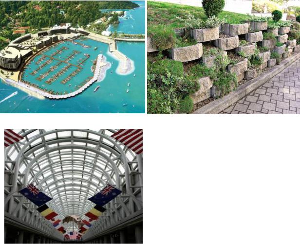
Engineering tasks where shell structures with a filler can be employed are as follows:
–– providing the passage of a vessel adjacent to the shore edge, safe arrival to the shore, loading/unloading in ports by erecting waterfront, enveloping and shore protection structures (Fig. 1а);
а) |
b) |
Fig. 1. Examples of shell structures:
а) waterfront project for Marina Pez Vela, Quepos, Costa Rica: D = 18 m, H = 15 m
(source: http://palplanches. arcelormittal.com/projects/display/title/Quepos);
b) example of a structure of a retaining wall (source: http://www.rcp.com.gh);
c) element of a structure of a carcass from bent (tubular) rods in the Chicago airport (USA)
(photo by the author)
c)
––providing the stability of transport water passage structures, bridge abutments, crossings, underground structures;
––vertical planning of areas for industrial, civil and transport construction: retaining walls from large and fine shell elements filled with subbase (Fig. 1b);
7

Scientific Herald of the Voronezh State University of Architecture and Civil Engineering. Construction and Architecture
––creating elements as part of carrying carcasses of buildings and structures (Fig. 1c) in structures of bridge farms and other rod structures filled with concrete (―guncrete‖), sand ―gun sand‖) and other materials;
––providing the strength and stability of the foundations of structures by putting shells in the subbase.
2. Application area. Two types of gravitational shell structures with a filler came to be used in two major ways: 1) integral steel cylindrical shell filled with large-fragmented subbase; 2) groove shells that make up an isolated contour that is filled with large-fragmented subbase inside.
The first of the above types of structures is widely used in Japan, Russia and the European Union.
Integral steel cylindrical shells (with a large diameter) consist of two major elements – a shell filled with a subbase and additional top layer. The shell can be made of steel, ferr o- concrete and some other types of polymers. The ratio of the major sizes of a structure is the following. The height to the diameter (H/D) of the shell ranges from 1,2 to 1,5. It is recommended that shells are applied on cliff, large-fragmented, sandy or clayous foundation subbases [19].
There are shells on either a preliminary designed rock foundation or on a subbase with the depth of the foot 1,5—2,5 m below the designed point by making preliminary cuts or floating by washing out or loading (the loading conditions depend on the characteristics of the foundation subbase). Deepening makes it possible for the foundation inside the shell to stick out and to be washed out. Sand, limestone or rocky subbase can be used to fill the shell. The bottom of the waterfronts are filled by strengthening each layer with a pervibrator. Weak subbases inside shells can be replaced by stronger ones or reinforced in some special ways [19].
The upper part of the shell is made of both a monolith ferroconcrete or assembled ferroconcrete elements [19] that can block the voids between the adjoining shells of the basin.
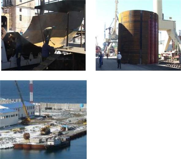
An example of this structure can be that of a waterfront in the Far East of Russia (Primorskiy Krai, Kozmino Bay) (Fig. 2). For Kozmino Bay 37 shells with the diameter of 8 m and height of 8 m, the thickness of a steel sheet is 0,016 m, the weight of each shell is 28 t.
Cylindrical groove shells (cofferdam) are commonly used by building companies of the USA and East Asia. Depending on the conditions of arrangement and designing requirements groove shells can be divided into three major groups:
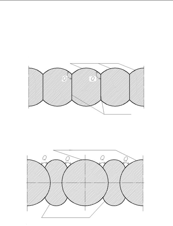
–– diaphragm shells (Fig. 3) are arranged by joining together individual straight-line segments or cylindrical arches. The resulting curved-line elements have the identical radius along the
8
Issue № 3(31), 2016 |
ISSN 2075-0811 |
entire structure being designed. The angle Q between the curved-line segment forming the shell and the longitudinal diaphragm is commonly 1200. The shells are taken out and filled along the entire length of the waterfront each 1,5 m of each layer along the height to avoid the deformation of the groove. The shell being put on is tightly connected with the already floated one as the deviation from the designed point of one shell might cause that of the entire row. Such a type of shells is used for small-sized structures with the ratio of the height to the width smaller or equalling one (Н/D ≤ 1);
–– cylindrical shells (Fig. 4) (cylindrical or semicircular shells joined together by the curved-line elements). They are made by joining individual curved-line elements at the angle Q = 30 ÷ 450. Filling of a shell does not depend on the way adjoining shells are filled. This structure is used for the height-diameter ratio Н/D = 1÷1,5;
а) |
b) |
Fig. 2. Construction of the waterfront using a largediameter shell in the Kozmino Bay:
а, b) making a steel shell;
c) putting the shells into the designed position (source: http://kaskad.vtvn.ru/news/964)
c)
9
Scientific Herald of the Voronezh State University of Architecture and Civil Engineering. Construction and Architecture
–– groove shells designed to be shaped like a clover leaf (Fig. 5) is four curved-line segments joined together and strengthened with a longitudinal diaphragm. The shells in a row are joined by arches. The difference between the adjoining sections of the shells when filled with a subbase is no more than 1,5 m. This type of shells is very challenging to make and is used for wider structures.
Diaphragm shell
Longitudinal diaphragm
Fig. 3. Scheme of an enclosure designed to consist of diaphragm shells
Cylindrical shells
Joining arches
Fig. 4. Scheme of an enclosure designed to consist of cylindrical groove shells
Cylindrical shells are most common structures using groove shells due to little difficulty involved in making them, which reduces the time for manufacturing, as well as longevity and cost efficiency.
10