

3291
.pdfIssue № 3(31), 2016 |
ISSN 2075-0811 |
Longitudinal diaphragm
Shells
Joining arches
Fig. 5. Scheme of an enclosure designed to be made of groove shells and shaped like a clover leaf
The shell is placed in several steps: the carcass frame is put in (Fig. 6) (―the core‖ of the future shell) to the design point: then a cylindrical shell is designed by putting in groove as deep as necessary (a way of floating a groove depends on the characteristics of the foundation subbase [20]), each groove is given a number according to the order it is placed into a shell; taking out weak subbase; filling the shell with a subbase with proper physical and mechanical characteristics (sand, limestone, large-fragment subbase) with each layer strengthened by a pervibrator each 1,5 m.
Groove
Element of a carcass frame
Fig. 6. Scheme of strengthening of a cylindrical groove shell
11
Scientific Herald of the Voronezh State University of Architecture and Civil Engineering. Construction and Architecture
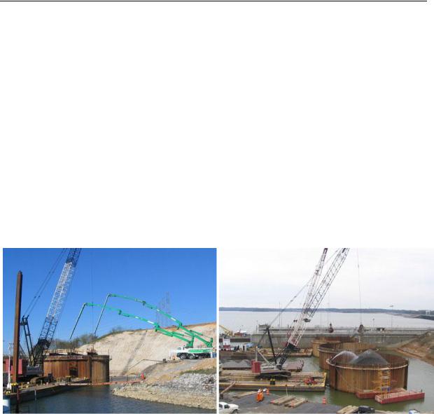
An example of this structure can be a project of a coast-protecting wall in the USA (Kentucky) (Fig. 7). The work on the project included placing cylindrical groove joints with the diameter 30 m and three joining arches.
The factors that contribute to the choice of integral shells early on at the designing stage or groove shells can be joined into three major groups:
––experience of a firm, necessary equipment;
––financial reasoning that has to do with the distance of an object and necessary infrastructure;
––optimal correlation of the construction and operating conditions. For engineers the third group of factors is of most interest as it reflects the features of the operation of a structure in construction and allowing an optimal solution depending on the conditions of a construction site and the parameters of the operation of a future object. These factors are central to the factors where one option is more preferable over the other.
а) |
b) |
Fig. 7. Placing a coast-protection wall in Paducah, Kentucky:
а, b) designing the structure of a shell and filling it with a subbase (sources: http://www.cjmahan.com/static/upstream.php,
http://www. lrn.usace.army.mil/Missions/CurrentProjects/Construction/KentuckyLockAdditionProject.aspx)
The choice of a particular type of a structure depends on the following factors:
–– characteristics of the foundation subbase. Cylindrical groove shells are recommended for use under complex engineering and geological conditions on a waterfront when the upper layers of the subbase are weak and loads need to be transmitted onto stronger bearing layers deep from the surface. Large-diameter shells are normally placed on a special strong foundation
(―bed‖) that cannot always be put in due to the complexity of underwater works [19];
12
Issue № 3(31), 2016 |
ISSN 2075-0811 |
–– availability of materials and equipment. It is often the crucial factor in choosing a type of a structure. A metal shell from an integral sheet or its components are a unique type of a structure that is manufactured in a plant in accordance with a project and is delivered to a construction site using heavyweight land or water transport. An assembly site contributes to the labour costs and construction times. Cylindrical groove shells are an optimal solution: the component of a structure –– a steel groove ––is chosen from a plant’s catalogue according to the calculation results and is delivered to the construction site over a shorter period as transportation is made less challenging;
––sizes of a structure being designed. Integral shells are mostly made as cylinders: they are put closely in a row or some distance away from one another that is gripped with a shell fragment of the same or a smaller radius (see Fig. 2). Other than that, the choice of the shapes of integral shells is rather limited. Conversely, cylindrical groove shells can be put together differently depending on a required configuraiton of a future enclosure (see Fig. 3—5, 7). The construction technology of these shells allows shells of considerably large diameters to be designed (of up to 30 m [20]);
––construction conditions. Enclosures using large-diameter shells are recommended for use in the ―water‖ construction when there are challenges involved in the construction of groove shells as groove piles cannot be floated [4];
––seismic loading. If there is some, integral shells should be supported by a dense base, which is not always possible. Groove shells can thus be an optimal solution.
3. Major construction models. The foundations of the shell theory date back to the 1940s [3, 12, 14, 18] and then were developed more specifically [5, 9—11, 13]. A range of complex analytical solutions for calculating isolated cylindrical shells (hollow and with a filler) mainly for locking a shell in the foundation by one of the ends [7, 18].
Studies into the shell theory with an interior hard massive (filler) are highly developed for calculating and designing solid-propellant engines [6, 8].
Calculation models for integral shells with a filler and groove shells are designed using one of the basics of the shell theory. In order to describe the strain-deformation of a filler, a model of a solid body is commonly employed where a filler is viewed as a homogeneous medium where there is a linear dependence between strains and deformations.
Depending on the sizes of a shell and the way it is loaded, different calculation models were developed based on three major types of strains and deformations of a structure:
––membrane – in the membrane shell theory there are stretching and compressing strains in thin (δ/R < 1/20, δ is the thickness of the wall, R is the radius of a shell) in rotation shells [2, 4];
13

Scientific Herald of the Voronezh State University of Architecture and Civil Engineering. Construction and Architecture
––semi-membrane – semi-membrane theory is applicable when there is compression accompanied with bend in thin-walled (δ/R<1/20) and middle-walled (δ/R ≈ 1/20) of cylindrical shells [3];
––membrane — the membrane theory is used to determine the strain and deformations in thin (δ/R < 1/20) shells for solid arrangements of the edges that in this case are conducive to a bend [15].
The operation of a large-diameter shell with an internal filler is most completely described by using the semi-membrane theory where there are approximated numerical values that are rather labour-intensive [1, 3, 9, 13, 14]. However, not in all cases it makes sense to employ the semi-membrane theory. Hence an increase in the thickness of the shell wall causes the filler subbase to stop to have an effect on the strength of concrete and to increase the stability by increasing the weight of a structure. As a result for a certain thickness a shell can be calculated using a more simple scheme of the gripped hollow ring beam.
Furthermore there is a solution of a preliminary choice of the theory of shell depending on the specified sizes of a structure (rations R/δ where δ is thickness of a shell, R is the radius of the shell) and an internal filler.
4. Applications of the calculation theory. The section presents the reasons why for preliminary calculations the semi-membrane calculation theory, which is rather challenging, should be used for isolated cylindrical shells with an internal filler depending on their size. Comparative calculations were thus performed using two theories – the general theory (for a hollow beam rigidly fixed on a foundation) and the semi-membrane one (the finite element method is employed for the shell rigidly fixed on a foundation taking into account the effect of the internal filling – subbase).
In order to analyze the results maximum strains were selected occurring in the most loaded areas of a structure: normal strains in the compressed area adjacent to the support which are crucial in choosing an appropriate thickness of a shell.
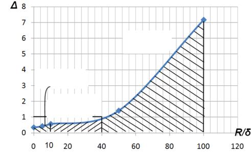
As a result for the investigated ratios of the sizes we have identified the ratio of normal strains in the compressed area of the structure computed using the semi-membrane theory to those according to the simplified console scheme: = σоб /σб (σоб are the strains of the shell (the semimembrane theory), σб are the strains of a gripped (simplified calculation scheme)).
As a result the range of the sizes of the shells is defined where the simplified calculation theory can be employed for preliminary calculations (Fig. 10).
14
Issue № 3(31), 2016 |
ISSN 2075-0811 |
Thin-walled
shells
Thick-walled
shells
Mediumwalled shells
Fig. 10. Ratio of the strains in the shell calculated using two different calculation schemes depending
on the size of the shell
As a result there are the following applications of the calculation theory:
–– for the ratio R/δ є (1;10) a shell structure can be computed using the simplified beam theory (calculated as a hollow beam with a ring section) considering the large remaining bearing capacity ( ≈ 0,4÷0,6);
––at R/δ є (10;40) strain-deformation of shell structures can be determined using the beam theory and for R/δ ≈ 40 the strains identified using it are close to those obtained as a result of calculations using the semi-membrane theory;
––at R/δ > 40 the calculation using the beam theory is not applicable; for this range even for preliminary calculations the semi-membrane theory must be employed.
Conclusions
As a result of this stage of the research the following results have been obtained:
1.Steel shells have been classified depending on their construction technology. Shells are grouped into two major types –– integral steel shells and groove shells (cofferdam).
2.Designing conditions where at the beginning integral large-diameter shells can be preferred over groove ones have been defined.
3.The criteria of preliminary calculations of shells depending on the ratio of their major sizes have been set forth. Based on the comparative calculations a range of the radius-thickness ratio has been computed where the calculation scheme for a gripped beam with a ring section or a model taking into account the semi-membrane strain-deformation of a structure is recommended.
15

Scientific Herald of the Voronezh State University of Architecture and Civil Engineering. Construction and Architecture
The analysis of the studies of shell structures indicates that it is essential to come up with comprehensive calculation methods that could made shell structures with an elastic filler more widely used for protective structures (in hydrotechnical construction) as well as in vertica planning of an area (in industrial, civil and transport construction). The calculation theory should rely on the analysis of the joint operation of a shell with an internal filler, account for the edge effects and retain the operation qualities of shell structures under static and dynamic loads.
References
1.Axelrad Е. L. Shell Theory and Its Specialized Branches. International Journal of Solids and Structures, 2000, no. 10, pp. 1425—1451.
2.Biderman V. L. Mekhanika tonkostennykh konstruktsiy [Mechanics of thin-walled structures]. Moscow, Mashinostroenie Publ., 1977. 488 p.
3.Vlasov V. Z. Izbrannye trudy: v 3 t. T. I [Selected works: in 3 vol. Vol. I]. Moscow, Izd-vo AN SSSR, 1962.
528p.
4.Gurevich V. B. Rechnye portovye gidrotekhnicheskie sooruzheniya [River port hydraulic structures]. Moscow, Transport Publ., 1969. 416 p.
5.Emel'yanov I. G., Kuznetsov V. Yu. Reshenie kontaktnykh zadach dlya tsilindricheskikh obolochechnykh konstruktsiy s uchetom tangentsial'nykh usiliy [Solution of contact problems for cylindrical shell structures tak-
ing into account the tangential effort]. Problemy mashinostroeniya i nadezhnosti mashin, 2000, no. 1,
pp. 59—64.
6.Ivanov P. L. Grunty i osnovaniya gidrotekhnicheskikh sooruzheniy [Soils and foundations of hydraulic structures]. Moscow, Vyssh. shk. Publ., 1985. 352 p.
7.Ivanov V. A., Safiullin F. Kh. Priblizhennyy raschet tsilindricheskikh obolochek s zapolnitelem. Nelineynaya teoriya obolochek i plastin: tezisy dokladov. [An approximate calculation of cylindrical shells with a filler: Nonlinear theory of shells and plates: proceedings]. Kazan, 1980, pp. 13—14.
8.Il'gamov M. A., Ivanov V. A., Gulin B. V. Prochnost', ustoychivost' i dinamika obolochek s uprugim zapolnitelem [Strength, stability and dynamics of shells with elastic filler]. Moscow, Nauka Publ., 1977. 332 p.
9.Cummings E. M. Cellular Cofferdams and Docks. ASCE Proc. Paper, 1957, no. 1366, no. WW3, p. 62.
10.Krys'ko V. A., Savel'eva N. E., Shagivaleev K. F. Statika i dinamika zamknutykh tsilindricheskikh obolochek pri neravnomernom poperechnom nagruzhenii [Statics and dynamics of closed cylindrical shells with nonuniform transverse loading]. Izvestiya vuzov. Mashinostroenie, 2005, no. 1, pp. 3—14.
11.Nerubaylo B. V., Ol'shanskiy V. P., Selemeneva Yu. I. Tsilindricheskaya obolochka, nagruzhennaya radial'nymi silami po krugovym oblastyam [Cylindrical shell loaded by radial forces on circular areas]. Inzhenernofizicheskiy zhurnal, 1997, no. 5, pp. 814—819.
12.Timoshenko S. P., Voynovskiy-Kriger S. Plastinki i obolochki [Of plates and shells]. Moscow, 1966. 632 p.
13.Ovesen N. L. Cellular Cofferdams, Calculation Methods and Model Tests. Danish Geotechnical Institute, 1962, no. 14, pp. 1—64.
16
Issue № 3(31), 2016 |
ISSN 2075-0811 |
14.Pikul' V. V. Sovremennoe sostoyanie teorii obolochek i perspektivy ee razvitiya [The current state of the theory of shells and its development prospects]. Mekhanika tverdogo tela, 2000, no. 2, pp. 153—168.
15.Tsurpal I. A. Soprotivlenie materialov. Laboratornye raboty [Mechanics of materials. Laboratory work]. Kiev, Vyssh. shk. Publ., 1988. 245 p.
16.Tsimbel'man N. Ya., Chernova T. I., Bekker A. T., Seliverstov V. I. Issledovaniya napryazhennodeformirovannogo sostoyaniya obolochechnykh konstruktsiy s napolnitelem [Studies of the stress-strain state of shell structures with a filler]. Vestnik Irkutsk. gos. tekhn. un-ta, 2013, no. 8, pp. 64—70.
17.Chernova T. I., Tsimbel'man N. Ya. Model'nye issledovaniya napryazhenno-deformirovannogo sostoyaniya obolochek bol'shogo diametra s napolnitelem [Simulation studies of the stress-strain state of large-diameter shells with the filler]. Vestnik Moskov. gos. stroit. un-ta, 2012, no. 12, pp. 71—78.
18.Shagivaleev K. F. Raschet prostranstvennoy sistemy iz dvukh obolochek, soedinennykh promezhutochnymi svyazyami [The calculation of a spatial system of two shells connected by intermediate links]. Vestnik Saratov. gos. tekhn. un-ta, 2006, no. 2, pp. 19—26.
19.R 31.3.02-98. Rekomendatsii po proektirovaniyu morskikh portovykh gidrotekhnicheskikh sooruzheniy v seysmicheskikh rayonakh pri nalichii v osnovanii slabykh gruntov (posobie k Instruktsii po proektirovaniyu morskikh prichal'nykh i beregoukrepitel'nykh sooruzheniy RD 31.31.55-93) [R 31.3.02-98. Recommendations for the design of sea port hydraulic structures in seismic regions in the presence of weak Foundation soils (guide to Instructions for designing marine berthing and shore facilities 31.31.55 RD-93)]. Vladivostok, Izd-vo AOOT «DNIIMF», 1998. 27 p.
20.Seredin P. V., Glotov A. V., Domashevskaya E. P. et al. Structural features and surface morphology of Alx- GayIn1-x-yAszP1-z/GaAs(100) heterostructures. Applied Surface Science, 2013, vol. 267, pp. 181––184.
17

Scientific Herald of the Voronezh State University of Architecture and Civil Engineering. Construction and Architecture
HEAT AND GAS SUPPLY, VENTILATION, AIR CONDITIONING,
GAS SUPPLY AND ILLUMINATION
UDC 542.47:66.047
A. V. Barakov1, A. P. Byrdin2, A. A. Nadeev3
STUDY OF HEAT AND MASS TRANSFER IN THE DRYER
WITH A PSEUDO LIQUEFIED LAYER OF A DISPERSE MATERIAL
Voronezh State Technical University
Russia, Voronezh, tel.: (473)243-76-62, e-mail: pt_vstu@mail.ru
1D. Sc. in Engineering, Prof., Head of the Dept. of Theoretical and Industrial Heat Power Engineering
2PhD in Physico-Mathematical Sciences, Assoc. Prof of the Dept. of Applied Mathematics and Mechanics
3PhD in Engineering, Senior Lecturer of Dept. of Theoretical and Industrial Heat Power Engineering
Statement of the problem. It is known that obtaining exact solutions of equations in a rather general theoretical model of heat and mass transfer in drying of dispersed materials is very problematic. However, many models describing such processes allow the use approximate analytical methods, for example, asymptotic methods.
Results. We have obtained time dependences of the heat capacities and temperatures of the solid and gaseous phase of a liquefied layer. The dependences of the relaxation times of heat capacity and temperature on the kinetic and thermophysical parameters of the phases were obtained. The expressions for the temperature of the material and gas for time, which is considerably exceeds the relaxation time are presented.
Conclusions. For the first time the solution of singularly and regularly perturbed system of equations describing the balance of mass and heat in a liquefied layer has been obtained using the asymptotic method.
Keywords: liquefied layer, heat and mass transfer, asymptotic methods.
Introduction
Drying is one of the most common thermal technological processes in building industry. Its arrangement involves a great deal of thermal energy, which is why it is necessary to choose the most viable ways of developing effective dryers. They cannot be designed without mathematical modelling of exchange processes involved.
© Barakov А. V., Byrdin А. P., Nadeev А. А., 2016
18

Issue № 3(31), 2016 |
ISSN 2075-0811 |
Obtaining accurate solutions for equations in a rather general theoretical model of heat and mass transfer during drying of disperse materials is known to pose problems. This might be due to non-linearity of equations or no possibility of writing boundary conditions analytically. In these cases either a numerical solution of model equations is used to simplified models are designed that can be used in certain conditions or structural features of devices. Some models describing exchange during drying in a pseudoliquefied layer along with numerical solutions assume approximated analytical methods as well as asymptotical ones.
This paper is a follow up of a series of analytical studies of classical models of heat and mass exchange between disperse material and a heat carrier liquefying a layer based on asymptotic methods [1—3]. The above papers dealt with exchange processes between a dispersion and continuous phases or a boiling layer or a pseudoliquefied layer with a directed motion of material [3] using the regular or singular perturbation theory [4]. In solutions of differential equations of the model there supposed to be one regular or singular parameter that was considered small compared to other dimensionless parameters included in model equations of exchange. Regular parameters of perturbation in a dimensionless form were phenomenological parameters by A.V. Lykov [5] – the drying rate (in the first period) or a drying coefficient (in the second period of mass exchange).
Singular perturbation in the model equations was a gas content parameter, i.e. a ratio of the masses of a heat carrier and material in a pseudoliquefied layer.
The present paper deals with the solution of a system of differential equations describing the temperature of the solid and gaseous phase of the layer when there is a directed motion of the solid phase and the model equations contain both regular and singular perturbation.
1. Equations of the mathematical model. The original model equations for exchange in a dynamic layer are accepted to be ratios of mass and energy balance for the disperse and continuous subsystems of the layer [6] reformulated in terms of the heat capacities of the phases [3]. Therefore let us obtain the following original task for a system of vector equations:
|
|
|
|
|
|
|
|
|
ˆ |
|
|
|
|
|
|
|
|
|
|
|
|
ˆ * |
|
|
* |
( ) b , |
|
(1) |
|
|
|
|
|
|
|
|
E C |
( ) BC |
|
|||||
|
|
|
|
|
|
ˆ ˆ* |
|
|
ˆ |
|
|
|
|
|
|
|
|
|
|
|
|
|
|
|
|
(2) |
|||
|
|
|
|
|
|
E C |
( ) ( ) A( ) ( ) a( ) , |
|||||||
|
|
|
|
|
|
|
|
|
colon 1,1 , |
|
|
|||
|
|
|
|
|
|
C* (0) (0) |
|
|
||||||
where j t t |
0 |
, |
j G |
M |
1 |
, t is the time of observation, sec; t0 |
is the time of the start of |
|||||||
|
|
2 |
|
|
|
|
|
|
|
|
|
|
||
the second period of drying, sec; M2  M1 is the gas content of the layer;
19

Scientific Herald of the Voronezh State University of Architecture and Civil Engineering. Construction and Architecture
*
ˆ |
diag |
1, , |
ˆ |
* |
( ) |
|
|
|
|
|
|
|
* |
|
|
|
|
|
|
|
* |
( ) , |
* |
( ) colon |
* |
|
|
|
|
|
* |
( ) , |
|
||||||||||||||||||||||||||
E |
С |
diag С1 ( ),С2 |
С |
|
С1 |
( ),С2 |
|
||||||||||||||||||||||||||||||||||||||||||||||||||||
( ) colon ( ), ( ) , |
С* ( ) |
Ck ( ) |
|
, c |
|
|
|
С (0) , |
|
( ) |
Tk ( ) |
, ( k 1, 2 ), |
|
||||||||||||||||||||||||||||||||||||||||||||||
|
|
|
|
|
|
|
|
|
|
|
|
|
k |
|
|
|
|
|
ck 0 |
|
|
|
|
|
k 0 |
|
|
|
k |
|
|
|
|
|
|
|
|
k |
|
|
|
Tk |
(0) |
|
|
|
|
|
|
|
|
|
|||||||
|
|
|
|
|
|
|
|
|
|
|
|
|
|
|
|
|
|
|
|
|
|
|
|
|
|
|
|
|
|
|
|
|
|
|
|
|
|
|
|
|
|
|
|
|
|
|
|
|
|
|
|
|
|||||||
|
|
C1 ( ) с1 сж w1 ( ) , C2 ( ) с2 |
|
|
|
|
|
|
|
|
|
|
|
|
ˆ |
|
bij |
, ( i, j 1, 2 ), |
|
|
|
|
|
||||||||||||||||||||||||||||||||||||
|
|
|
сп w2 ( ) , B |
|
|
|
|
|
|||||||||||||||||||||||||||||||||||||||||||||||||||
|
|
|
|
, |
|
|
|
0 , |
|
|
|
|
|
|
|
|
пж |
|
|
|
|
|
|
1 |
|
|
|
|
|
|
|
|
, |
|
|
|
|
|
|
||||||||||||||||||||
|
|
b |
b |
|
|
|
b |
|
|
, |
b |
|
|
|
, b colon b ,b |
|
|
|
|
|
|
||||||||||||||||||||||||||||||||||||||
|
|
11 |
|
|
12 |
|
|
|
|
|
|
21 |
|
|
|
|
|
0 |
|
с |
|
|
|
|
|
22 |
|
|
|
|
|
|
|
|
|
|
|
|
|
|
|
1 |
2 |
|
|
|
|
|
|
|
|
|
|
||||||
|
|
|
|
|
|
|
|
|
|
|
|
|
|
|
|
|
|
|
|
|
|
|
|
|
|
|
|
|
|
|
|
|
|
|
|
|
|
|
|
|
|
|
|
|
|
|
|
|
|
|
|
|
|
|
|
|
|
|
|
|
b fK C* |
, b 1 b |
|
|
, |
|
|
|
fK |
|
, |
|
|
|
G1 |
, |
f |
S |
, |
S |
|
|
|
G2c20 |
, |
(3) |
|||||||||||||||||||||||||||||||||
|
|
|
0 |
|
0 |
0 |
|
0 |
|
|
|||||||||||||||||||||||||||||||||||||||||||||||||
|
1 0 |
0 |
р |
|
|
2 |
|
|
|
|
21 |
|
|
|
|
|
|
|
|
|
|
|
|
|
|
|
|
|
|
G2 |
|
|
|
|
S0 |
|
|
|
|
|
21 |
|
|||||||||||||||||
|
|
|
|
|
|
|
|
|
|
|
|
|
|
|
|
|
|
|
|
|
|
|
|
|
|
|
|
|
|
|
|
|
|
|
|
|
|
|
|
|
|
|
|
|
|
|
|
|
|
|
|
||||||||
|
|
kc |
|
c |
|
|
|
|
|
|
|
|
c |
|
|
|
|
|
* |
|
|
|
|
с1 сж w1 р |
|
|
ˆ |
|
|
|
|
|
|
|
|
|
|
|
|
|
|
|
|
||||||||||||||||
|
|
|
|
|
|
|
|
|
|
|
|
|
|
|
|
|
|
|
|
|
|
|
|
|
|
|
|
|
|
|
|
|
|
|
|
|
|
||||||||||||||||||||||
|
|
20 |
|
|
20 |
|
|
|
|
|
|
|
п |
|
|
, Cр |
|
|
|
|
|
|
|
|
|
|
|
|
|
|
|
|
|
|
|
|
|
|
|
|
|
|
|
|
|
|
|
||||||||||||
K0 |
|
|
|
, с |
|
|
|
, пж |
|
|
|
|
|
|
|
|
|
|
|
|
|
|
|
|
|
|
, A( ) |
|
aij |
|
, ( i, j 1, 2 ), |
|
|||||||||||||||||||||||||||
21 |
c10 |
cж |
|
|
|
|
|
|
с10 |
|
|
|
|
|
|
||||||||||||||||||||||||||||||||||||||||||||
|
|
|
|
|
|
|
|
|
|
|
|
|
|
|
|
|
|
|
|
|
|
|
|
|
|
|
|
|
|
|
|
|
* |
|
|
|
|
|
|
|
|
|
|
|
|
|
|||||||||||||
|
|
|
|
|
|
|
|
|
|
|
|
|
|
|
|
|
|
|
|
|
|
|
|
|
, |
a11 ( ) 0 |
|
|
|
|
|
|
|
|
|
|
|
|
|
|
|
|
|
|
|
||||||||||||||
|
|
|
|
a( ) colon a1( ), a2 ( ) |
сC1 ( ) , |
|
|
|
|
|
|
|
|
|
|
|
|||||||||||||||||||||||||||||||||||||||||||
|
|
|
|
|
|
|
|
|
|
|
с |
f |
0 |
1 C* ( ) |
|
, a12 ( ) 21 с f , |
|
|
|
|
|
|
|
|
|
|
|
|
|
||||||||||||||||||||||||||||||
|
|
|
|
a21 ( ) |
|
|
|
|
|
|
|
|
|
|
1 |
|
|
|
|
|
|
|
|
|
|
|
|
|
|
|
|
|
|
|
|
||||||||||||||||||||||||
|
|
|
|
|
|
|
|
|
21 c |
|
|
|
|
|
|
|
|
|
|
|
|
|
|
|
|
|
|
|
|
|
|
|
|||||||||||||||||||||||||||
|
|
|
|
|
|
|
|
|
|
|
|
|
|
|
|
|
|
|
|
|
|
|
|
|
|
|
|
|
|
|
|
|
|
|
|
|
|
|
|
|
|
|
|
|
|
|
|
|
|
|
|
|
|||||||
|
|
|
|
a22 |
( ) f C2 |
( ) |
|
|
|
|
|
|
|
|
|
|
|
|
|
|
|
|
|
r1 |
|
|
|
|
|
|
|
|
|
|
, |
|
|
|
|
|
|
|
|
|
|
|
|||||||||||||
|
|
|
|
, a1 ( ) 0 1 |
|
1 C1 ( ) |
|
|
|
|
|
|
|
|
|
|
|
||||||||||||||||||||||||||||||||||||||||||
|
|
|
|
|
|
|
|
|
|
|
|
|
* |
|
|
|
|
|
|
|
|
|
|
|
|
|
|
|
|
|
|
|
|
|
|
|
|
* |
|
|
|
|
|
|
|
|
|
|
|
|
|
|
|
||||||
a ( ) 1 r 1 пж |
|
|
1 C* ( ) |
, |
|
|
|
|
|
|
T2 (0) |
, |
|
r |
|
|
r |
|
, r |
|
|
|
r |
. |
|
||||||||||||||||||||||||||||||||||
2 |
|
|
|
2 |
с |
|
0 |
|
|
|
1 |
|
|
|
|
|
|
|
|
21 |
|
|
T1 (0) |
|
|
1 |
|
|
|
cжT1 (0) |
2 |
|
|
|
cпT2 (0) |
|
|||||||||||||||||||||||
|
|
|
|
|
|
|
|
|
|
|
|
|
|
|
|
|
|
|
|
|
|
|
|
|
|
|
|
|
|
|
|
|
|
|
|
|
|||||||||||||||||||||||
Here c1, c2, cж, cn are specific heat capacities of a dry material, dry gas, liquid and vapour, J/(kg K); w1(τ), w2(τ) are current moisture contents of the material and gas, kg/kg; M1, M2 are the mass of the material and gas in the layer, kg; G1, G2 are the mass consumptions of the material and gas, kg/sec; w1p are equilibrium moisture contents of the material, kg/kg; T1(τ), T2(τ) are absolute temperatures of the material and heat carrier in the layer, K; S is the total area of the surface of the particles of the material, m2; r is the specific heat of vapour generation, J/kg; k is the drying coefficient, kg/(m2 sec); α21 is the coefficient of the heat exchange between the material and heat carrier, Watt/(m2 K).
2. Asymptotic solution of the model equations. The system of vector differential equations
(1) and (2) for a small gas content of the pseudoliquefied layer and a small drying coefficient is singularly perturbed for a γ system of equations. Using the asymptotic method [4], the solution of the equation is as follows
|
N |
|
|
(s) , |
|
( ) |
|
||||
C |
m n C(m,n) ( ) (m,n) |
(4) |
|||
|
k 0 m n k |
|
|
|
|
|
N |
|
|
|
|
( ) |
m n (m,n) |
( ) (m,n) (s) , |
(5) |
||
k 0 m n k
20