

3291
.pdfIssue № 3(31), 2016 |
ISSN 2075-0811 |
UDC 624.04
M. N. Kirsanov1
STRESS STATE AND DEFORMATION
OF A RECTANGULAR SPATIAL ROD COVER
National Research University «MPEI»
Russia, Moscow, tel.: (495)362-73-14, e-mail: c216@Ya.ru
1D. Sc. in Physics and Mathematics, Prof.
Statement of the problem. The scheme is considered statically determinate elastic regular farm type with an arbitrary number of cells on the sides simulating the rectangular surface. The farm is symmetric, the cell size in each direction is constant. The farm has seven external relations — the spherical hinge, and two vertical cylindrical rods located in the corners of the structure. The farm operates uniformly distributed over the nodes of the lower belt load. An analytical solutions for efforts in the rods and deflection of the farm is sought.
Results. Using the formula of Maxwell-Mohr the analytical dependence of a deflection of center farm from farm size and number of hinges side by side was obtained. The desired pattern was determinate by means of a computer algebra system Maple using recursion with two parameters.
Conclusions. A minimum was found in the dependence of the deflection on the number of panels to optimize the size of the structure. The asymptotics of the deflection according to the number of panels was identified.
Keywords: spatial farm, surfacing, deflection, limit properties, analytical solution.
Introduction
The number of statically determinate farms is limited. Searching for new structures is a task in its own right [1, 2]. The present paper looks at a rectangular in a plan and spatial farm with a flat face [3, 4].
A spatial statically determinate farm is commonly a solid body with six degrees of variety and six rod connections respectively which can model either a spherical or a cylindrical hinge. For such systems which are planned to be rectangular, there statistically can be no four vertical support rod at the edges as three points determine a plane.
The suggested scheme of a rectangular rod plate is uncommon as there are vertical supports along all the four angles of a farm and the farm itself (without supports) is a mechanism with
© Kirsanov М. N., 2016
71
Scientific Herald of the Voronezh State University of Architecture and Civil Engineering. Construction and Architecture
one degree of variety. There are seven rods in total. A farm is a regular structure with two independent parameters that equal the number of cells along the sides of a farm. The regular shape of a farm allows the solution for its stress strain to be obtained using the induction method by means of a method developed in [3—5] with the help of a modern system of a symbolic mathematics Maple [5].
The results obtained by means of the induction method do not restrict the number of elements based on how accurate they are and timing of calculations thus resulting in compact formulas for strengthening rods and bends.
The analytical solution can be either a part of the solution of a statistically undeterminate system using the force method (for calculating the major system) or be an independent value, e.g. a trial solution.
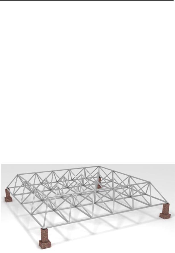
1. Scheme of a farm. A farm is a spatial statically determinate structure with two parallel rod contours and four-faced pyramid-like domes over the lower contour (Fig. 1—3). The rods are joined with hinges. The lower contour is a rectangular grid with panels (cells) sized a×b. Along the axis x the belt contains n cells with a side a, along the axis y — m cells sized b. In total there are N = nm cells in this contour. Over each cell there is a pyramid with the height h from four identical rods. The tops of the pyramids along the sides of the structure join the rods of the upper contour. The tops of the interior pyramids are not joined together.
Fig. 1. Farm. General view
72
Issue № 3(31), 2016 |
ISSN 2075-0811 |
In the lower contour there are K (n 1)(m 1) |
hinge joints and 2N n m rods, in the up- |
per one there are nm joints and 2(m n 2) rods. Considering 4N rods of the pyramids there are ns 6N 3(n m) 4 rods and nu N K hinges. Along with seven support rods the number of unknown efforts in the rods of the structure is identical to the number of the equilibrium equations of the projections of the joints onto three coordinate axes:
ns 7 6N 3(n m) 3 3(N K ) . |
(1) |
The system is statically determinate. Note that there are four vertical supports in the structure supporting the plane of the lower contour. One of the supports seems excessive as the plans determined three points. But there is no contradiction as one of the support rods is from the farm itself. The structure is not a solid (unchangeable) body without the above seven support rods making up the four angle supports (Fig.1 does not specify the way they were fixed). It is only in conjunction with the support rods that the task seems correct, which is proved by the identity (1). The analytical calculation of a bend of a central node of similar farms caused by a concentrated force is in [3, 4].
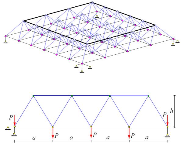
Fig. 2. n 4, m 6
Fig. 3. Side view, n 4
73
Scientific Herald of the Voronezh State University of Architecture and Civil Engineering. Construction and Architecture
Upper contour
Lower contour
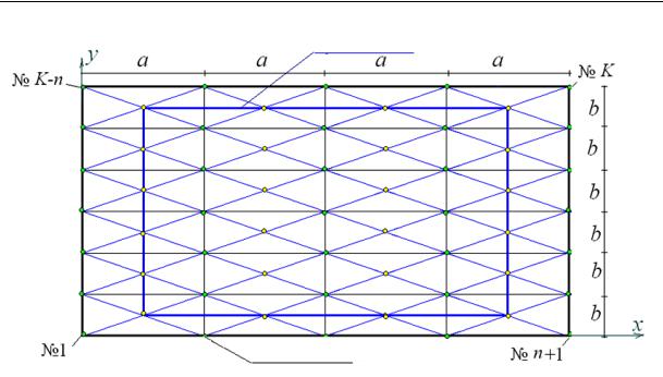
Fig. 4. Farm in a plan, n 4, m 6
The efforts will be calculated by cutting the nodes to make up a projection of the equilibirum equation. The direction cosines of the efforts will be determined using the coordinates of the ends of the rods. For that we introduce a system of coordinates with the axes x and y along the sides of a horizontal pavement and a vertical axis z. The start of the coordinates will be in the spherical support. In their lower contour there are nodes with the coordinates
rk [xk , yk , zk ] [(i 1)a, ( j 1)b, 0],
k i ( j 1)(n 1), i 1,..., n 1, j 1,..., m 1.
The coordinates of the nodes of the upper belt (the tops of the pyramids):
rk [(i 1/ 2)a, ( j 1/ 2)b, h],
k i ( j 1)n K, i 1,..., n, j 1,..., m.
The spherical support is modelled with three rods joined to the node 1. The coordinates of the ends of these rods joined on site are as follows
rk 1 [x1, y1, z1 1], |
rk 2 [x1, y1 1, z1 ], |
rk 3 [x1 1, y1, z1 ], k N K.
The cylindrical hinge is modelled with two rigid rods fixed in the node numbered n 1. The coordinates of their ends on the foundation are as follows:
rk 4 [xn 1, yn 1, zn 1 1],
74
Issue № 3(31), 2016 |
ISSN 2075-0811 |
rk 5 [xn 1, yn 1 1, zn 1 ], k N K.
Two individual stands at the other angles of the structure (the nodes K n and K (Fig. 4)) have the following coordinates of the ends fixed on the foundation:
rk 6 [xK n , yK n , zK n 1],
rk 7 [xK , yK , zK 1], k N K.
The structure is also specified by the order of joining the rods and nodes. For that each of ns rods is a conditional vector qi , i 1,..., ns where the coordinates are the number of the nodes it is joined to. From the viewpoint of the graph theory [6] this way corresponds to specifying a list of the ribs of the graph. In this case in order to calculate the direction cosines of the efforts from the equilibrium equation, it would be better to describe them in such a manner. Obviously the selected directions of the rod vectors do not affect the efforts and signs of the efforts in the rods. The vectors of the rods of the domes supported by the lower contour are as follows
qk [k j 1, k K ], |
qk N [k j, k K ], |
qk 2 N [k j 1 n, k K ], |
qk 3N [k j n, k K ], |
k i ( j 1)n, i 1,..., n, j 1,..., m.
The longitudinal rods of the lower contour grid are specified by the vectors:
qk 4 N |
[k j 1, k j], k i ( j 1)n, |
i 1,..., n, j 1,..., m 1, |
longitudinal rods: |
|
|
qk 5 N |
[k n, k 1], k i j(n 1) 1, |
i 1,..., n 1, j 1,..., m . |
The upper contour joining the tops of the end pyramids and making the side perimeter of the structure corresponds with the following vectors of the rods:
qk 6 N [K i, K i 1], k i n m,
qk 6 N [i 2mn m 1,i 2mn m 2], k i 2n m 1, i 1,..., n 1
and
qk 6 N [N in m 2, K in 1], k i 3n m 2,
qk 6 N [in K,in K n], k i 3n 2m 3, i 1,..., m 1 .
Seven support nodes are coded with the following vectors:
qns i [1, K N i], i 1, 2, 3, qns i 3 [n 1, K N i 3], i 1, 2, qns 6 [K n, K N 6], qns 7 [K , K N 7].
75

Scientific Herald of the Voronezh State University of Architecture and Civil Engineering. Construction and Architecture
2. Calculation of the efforts. The algorithm of designing a system of equations by cutting out the nodes is based on calculating the direction cosines of the efforts computed using the specified coordinates and their organization into the matrix G. The equilibrium equation is reduced to the system
|
|
|
|
|
|
|
, |
(2) |
|||
|
|
|
GS |
R |
|||||||
|
|
|
|
|
|
|
|
||||
where S |
is the vector of the efforts in the rods; T |
is the vector of the loads. |
|
||||||||
Let us consider when there is an even number |
of nodes on each side of |
the structure: |
|||||||||
m 2m0 , |
n 2n0 . There is a geometrically central node of the grid of the lower contour in |
||||||||||
the farm to which a vertical (along the axis z ) single load is applied and using the Max-
Moore formula a bend in the farm in this node can be found (Fig. 1). The load is ascribed to a corresponding vector component R in the right part of the system (2). The central node is numbered n1 2m0n0 m0 n0 1 . The vector components of the loads R numbered 3i 2 corresponds with the directions of the force along the axis x , numbered 3i 1 — along the axis y and numbered 3i — along the axis z (vertically). Here i 1,..., nu . Thus we have two variants of the load vector: RP,3 j P , j 1, 2,..., K , is the load of the distributed forces P,
and R1,3n1 1 from a single force. The remaining vector components R are zero. For the equilibrium equations we need projections of the rod vectors onto the coordinate axes which are computed using a difference of the coordinates of the hinges at the ends of the rod:
|
|
|
lx,i xq |
xq |
, ly,i yq |
yq |
,lz,i |
zq |
zq . |
|||||||
|
|
|
|
|
|
|
i ,1 |
i ,2 |
|
i ,1 |
i ,2 |
|
|
|
i ,1 |
i ,2 |
The quadratic matrix nS nS |
of the direction cosines G has the components: |
|||||||||||||||
|
|
|
G3q |
2,i lx,i / li |
, G3q |
1,i ly,i / li |
, G3q |
,i lz,i / li , |
||||||||
|
|
|
|
|
i ,1 |
|
|
|
i ,1 |
|
|
|
i ,1 |
|
|
|
|
|
|
G3q |
2,i |
lx,i / li , G3q |
1,i ly,i / li , G3q |
|
,i lz,i / li , |
||||||||
|
|
|
i ,2 |
|
|
|
|
i ,2 |
|
|
|
i ,2 |
|
|
||
|
|
|
|
|
|
1,..., n . |
|
|
|
|||||||
where l |
l2 |
l2 |
l2 |
, i |
The first index |
q |
is the number of the rod i, for the |
|||||||||
i |
x,i |
y,i |
z,i |
|
|
|
S |
|
|
|
i, j |
|
|
|
|
|
second one |
j 1, 2,3 is the number of the projection (on the axis x, y, z). In order to solve the |
|||||||||||||||
system of the linear equations (2) symbolically we use the calculation of the reverse matrix
which is simply G 1 |
1/ G in Maple. Using it the system is solved by multiplying the matrix |
||||||||||||||||
|
|
|
G 1 |
|
|
|
|
|
G 1 |
|
|
|
|
|
|
|
|
by the load vector S |
P |
R |
|
, |
|
S |
R |
where S |
P |
, S |
are the vectors of the efforts caused |
||||||
|
|
|
P |
|
1 |
1 |
|
1 |
|
||||||||
by the load and a single vertical force applied to the centre of the structure. This simple method does not require that a special software LinearAlgebra is employed and takes less time to
76

Issue № 3(31), 2016 |
ISSN 2075-0811 |
be transformed. Besides in order to calculate the results for another load the matrix does not need to be processed again and it takes less time to be transformed as well.
The result obtained by using the software is the analytical expressions for the efforts in the rods of the farm. In order to calculate a bend of the node where the load is applied, let us employ the Max-Moore formula:
N |
S |
S l |
|
|
ns |
S |
S l |
|
|
|
|
P |
|
P, j 1, j |
j |
|
|
|
P, j 1, j |
j |
|
, |
(3) |
|
EF |
|
|
EF |
|
||||||
j 1 |
|
|
|
j N 1 |
|
|
|
|
|
where E is the elasticity modulus of the rods; γF, F are the areas of the section of the rods of the domes and those of the belt respectively; γ is a dimensionless parameter describing a ratio of the sections of the rods of the domes and horizontal belts; lj is the length of the j-th rod; SP,j are the efforts in the j-th rod caused by the load; S1,j is the effort caused by a single vertical force applied to the centre of the structure. The parts are summed in all of the rods except
those in the support which are supposed to be rigid: j = 1, …, ns.
Let us introduce EF / Psum where Psum is the total load on all the K (n 1)(m 1) belts
of the lower belt of the farm (including the supports) and the load on each node |
P Psum / K . |
|||||||||||||
A relative bend of the upper node of the farm is calculated using the induction method: |
||||||||||||||
|
|
|
|
|
|
A |
a3 |
B |
b3 C |
n,m |
c3 |
/ |
|
|
|
|
|
|
|
n,m |
|
n,m |
|
|
|
|
|
||
|
|
|
|
|
|
|
|
|
|
|
|
|
, |
(4) |
|
|
|
|
|
|
|
16h2 |
|
|
|
||||
|
|
|
|
|
|
|
|
|
|
|
|
|
||
|
|
|
|
|
|
|
||||||||
where c a2 b2 |
4h2 |
is the length of the rod of the dome; |
|
|
|
|||||||||
|
|
A |
n(5n3 (m 3) 24n2 |
4(7m 3)n 24(m 1)) / 48 ; |
|
|||||||||
|
|
n,m |
|
|
|
|
|
|
|
|
|
|
|
|
|
B |
A |
|
; C |
((m2 |
2m 2)n2 2m(m 4)n 2(m2 4)) / 8. |
|
|||||||
|
n,m |
m,n |
n,m |
|
|
|
|
|
|
|
|
|
|
|
The coefficient An,m, Bn,m and Cn,m were obtained in two steps. First for the fixed m the coefficients An,1, An,2, … and Cn,1, Cn,2, … were obtained using the induction method with n sequential calculation in a symbolic form in Maple. Then the common members of the obtained sequences were found. Special Maple operators rgf_findrecur and rsolve were employed. In order to find the coefficient Bn,m an obvious symmetry condition of the formulas using the variables a, b and m, n was used.
3. Analysis. The obtained result (4) for the bend of the farm is on the one hand applicable for practical calculations of actual structures due to its general form. On the other hand co n- sidering that in practice there are more statically indeterminate structures obtained, e.g., by adding rods of the upper belt joining all the tops of the pyramid to the above farm. This s o- lution can be just evaluation of a bend and a part of the solution (a calculation of the major
77
Scientific Herald of the Voronezh State University of Architecture and Civil Engineering. Construction and Architecture
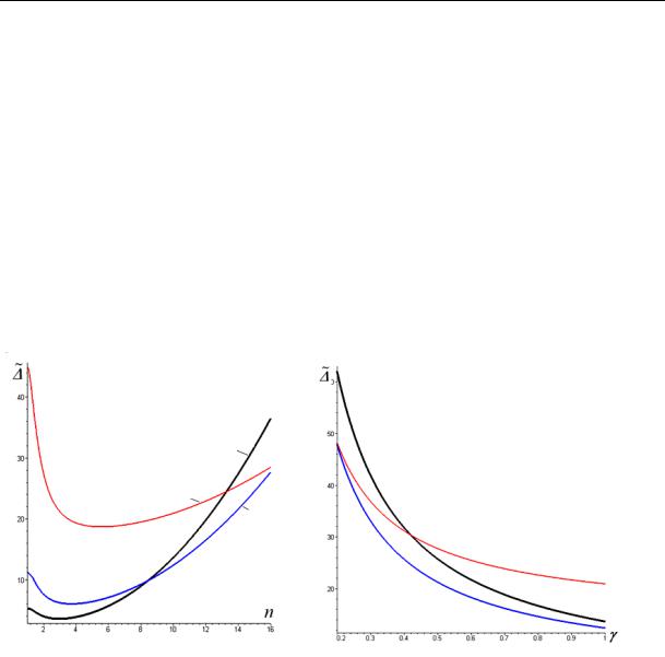
system) involving a statically indeterminate farm by means of the force method. Furthermore an isolated analytical form of the result allows for some characteristic features of the structure to be identified. If graphs of a dependence of a bend of a square farm with an ide n- tical number of the panels along the sides and a fixed length of the side (m = n, a = b = L/n) on the number of panels (Fig. 5), we can note that there is a minimum on curved lines. Intersection of the curved lines designed for different heights of the domes shows that for some n the farm has an identical rigidity. At n < 9 the position of the curved lines makes sense: the higher the domes are, the smaller is a bend, then as the number of panels increases (at the same sum load and the same size in the plan) it all changes: the curved line corresponding with h = 3 m is between the curved lines h = 1 m and h = 2 m and at n > 13 the farm with such a height becomes most flexible.
h = 3 m h = 1 m
h = 2 m
h = 1 m
h = 3 m
h = 2 m
Fig. 5. L = 10 m, γ = 1 |
Fig. 6. L = 10 m, n = 10 |
The dependence of a bend on the parameter of redistribution of the areas of the section γ at the fixed n = 10 (Fig. 6) also has identical effects. Intersection of the curved lines at γ = 0,2 and γ = 0,43 indicates the solution as being ambiguous, which is typical of a non-linear solution (4). Besides, the analytical dependence (4) allows the structure to be asymptotically studied by obtaining the information which can be obtained exclusively by means of numerical methods. One of the useful characteristics of the structure is a limited ratio of a bend to the degree of the number of panels [7]. The ratio is computed for a fixed span and sum load. The operator limit in Maple yields the following result:
lim / n2 h / (16 ) ,
n
which agrees with the general character of the curved lines in Fig. 5 with the same minimum.
78
Issue № 3(31), 2016 |
ISSN 2075-0811 |
Conclusions
An analytical solution for a bend in a spatial statically determinate farm of an evenly distributed along the nodes lower belt of the structure. The parameters of the solution are the sizes of the farm, load and the number of panels along its sides. An isolated compact form of the analytical solution allows its features to be analyzed and particularly for the character of a bend when the number of the panels of the farm increases when its size does not to be studied. This dependence was found to be quadratic.
Inductive solutions for the efforts in rods and bends indicate that as the number of panels increases, so does the time of transformations while the rate of numerical calculations does not change significantly. This is the reason why analytical solutions should be checked numerically by specifying all the original data in a certain form. However numerical methods might involve approximation errors which are hardly discernible for small farms and those existing at n > 100—200 as according to (1) the size of a matrix of a system of equilibrium equations increases in a quadratic dependence on n. One of the purposes of accurate results is to address what is referred to as ―the curse of dimensionality‖.
References
1.Hutchinson R. G., Fleck N. A. Microarchitectured Cellular Solids — the Hunt for Statically Determinate Periodic Trusses. ZAMM Z. Angew. Math. Mech, 2005, vol. 85, no. 9, pp. 607—617.
2.Hutchinson R. G., Fleck N. A. The Structural Performance of the Periodic Truss. Journal of the Mechanics and Physics of Solids, 2006, vol. 54, no 4, pp. 756—782.
3.Kirsanov M. N. Analiticheskiy raschet prostranstvennoy sterzhnevoy regulyarnoy struktury s ploskoy gran'yu [Analytical calculation of the space-frame structure with regular flat face]. Stroitel'naya mekhanika i raschet sooruzheniy, 2015, no. 2 (259), pp. 2—6.
4.Kirsanov M. N. Analiz progiba fermy pryamougol'nogo prostranstvennogo pokrytiya [Analysis of deflection of rectangular farm spatial coverage]. Inzhenerno-stroitel'nyy zhurnal, 2015, no. 1 (53), pp. 32—38.
5.Kirsanov M. N. Maple i Maplet. Reshenie zadach mekhaniki [Maple and Maplet. The solution of mechanics problems]. St. Petersburg, Lan' Publ., 2012. 512 p.
6.Kirsanov M. N. Grafy v Maple [Graphs in Maple]. Moscow, Fizmatlit Publ., 2007. 168 p.
7.Tin'kov D. V. Sravnitel'nyy analiz analiticheskikh resheniy zadachi o progibe fermennykh konstruktsiy [Comparative analysis of analytical solutions to the problem of deflection of truss structures]. Inzhenernostroitel'nyy zhurnal, 2015, no. 5 (57), pp. 66—73.
79

Scientific Herald of the Voronezh State University of Architecture and Civil Engineering. Construction and Architecture
CITY PLANNING, PLANNING OF VILLAGE SETTLEMENTS
UDC 711.581-168
V. N. Melkumov1, S. V. Chuykin2, A. A. Melnikova3
TERRITORIAL PLANNING OF RECREATIONAL AREAS
ADJACENT TO A RESIDENTIAL DEVELOPMENT AREA
Voronezh State University of Architecture and Civil Engineering
Russia, Voronezh, tel.: (473)271-53-21, e-mail: ser.chu@mail.ru
1D. Sc. in Engineering, Prof., Head of Dept. of Heat and Gas Supply and Oil and Gas Business
2PhD in Engineering, Assoc. Prof. of Dept. of Heat and Gas Supply and Oil and Gas Business
3Student of Dept. of Architecture
Statement of the problem. The increase of population in modern cities leads to the development of new not previously used territories. Available land area is ofen not sufficient, resulting in an artificial formation of building area. The planning of these areas is a complex multi-faceted task. The purpose of this article is to address this problem, which must account for the complex architectural, functional and infrastructural factors influencing their decisions.
Results and conclusions. During the detailed urban analysis the major architectural features of the territory under consideration were identified. Due to the complexity of linking existing and planned facilities, as well as a significant area of land, the concept of territory is based on the method of architectural bionics. The proposed solutions contribute to the improvement of architectural and artistic appearance of the neighborhood, take into account the requirements to the organization of engineering and transport infrastructure and respond to contemporary social, cultural and functional requirements for modern cities.
Keywords: spatial planning, planning structure, urban planning, functional zoning, landscaping.
Introduction
An increase in the population of modern cities and new requirements for their functional zoning are making it necessary to make use of new territories. Existing natural land areas are commonly not sufficient and artificial areas are being developed as a result. Hence large artificial or natural water reservoirs within cities have to be cleared out by means of a dredger to create extra land.
© Melkumov V. N., Chuykin S. V., Melnikova А. А., 2016
80