

3513
.pdfIssue № 3 (39), 2018 |
ISSN 2542-0526 |
4.Crawley D. B. Which weather data should you use for energy simulations of commercial buildings, ASHRAE Trans; vol. 104, 1998, pp. 498––515.
5.Crawley D., Hand J. and Lawrie L. Improving the Weather Information Available to Simulation Programs,
The Building Simulation conference, September 1999.
6.Crow. L. W. Summary description of typical year weather data, Chicago midway airportp, ASHRAE research project 100, 1970, American Society of Heating, Refrigerating and Air-Conditioning Engineers Inc.
7.Crow. L. W. Development of hourly data for weather year for energy calculations (WYEC), including solar data, at 21 Weather Stations throughout the United Statesp, ASHRAE Trans, vol. 87 (1), 1980.
8.Crow. L. W. Development of hourly data for weather year for energy calculations (WYEC), including solar data, at 29 stations throughout the united states and 5 stations in Canadap, ASHRAE research project 364, American Society of Heating, Refrigerating and Air-Conditioning Engineers Inc, 1983.
9.DOE-2 software, Weather Processor document, 2000.
10.Degelman L. O. Available at: http://www.coxinternet. com/larryd/enerwin
11.Degelman L. O. A statistically based hourly weather data generator for driving energy simulation and equipment design software for building, Department of Architecture Texas A&M University, U.S.A.
12.Degelman L. O. Examination of the concept of using typical week weather data for simulation.
13.Duffie. J. A. and Beckman W. A. Solar energy of thermal processes, John Wilcy, New York, 1980.
14.Ebrahimpour A. and Maerefat M. A method for generation of typical meteorological year, Energy Conversation and Management, vol. 51, 2010, pp. 410––417.
15.Finkelstein J. M., Schafer R. E. Improved Goodness-of-Fit Tests, Biometrika, vol. 58 (3), 1971, pp. 641––645.
16.Huang J. The impact of different weather data on simulated residential heating and cooling loadp, ASHRAE Trans, vol. 104, 1998, pp. 516––27.
17.Hall I., Prairie R., Anderson H. and Boes E. Generation of Typical Meteorological Years for26 SOLMET Stations, SAND78-1601. Sandia National Laboratories, 1978.
18.Jin Z., Yezheng W. and Gang Y. Estimation of daily diffuse solar radiation in China, Renewable Energy, 2004, vol. 29, no. 9, pp. 1537––1548.
19.Liu L. Q. and Wang Z. X. The development and application practice of wind-solar energy hybrid generation systems in China, Renewable and Sustainable Energy Reviews, 2009, vol. 13, no. 6––7, pp. 1504––1512.
20.Liu L. Q., Wang Z. X., Zhang H. Q. and Xue Y. C. Solar energy development in China-a review,Renewable and Sustainable Energy Reviews, 2010, vol. 14, no. 1, pp. 301––311.
21.Li Z. S., Zhang G. Q., Li D. M., Zhou J., Li L. J. and Li L. X. Application and development of solar energy in building industry and its prospects in China, Energy Policy, 2007, vol. 35, no. 8, pp. 4121––4127.
22.Marion W., Urban K. Users manual for radiation data base TMY2s derived from the 1961––1990 national solar, National Renewable Energy Laboratory, 1995.
23.Meteonorm handbook theory part 1, 2, the Swiss federal office of energy, 2003.
24.Watanabe T. Procedures for Separating Direct and Diffuse Insolation on a Horizontal Surface and Prediction of Insolation on Tilted Surfaces, Transactions, no. 330, Architectural Institute of Japan, Tokyo, Japan, 1983.
31

Russian Journal of Building Construction and Architecture
WATER SUPPLY,SEWERAGE,BUILDING CONSTRUCTION
OF WATER RESOURCES PROTECTION
UDC 628.2
V. A. Orlov1, V. I. Shcherbakov2, I. S. Dezhina3
INVESTIGATION OF HYDROPHOBIC CHARACTERISTICS AND TRANSFERRING CAPACITY OF PROTECTIVE COATINGS USED
FOR TRENCHLESS PIPELINE RENOVATION
Moscow State University of Civil Engineering (National Research University) Russia, Moscow, tel.: (499) 183-36-29
1D.Sc. in Engineering, Prof., Head of the Dept. of Water Supply and Wastewater Removal, e-mail: orlov950@yandex.ru
3PhD student of the Dept. of Water Supply and Wastewater Remova, e-mail: dejina07@mail.ru Voronezh State Technical University
Russia, Voronezh, tel.: +7-980-345-99-00, e-mail: scher@vgasu.vrn.ru
2D.Sc. in Engineering, Prof. of the Dept. of Hydraulics, Water Supply and Wastewater Removal
Statement of the problem. One of the most vital aspects of the trenchless method practice for renovation of dilapidated pipelines by applying internal protective coatings is searching for such repair materials that contribute to achieving a significant effect. The reconstruction works enable the achievement of the energy saving effect due to a small coefficient of hydraulic friction of protective coatings in pressure pipelines and an increase in the flow transfer capacity in free-flow pipelines by creating a design pattern of the pipe inner surface.
Results. The article presents the results of the performed studies on the hydrophobic characteristics of the protective coatings and the analysis of the efficiency of the transfer capacity of the pipeline structured surfaces in different versions of their performance when the water stream flows along an inclined surface as well as in an open chute simulating a non-pressure pipeline.
Conclusions. Experimental stands and algorithms of the methods for the study of the waterrepellent properties of protective coatings and the transporting capacity for a corresponding artificial roughness pattern are presented and described.
Keywords: pipelines, renovation, trenchless technologies, protective coatings, water-repellent property, transporting capacity.
Introduction. Repair and maintenance of worn-out pipelines transporting liquids in water supply and pump systems involves the use of a wide range of emergency trenchless methods.
© Orlov V. A., Shcherbakov V. I., Dezhina I. S., 2018
32
Issue № 3 (39), 2018 |
ISSN 2542-0526 |
They rely on internal protective coating (facings, hosepipes, cases) as mew smaller pipes from different materials, thin-walled polymer hosepipes or splashed organic or mineral coatings [7, 19]. Varous composites that are capable of localizing defects of pipelines of water supply, pump and gas systems as cracks, knots, gaps in joints, etc. are also common [14, 21]. Constantly advancing trenchless technologies of renovating pumping pipeline communications offer a wide range of effective energy-saving methods involving hydraulic nature of pipes.
A list of publications in the topic is large, particularly on the effect of water-repellent properties on the hydraulic characteristics and search of an optima texture of protective coating for different modes of liquid flow (turbulent and laminar) and structure of roughness are still insufficiently investigated [15, 22].
Right choice of a type of protective coating is still to be addressed by scholars and designers [16]. For developing qualitative projects in the field, it is mandatory to tackle the hydraulic character of pipes and protective coating from new materials. Identifying an optimal structure of an internal surface using new approaches, particularly development of cost-efficient technical solutions and their implementation as special setups and experimental stands is part of the agenda [5, 6]. Therefore it can be assumed that complex studies of coatings of different types is urgent at the moment.
The objective of the study is to investigate the effect of the water-repellent property of different protective coatings on the operation of pipelines transporting liquids followed by the development of a method and automated software of a degree of water-repellent properties and hydrauliс indices of protective coating; theoretical and investigative experimental studies of microturbulence in a liquid flow for pointed and linear drawn obstacles of different length and configuration.
1. Methods and equipment for studying water-repellent properties of protective coating.
Such properties as water-repellent property, water receptivity of used construction materials are also crucial for transporting natural and waste water, particularly in research of physical and chemical properties of internal walls of pipelines (protective coating) of water supply and pump systems. Such research projects have mainly been conducted for thin (mini) channels with a focus on ultra water-repellent surfaces [18].
Technical aspects are intertwined with the water-repellent property of working surfaces contacting liquid media [17]. The same applies to pipelines and their protective coating where hydraulic resistance should be reduced for water transportation (e.g., for energy saving) [20]. Studies of the structure of a liquid flow in the vicinity to water-repellent surfaces, particularly in the ar-
33
Russian Journal of Building Construction and Architecture
eas adjoining the wall are of special interest [14]. Therefore the main aim of scientific studies is to investigate contact of liquid with different working surfaces and to identify the effect of the topology (roughness) of pipes on the dynamics of a liquid flow, which has not previously been researched when dealing with pipelines transporting natural and waste water [4, 13].
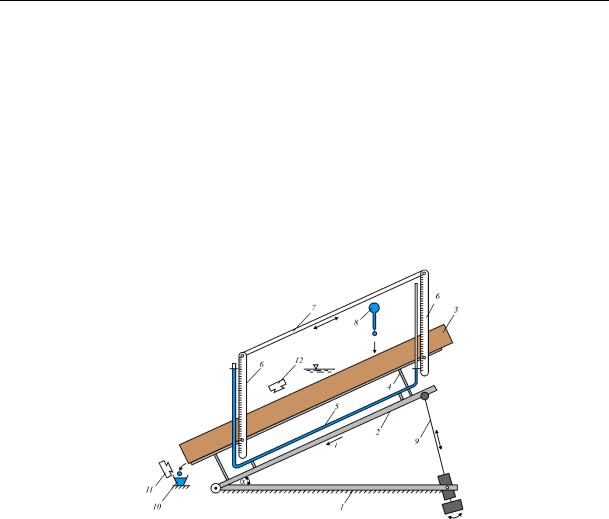
At the Scientific Research University of the Moscow State Architectural University a structure of a compact test stand was designed as an open tray for determining the water-repellent property of materials of protective coating [2]. Dynamic studies were performed on a special stand with the length of a gutter of 1 m. The simplified scheme is presented in Fig. 1.
Fig. 1. Schematic view of an experimental setup for a maximum bend of a gutter:
1 is a supporting frame; 2 is a bridge; 3 is an open gutter (tray) with a protective coating on it;
4 are bars; 5 is a system of communicating vessels; 6 are linear scales; 7 is an interface; 8 is a pipette with water; 9 is a bar of a mechanical lifting jack; 10 is a drop collector;
11, 12 are frontal and coaxial photo cameras respectively for a flow
The following were used as photo and video equipment for the configuration of the drops and a miniflow of the liquid: a digital mirror photo camera Sony-550 fitted with a system of macrorings Kenko Extension Tube as a continuous multiframe photoshooting and a digital camera Sony (model HDR-CX250E). Drinking water was used as a liquid for drops and a miniflow on the stand. Geometric and hydraulic characteristics of the miniflow formed as a certain mass (critical for a flow to start) of liquid in the open tray for different bends caused by special mechanical lifting jacks controlled by a system of communicating pipes were investigated in the stand under dynamic conditions.
34
Issue № 3 (39), 2018 |
ISSN 2542-0526 |
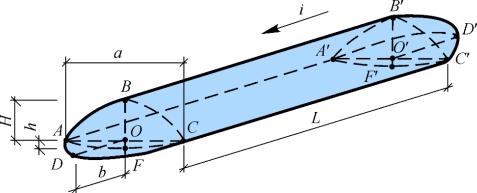
A general view of the miniflow at a certain bend i of the working surface is in Fig. 2. The head and tail of the miniflow are presented as a volume structure (half of a ball segment) АВСDА and А’В’С’D’А’ respectively. Their projections onto a vertical plane can be depicted as a lense (part of a circle). The experiments involved frontal and coaxial photo and video shooting and determining geometric sizes of a miniflow, mathematical description of contours and elements of the miniflow: the heights of the upper Н and lower lenses h, equations of the upper lens and a tangential at the intersection with a horizontal plane, edge angles α, areas of the lenses S (e.g., for the upper lens Sвер = 2aH / 3) and other parameters.
Fig. 2. Axonometric scheme of a miniflow forming as a result of a flow of a critical volume of a liquid along a tip gutter:
a, L are the average width and length of a compact part of the miniflow respectively;
Н, h are the heights of the upper and lower lenses respectively; b is the height of a half of a ball segment of the head of the miniflow; АFC, АА`C`C are soaked perimeter and surface of a compact part of the miniflow (S, сm) respectively; i is the bend of the gutter
Studies of water-repellent property were performed on the most common materials for protective coating of pipes: polypropylene, polymer hosepipe manufactured by foreign companies Per Aarsleff (Denmark) and Wawin (Holland), thin protective films by “3М” (USA), etc. Besides, the water-repellent property of the coating SmartSurface developed by the company FUJIFILMHUNT (Belgium) which is water-repellent was investigated.
As a mechanism for calculating geometric and hydraulic parameters using a relevant algorithm as well as the water-repellent property a specially designed software [4] was employed. The results of automatic calculation were an immediate output in Microsoft Word.
The technology OLE (Object Linked and Embedding) developed by the company Microsoft was used [1].
35

Russian Journal of Building Construction and Architecture
2. Results and discussion of the study of the water-repellent property. As an example Fig. 3 presents fragments of the frontal and coaxial shooting of the miniflow on the gutter covered in the protective coating “3М”.
Fig. 3. Some fragments of the frontal (on the left) and coaxial (on the right) photos
The analysis of the photos in Fig. 3 shows that according to the edge angle, this coating can be estimated as water-retentive as the edge angle (as an angle between a tangent to a drop surface and soaked with a surface where the top of an angle is in the soaking line) is around 450 (Table 1). A degree of water retention was determined using a relative water retention coefficient Kотн:
Kотн Sвер ,
(Sсм)*i
where Sвер is the area of the upper lens (АВСОA), mm2; Sсм is the area of soaking of the surface of the gutter (АА`C`C) with the compact part L of the miniflow along the width.
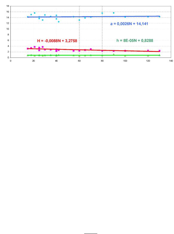
Of the most particular interest are natural experiments with a coating Smart Surface where the dependencies of the width of a flow а, heights Н of the upper and h of the lower lenses on the mass N of the miniflow in wide ranges of the bend i of the gutter that varied from 0.01 to 0.11. As for the changes in such geometric parameters as the average width of the liquid mass а and height h of the upper lens in the investigated range of the liquid mass of the lower N, we can assume they remain almost the same and a compensation in an increase in the mass N coming into the gutter affects the length L of the compact part of the miniflow as it is on the rise. In its turn, the character of change Н = f(N) shows that for small N the height H is larger than for large N, i.е. the larger the mass N of the miniflow is, the smaller the height Н of the upper lens is. The reason is a sort of “leveling” of the height H due to changes in the average length L of the compact part of the miniflow, which can be described as an evolution of the miniflow as its width is on the rise. The edge angle was about 780, which allowed a high degree of water retention of the coating to be proved.
36
Issue № 3 (39), 2018 |
ISSN 2542-0526 |
Width a, heights H and h, mm
Mass of the miniflow in drops N, drops
Fig. 4. Graphs of the dependence of the parameters of the width а, heights H and h on the mass of the miniflow N in a wide range of the bend i of the gutter
The analysis of the dependencies a = f(N), Н = f(N) and h = f(N) indicate that the experiments to determine a degree of water retention of the investigated materials in the stand can be conducted at any bend of the gutter with a possibility of the formation of a relatively stable length L of the compact part of the miniflow and smaller time costs.
Using the geometric sizes and average speeds of the miniflow obtained during the experiment by means of an automated calculation the entire range of necessary hydraulic parameters of the investigated protective coatings resulting in the roughness coefficient of the corresponding protective coating n.
As an example Table 1 shows the results of the studies of water retention of two coatings (polypropylene film and coating by the company “3M’) as experimental data, calculated geometric parameters of the miniflow and hydraulic characteristics.
The algorithm of calculating the hydraulic indices is as follows: the filling (h/d) and the soaked perimeter (the length of the arch AFC) of the miniflow; the average hydraulic radius R; the speed of the miniflow V as particular of dividing the path P of the head of the miniflow over the time Т fixed with a stopwatch; the Chezy coefficient C depending on the hydraulic radius R, the speed V and the bend i given by the formula
C RiV 0.5 ,
as well as the coefficient of a relative roughness n using the Manning formula:
C 1n R16 .
37

Russian Journal of Building Construction and Architecture
Таble 1
Results of the calculation of the geometric parameters and hydraulic characteristics of the miniflow in the tray with the diameter d = 130 mm at the bend i = 0.11
Parameter |
|
Маterial |
|
|
|
|
|
|
Polypropylene |
|
Film by 3М |
|
|
|
|
Area АВCOA of the upper lens Sвер, mm2 |
25.62 |
|
25.33 |
Soaked perimeter AFC, mm |
14.56 |
|
11.89 |
|
|
|
|
Soaked surface АА`C`C Sсм, mm2 |
218.539 |
|
214.187 |
Relative water retention index Котн |
1.065 |
|
1.075 |
Edge angle α0 |
36012’ |
|
15.09 |
Calculated value Lрасч, mm |
450 18’ |
|
20.07 |
Average hydraulic radius R, mm |
0.38 |
|
0.34 |
|
|
|
|
Path of the miniflow, P, mm |
90 |
|
83 |
|
|
|
|
Time of the path Т, sec |
5 |
|
5 |
|
|
|
|
Average speed of the miniflow V, mm/sec |
18 |
|
16.6 |
|
|
|
|
Chezy coefficient С |
64.52 |
|
88.09 |
|
|
|
|
Coefficient of the relative roughness n |
0.0132 |
|
0.0096 |
|
|
|
|
According to the suggested method of calculating the roughness coefficient n using the Manning formula for polypropylene based on the results of the experiments was n = 0.0132 for the relative water retention coefficient Котн = 1.0655. For other protective coatings it varied from 0.009––0.0098 and the coefficients of a relative water retention from 1.075––1.098 respectively (for the coating Smart Surface –– 1.098). Hence the correlation was found between the coefficients of a relative water retention and roughness: the higher the water retention is, the smaller the roughness of a material is. The resulting calculation information can be regarded as a tool for a designer in evaluating the hydraulic characteristics of a corresponding type of a protective coating.
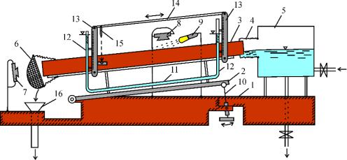
3. Меthods and equipment for studying microturbulence of a liquid flow in open trays in order to enhance its transporting capacity for transmitting weighed particles. In order to examine vortex formation (microturbulence) in open trays with a structured surface, a special hydraulic stand was designed (Fig. 5) [3].
Patterns of stirring-up and motion of sand of different fractions in a wide consumption range (flow rates) were recorded in the stand using the light-and-shadow effect by means of video and photo equipment. 10 types of group obstacles located at the bottom of the tray with the
38
Issue № 3 (39), 2018 |
ISSN 2542-0526 |
diameter of 130 mm on both sides of its axis were used as ribbed surfaces. The obstacles were from polymer materials that were slightly rough. The fillings in the tray at this point of the experiment were assumed to be comparable with the diameter of the largest sand fractions (of about 2––3 mm).
Fig. 5. Schematic view of the experimental stand for studying turbulence and transporting capacity of a liquid flow by means of optical tools:
1 is a motionless frame; 2 is a mobile platform; 3 is an open tray; 4 is a rubber corrugated nozzle; 5 is an accumulating vessel for liquid; 6 is a removable screen trap for foreign disperse inclusions; 7, 8 are photo cameras for frontal and coaxial shooting respectively; 9 is a source of light radiation; 10 is a mechanical lifting jack; 11 is a water pipeline; 12 are flexible transparent communicating pipes; 13 are mobile linear scales; 14 is a stand планка; is a laser rod; 16 is a receiving scaling vessel
4. Results and discussion of the study of the transporting capacity of the pipelines. As an example below are the results of search experiments of visual and hydraulic studies of “tree”-shaped obstacles, i.e. rectangular bars with the height of 2 mm located on the water repellent surface Smart Surface and located at the angle of 300 in relation to the tray axis.
Table 2 and 3 shows the dynamics of washing-out of sand impurities with the fraction diameters of 2.5––3.0 and 0.1––0.3 mm respectively.
Analyzing the data in Table 2 and 3, we assume that effective washing-out of sand particles at the rates similar to self-cleaning ones at the fraction diameter of 2.5––3.0 mm: in the tray there is intense washing-out of the sand with water masses that is transported. The use of the light- and-shadow effect indicates that there is a flow turbulization when flow rates are on the rise. It is not quite the case for a small sand fraction (0.1––0.3 mm): the sand is not removed entirely but in portions and slowly towards the flow. The character of motion is chaotic with a flow of a sand mass next to water retentive slopes with swells of sand shifting to the center of the tray.
39

Таble 2
Таble 3
Dynamics of changes in the pattern of washing-out of the pollutions with the fraction diameter of 0.1––0.3 mm depending on the flow rate
Pattern of microturbulence zones and washing-out of the sand impurities Water flow rate, m/seс 0.2––0.3
0.4––0.5
0.6––0.7
40