

3513
.pdfIssue № 3 (39), 2018 |
ISSN 2542-0526 |
3.Granev V. V., Kodysh E. N. Razrabotka i aktualizatsiya normativnykh dokumentov po proektirovaniyu i stroitel'stvu promyshlennykh i grazhdanskikh zdanii [Development and updating of normative documents on design and construction of industrial and civil buildings]. Promyshlennoe i grazhdanskoe stroitel'stvo, 2014, no. 7, pp. 9—12.
4.Emel'yanov R. E. Metody povysheniya nadezhnosti organizatsionno-tekhnologicheskikh reshe-nii pri stroitel'stve i rekonstruktsii transportnykh ob"ektov s uchetom riskov. Diss. kand. tekh. nauk [Methods of improving the reliability of organizational and technological solutions in the construction and reconstruction of transport facilities taking into account the risks. Cand. eng. sci. diss.]. Moscow, 2004. 304 p.
5.Zharov Ya. V. Prinyatie organizatsionno-tekhnologicheskikh reshenii v stroitel'stve na osnove tekhnologii mnogomernogo modelirovaniya. Diss. kand. tekh. nauk [Making organizational and technological decisions in construction based on multi-dimensional modeling technology. Cand. eng. sci. diss.]. Moscow, 2014. 143 p.
6.Kerimov F. Yu. Povyshenie organizatsionno-tekhnologicheskoi nadezhnosti podgotovki stroitel'nogo proizvodstva v usloviyakh snizheniya resursnogo obespecheniya. Diss. d-ra tekhn. nauk [Increase of organizational and technological reliability of preparation of construction production in the conditions of reduction of resource provision. Dr. eng. sci. diss]. Moscow, 2005. 336 p.
7.Legostaeva O. A. Sovershenstvovanie organizatsionno-tekhnologicheskoi nadezhnosti stroi-tel'nykh protsessov v inzhenernykh proektakh. Diss. kand. tekh. nauk [Improvement of organizational and technological reliability of construction processes in engineering projects. Cand. eng. sci. diss.]. Novosibirsk, 2007. 203 p.
8.M. Yu. Matveev, Sborshchikov S. B., Sborshchikova M. N. Razvitie sistemy normirovaniya truda za rubezhom [Development of the system of labor regulation abroad]. Vestnik MGSU, 2011, vol. 2, no. 3, pp. 68—74.
9.Morozov D. V. Metody opredeleniya nadezhnosti organizatsionno-tekhnologicheskikh reshenii pri stroitel'stve i rekonstruktsii zheleznyi dorog s pozitsii sistemotekhniki. Diss. kand. tekh. nauk [Methods for determining the reliability of organizational and technological solutions in the construction and reconstruction of Railways from the standpoint of systems engineering. Cand. eng. sci. diss.]. Moscow, 2005. 127 p.
10.Mukhametzyanov Z. R. Kontseptual'naya osnova povysheniya effektivnosti organizatsionnykh reshenii dlya realizatsii kalendarnogo plana stroitel'stva [Conceptual basis for improving the efficiency of organizational solutions for the implementation of the construction schedule]. Privolzhskii nauchnyi zhurnal, 2015, no. 4, pp. 90—96.
11.Mukhametzyanov Z. R. Metodika rascheta kolichestvennoi otsenki tekhnologicheskikh svyazei me-zhdu stroitel'nymi protsessami [The method of calculating the quantitative estimation of technological connections between building processes]. Nauchnyi vestnik Voronezhskogo GASU. Stroitel'stvo i arkhitektura, 2014, no. 2 (34), pp. 44—50.
12.Mukhametzyanov Z. R., Gusev E. V., Razyapov R. V. Formirovanie teoreticheskikh i metodologicheskikh osnov povysheniya effektivnosti organizatsionnykh reshenii dlya tselei kalendarnogo planirovaniya [Formation of theoretical and methodological bases of increase of efficiency of the organizational decisions for the purpose of scheduling]. Promyshlennoe i grazhdanskoe stroitel'stvo, 2015, no. 12, pp. 68—72.
13.Potapova I. V. Sovershenstvovanie metodov kalendarnogo planirovaniya transportnogo stroitel'stva (na primere mostostroeniya). Diss. kand. tekh. nauk [Improving methods of scheduling transport construction (for example, bridge building). Cand. eng. sci. diss.]. Khabarovsk, 2009. 210 p.
91

Russian Journal of Building Construction and Architecture
14.Sborshchikov S. B., Markova I. M. Novye organizatsionnye skhemy realizatsii investitsionno-stroitel'nykh proektov v energeticheskom sektore [New organizational schemes of implementation of investment and construction projects in the energy sector]. Vestnik MGSU, 2010, vol. 5, no. 4, pp. 335—340.
15.Sborshchikov S. B. Teoreticheskie zakonomernosti i osobennosti organizatsii vozdeistvii na investitsionnostroitel'nuyu deyatel'nost' [Theoretical regularities and features of the organization of impacts on investment and construction activities]. Vestnik MGSU, 2009, no. 2, pp. 183—187.
16.Shirshikov B. V., Slavin A. M., Stepanova V. S., Mikheev S. O. Minimizatsiya prodolzhitel'nosti vozvedeniya ob"ektov na osnove ispol'-zovaniya informatsionno-dinamicheskikh setevykh modelei [Minimizing the duration of construction of objects based on the use of information-dynamic network models]. Promyshlennoe i grazhdanskoe stroitel'stvo, 2016, no. 2, pp. 70—75.
17.Farag M. A. A Bridge between increasing reliability and reducing variability in construction work flow: A fuzzy-based sizing buffer model. Journal of Advanced Management Science, 2014, vol. 2, no. 4, pp. 287—294.
18.Mukhametzyanov Z. R., Melkumov V. N. Calculation method of quantitative estimation of technological connections between building processes. Scientific Herald of the Voronezh State University of Architecture and Civil Engineering. Construction and Architecture, 2014, no. 4 (24), pp. 38—47.
19.Nan C., Sansivini G., Kröger W. Building an Integrated Metric for Quantifying the Resilience of Interdependent Infrastructure Systems. International Conference on Critical Information Infrastructures Security. Springer International Publishing, 2014, pp. 159—171.
20.Sarhan S., Fox A. Barriers to implementing lean construction in the UK construction industry. The Built & Human Environment Review, 2013, vol. 6, no. 1, pp. 1—17.
21.Wu L. Improving efficiency and reliability of building systems using machine learning and automated online evaluation. Systems, Applications and Technology Conference (LISAT). Long Island, IEEE, 2012, pp. 1—6.
22.Wu S., Clements-Croome D. J., Fairey V., Neale K., Albany B., Sidhu J., Desmond D. Reliability in the whole life cycle of building systems. Engineering, Construction and Architectural Management, 2006, Т. 13, no. 2, pp. 136—153.
23.Seredin P. V., Ternovaya V. E., Glotov A. V., Len'shin A. S., Arsent'ev I. N., Vinokurov D. A., Tarasov I. S., Leiste5 H., Prutskij T. X-ray diffraction studies of heterostructures based on solid solutions AlxGa1 ––
xAsyP1 –– y: Si. Physics of the Solid State, 2013, vol. 55, iss. 10, pp. 2161––2164. doi: 10.1134/S1063783413100296.
92

Issue № 3 (39), 2018 |
ISSN 2542-0526 |
DESIGNING AND CONSTRUCTION OF ROADS,SUBWAYS,
AIRFIELDS,BRIDGES AND TRANSPORT TUNNELS
UDC 624.21
А. N. Yashnov1, S. Yu. Polyakov2
EXPERIMENTAL DETERMINATION OF STRESS-STRAIN STATE
OF ASPHALT PAVEMENT ON METAL BRIDGES
Siberian Transport University
Russian Federation, Novosibirsk
1PhD in Engineering, Assoс. Prof. of the Dept. of Bridge Construction, tel.: 8-383-328-04-90, e-mail: yan@stu.ru
2PhD student of the Dept. of Bridge Construction, tel.: 8-952-918-64-28, e-mail: sergey19920@mail.ru
Statement of the problem. Currently bridge surfacings are not designed but assigned with no consideration of the features of operation of an artificial structure. This might be the reason why bridge pavement has a short service life. In order to calculate bridge surfacings, it is necessary to know its stress-strain state under the action of a moving load that depends on its material and mechanical characteristics. This article is devoted to a practical application of a model for calculating a asphalt deformation modulus and Poisson's ratio.
Results. The data obtained as part of some experiments on artificial structures to determine the stressstrain of surfacings indicate that the resulting assumptions meet the actual operating conditions. Conclusions. The dependences for determining a deformation modulus and Poisson’s ratio of asphalt concrete, which would allow them to be applied for developing the methods for calculating an asphalt concrete on an orthotropic steel decks of metal bridges.
Keywords: bridge, superstructure, orthotropic steel deck, stress-strain state, surfacing, asphalt, modulus of deformation, Poisson’s ratio.
Introduction. Construction parameters of elements perceiving efforts of any loads are generally specified based on calculation results to identify stress-strains of some structures. E.g., this is the case for designing bearing elements of span structures of bridges as well as of non-rigid surfacing. One of the loads here are transport vehicles and if a surfacing itself is a bearing element, on bridges it serves only to transmit an external impact onto the bearing elements of a highway and then onto the main beams/girders without increasing the bearing capacity of a structure.
© Yashnov А. N., Polyakov S. Yu., 2018
93

Russian Journal of Building Construction and Architecture
Based on the fact that it is necessary to calculate surfacing according to a moving load, it leaves no doubt. The result of many years of studies and thus improvement of the relevant regulations is currently Industry Road Norms (IRN) 218.046-01 “Designing Non-Rigid Surfacing”.
It is not quite the case for bridges. Since highway surfacing here is not an immediate bearing element, it does not appear absolutely necessary to calculate it. It is proved in the regulations in Set of Rules (СП) 35.13330.2011 “Bridges and Pipes” prescribing that the parameters of a surfacig should be specified according to a structure regardless of its operational features on a span. However, highway surfacing perceives an immediate transport load and is deformed along with an an orthotropic or ferroconcrete plate of a highway. If some of the parameters of asphalt concrete that is typical of its stress-strain is over its limit, there is a defect of a material, which leads to degradation of operational characteristics of a structure and further repairs. One of the common defects of surfacing on an orthotropic plate of span structures of metal bridges are cracks at the largest local rigidity points of a structure (over the walls of main and transverse beams). This is what occurred in the bridges over the Mzymta River (Fig. 1) and some other structures [2, 10, 19––21]. In a surfacing on a ferroconcrete plate of a highway there were no such cracks due to its considerably large rigidity. Therefore it is only of interest to examine highway surfacing on an orthotropic plate.
Fig. 1. Transverse cracks in a surfacing over the walls of main beams of the bridges through the Mzymta River
We believe that this defect was caused by excessively large transverse stretching strains in asphalt concrete compared to the strength of the material. It does not currently appear easy to identify the stress-strain of the surfacing as there are no legal regulations for the methods of calculating highway surfacing that is proved with experimental data. Therefore determining the stress-strain of a surfacing on an orthotropic plate of bridge spans is an important issue that has to be addressed in order to develop the methods to result in a defect-free life cycle of highway surfacing.
94
Issue № 3 (39), 2018 |
ISSN 2542-0526 |
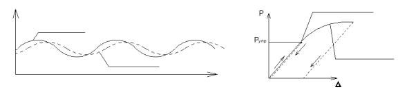
1. Calculation model for determining the characteristics of asphalt concrete. Asphalt concrete is an elastic-viscoplastic material, i.e. deformation and an applied load depend on the temperature t, time of load application τ and stress-strain of a material (Fig. 2).
а) viscoplatic deformation |
|
|
b) effort-deformation ratio |
||||||||
|
|
|
|
|
|
|
|
|
|
|
|
|
|
|
|
|
|
|
|
|
Elastic deformation |
||
|
|
Amplitude |
|
|
|
|
|
|
|
||
|
|
|
|
|
|
|
|
|
|
|
|
|
|
|
P |
|
|
|
|
||||
|
|
|
|
|
|
|
|
|
|
|
|
|
|
Strains |
|
|
|
|
|
|
|
||
|
|
|
|
|
|
|
|
|
|
||
|
|
|
|
|
|
|
|
|
|
|
|
|
|
|
|
|
|
|
Pупр |
||||
|
|
|
|
Deformations |
|||||||
|
|
|
|
|
|
|
|
|
|
Plastic deformation |
|
|
|
|
|
|
|
|
|||||
|
|
|
|
|
Time |
||||||
Fig. 2. Elastic-viscoplastic deformation of asphalt concrete
In order to determine the stress-strain of asphalt concrete under a load, it is necessary to know its deformation modulus E and Poisson coefficient µ that depend on the temperature as well as time of loading. However, in the current regulations IRN (ОДН) 218.046-01 the deformation modulus of a material for calculating compressive stretching are specified only at t = 0 0С and τ = 0.1 с. Poisson coefficient is not regulated. Therefore in calculating it becomes challenging to identify the above characteristics in all possible ranges of temperature changes and times of loading.
The character of deformation of asphalt concrete in different conditions is the subject of study by many scholars in this country and around the world. They often have their own view on the deformation mechanism of the material, which led to diversity of calculation models for calculating the deformation modulus.
Some of such dependencies have been investigated and analyzed [17, 18] resulting in the decision to employ a model by D. Christensen and the co-authors used along with the formula for determining a modulus of deformation (or rigidity as agreed on by the authors) of bitumen obtained by B. S. Radovskiy and B. B. Teltayev [11]. Let us look at it in more detail.
Asphalt concrete is a composite material. Thus according to the rule of mixtures by Reiss and Voigt its deformation modulus [11] first of all ranges between those of the components making it up and secondly depends on the volume of a mixture taken up by each component. The character of the connection at the contact of a matrix and inclusions also has a considerable influence on the deformation modulus: if this connection is weak, tangential strains along the contact are not transmitted and the components are thus deformed “sequentially”, i.e. transverse deformations of the components of a mixture are summed (which can apply for asphalt concrete at high temperatures). If this connection is significant, the reverse happens.
95

Russian Journal of Building Construction and Architecture
In 1962 T. Hirsch set forth a formula for determining the deformation modulus of cement concrete based on the rule of mixtures by Reiss and Voigt considering the effect of the connection at the contact of inclusions and matrix [11]:
1 |
|
|
k |
|
|
|
|
c2 |
|
|
|
|||
|
|
|
|
c1 |
|
|
|
|
||||||
|
|
|
|
|
|
|
(1 k) |
|
|
|
|
|
, |
(1) |
Е |
с |
E c |
E |
c |
2 |
E |
E |
2 |
||||||
|
1 1 |
2 |
|
1 |
|
|
|
|
|
|||||
where Ес is a deformation modulus of a composite material; Е1 is a deformation modulus of the first component; Е2 is a deformation modulus of the second component; с1 is a volumetric proportion of the first component in a mixture; с2 is a volumetric proportion of the second component in a mixture; k is an empirical component ranging from 0 to 1 that characterizes the connection at the contact of a matrix and filler that show how close a deformation modulus of a composite material is to the lower or upper boundary of a possible range. The dependence by T. Hirsch was improved for asphalt concrete by D. Christensen, T. Pellinen and R. Bonaquist [11]. The empirical coefficient k is presented as the contact function Pc that characterizes the contribution of each component into the deformation modulus of asphalt concrete:
|
|
|
E |
VFA P1 |
|
|
|
P |
|
|
|
||
P |
|
0 |
|
b VMA |
, |
(2) |
c |
P |
|
VFA P1 |
|
||
|
E |
|
|
|
||
|
2 |
|
|
b VMA |
|
|
where P0, P1, P2 are empirical coefficients; Eb is a rigidity modulus of a binder; VMA is the porosity of a mineral material (in units); VFA is the proportion of pores between the grains filled with a binder.
The formula itself for calculating a deformation modulus of asphalt concrete is as follows:
Emix Pc [Eagg (1 VMA) Eb VMA VFA] |
|
|
1 Pc |
, |
(3) |
||||
(1 |
VMA) |
|
VMA |
|
|||||
|
|
|
|||||||
|
|
E |
agg |
E VFA |
|
|
|||
|
|
|
|
|
|||||
|
|
|
|
b |
|
|
|||
where Eagg is a deformation modulus of a stone material.
The deformation modulus of a binder can be determined by means of a dependence identified by B. B. Teltayev and B. S. Radovskiy [11]:
|
|
|
|
|
|
|
|
1 |
1 |
|
|
|
|
|
E |
t b |
|
b |
|
|
|||
|
|
|
|
|
|||||||
E(t) E |
1 |
|
g |
|
|
|
|
|
|
, |
(4) |
3η |
|
|
|
||||||||
|
g |
|
|
|
|
|
|
|
|
||
|
|
|
|
|
|
|
|
|
|
|
|
where Eg is a rigidity modulus of a binder in a glass condition; t is time of a load impact; η is the viscosity of bitumen depending on the temperature and time of a load impact; b is the parameter depending on the penetration index of bitumen.
96

Issue № 3 (39), 2018 |
ISSN 2542-0526 |
Strictly speaking, E(t) in the dependence (4) is not a modulus of rigidity but of relaxation of bitumen as it is inserted into the formula (3) Emix which becomes the modulus of relaxation of asphalt concrete. ановится However, in order to avoid confusion, the above terminology is used. Since the above calculation model reflects the character of the interaction of the components of asphalt concrete using the contact function Pc, the calculated values of the deformation modulus of this composite material indirectly characterize the ratio between longitudinal and transverse deformations of a mixture (i.e. the higher Emix is, the stronger at the connection is between the components and the transverse deformations are thus smaller). Therefore between the values of Emix and µ there should be a correlation dependence that can be specified according to the mechanical and empirical method of designing surfacing [9, 24]:
μ 0.15 |
0.35 |
, |
(5) |
1 e 12.452 2.291lgE* |
where E* is a complex modulus of asphalt concrete, psi (1 psi = 0.00689 МPа) which can be the values of the deformation modulus Emix.
2. Experimental studies of the stress-strain of asphalt concrete. In order to evaluate the correspondence of the above calculation model to the actual character of deformation of asphalt concrete, it is essential to test it in practice. As an option, the stress-strain of road surfacing in artificial structures can be identified under the impact of actual moving vehicles as we did for the current study.
The experiments were conducted in four bridge crossings:
––№ 1 is a steel ferroconcrete pipeway in Krasnoyarsk (Fig. 3а);
––№ 2 is a bridge through the Tobol River in Tuymen region (Fig. 3b);
––№ 3 is a bridge through the Pregolya River in Kaliningrad (Fig. 3c);
––№ 4 is a bridge through the Kondoma River in Kemerovo region (Fig. 3d).
The main bearing elements of the investigated artificial structures are presented with metal solid wall beams of a double-tee and box section with the spans from 14.8 to 126 m. The bearing structures of the roadway are ferroconcrete or orthotropic plates with band/box transverse ribs. The structure of the roadway is made up of a hydro insulation layer + concrete of different types (dense, stone mastic, cast).
At the time of the experiments all the structures were at the final stages of construction, thus there were not any defects in the surfacing. Therefore the areas for setting up the measurement equipment were selected based on the experience of the operation of other bridges as well as the results of the preliminary calculations. The sensor reading the transverse deformations of the upper fiber of an asphalt concrete surfacing were placed over the walls of the main beams.
97

Russian Journal of Building Construction and Architecture
а) |
b) |
c) |
d) |
Fig. 3. Structures where the stress-strain of a road surfacing was experimentally identified
As a testing load single dump trucks were presented with the full mass from 27 to 42 tons. The principal scheme of the vehicle used for loading the road surfacing is presented in Fig. 4.
|
1.3…1.4 m |
|
|
2.8…3.7 m |
|
|
|
|
|
|
|
|
|
|
|
|
|
|
|
|
|
|
6.0…8.5 ton-force |
11…17 ton-force |
|
11…17 ton-force |
|||||
|
|
|
|||||
Vehicle with the test load
Fig. 4. Principal scheme of the test load
98
Issue № 3 (39), 2018 |
ISSN 2542-0526 |
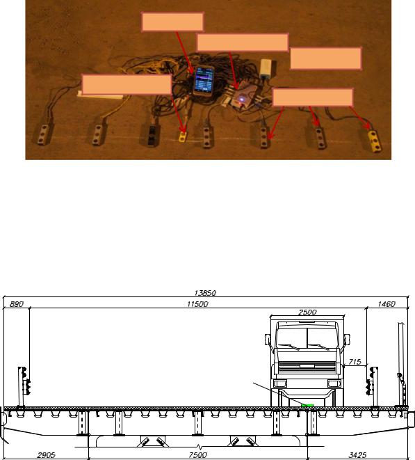
The parameters of the stress-strain of asphalt concrete were fixed using a measuring multifunctional complex “Tensor MS” developed by the Scientific Research Laboratory “Mosty” of the Siberian State Transport University (a certificate of the Federal Agency in Technical Regulation and Metrology for Measurement Equipment RU.C.34.007.A № 32603/1, valid till November, 22, 2018). Fig. 5 shows a measurement complex set up in the bridge roadway and ready to operate.
Smartphone
Measurement block
 Accumulator
Temperature sensor
Tensor sensors
Fig. 5. Measurement complex “Tensor MS” in the operating condition
Throughout the course of the tests, a few options of loading the road surfacing: overpasses over the controlled sections with different speeds as well as stops over them different in time. The schemes for placing the dump truck in the overpass as well as the measurement equipment are shown in Fig. 6.
Tensor sensors |
of the Tensor MS system |
Fig. 6a. Example of placing the test load and measurement equipment in the roadway: scheme of placing the load and equipment in a transverse direction (the bridge through the Tobol River)
99
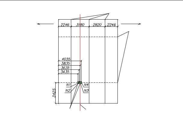
Russian Journal of Building Construction and Architecture |
|
Block Б58 |
Walls of transverse beams |
|
|
Support 5 |
Support 10 |
|
Walls of the main beams |
Tensor sensors |
|
of the Tensor MS system |
Testing section |
Fig. 6b. Example of placing the test load and measurement equipment in the roadway: scheme of placing the measurement equipment in the plan (the bridge through the Tobol River)
Based on the diversity of factors influencing the stress-strain of a road surfacing, a calculation model for mechanical characteristics of asphalt concrete should be tested in a maximum range of changing parameters, which was taken into account during the tests (Table 1).
|
|
|
|
Таble 1 |
|
|
The parameters changing during the experiments |
|
|||
|
|
|
|
|
|
Parameter |
|
Tested structure |
|
||
|
|
|
|
||
|
№ 1 (Krasnoyarsk) |
№ 2 (Tobol River) |
№ 3 (Pregolya River) |
№ 4 (Kondoma River) |
|
|
|
|
|
|
|
Type of |
Ferroconcrete plate |
Оrthotropic plate with |
Orthotropic plate with |
Orthotropic plate with |
|
a roadway |
with the thickness of |
box stringers |
band stringers |
box stringers |
|
240 mm |
|||||
|
|
|
|
||
|
|
|
|
|
|
|
|
Hydroinsulation |
Hydroinsulation |
|
|
|
Hydroinsulation |
“Technoelastmost C” + |
|
||
|
“Technoelastmost C” + |
Hydroinsulation |
|||
|
“Technoelastmost C” + |
+ dense asphalt con- |
+ cast asphalt concrete |
“Mostoplast” + cast |
|
Structure of |
+ dense asphalt con- |
crete of type B of Class |
|||
of Type I with the |
asphalt concrete of |
||||
a roadway |
crete of type B of Class |
I with the thickness |
thickness 50 mm on a |
Type I with the thick- |
|
|
I with the thickness |
60 mm + stone mastic |
movable and 80 mm on |
ness 105 mm |
|
|
110 mm |
asphalt –15 with the |
stationary spans |
|
|
|
|
thickness 50 mm |
|
||
|
|
|
|
||
|
|
|
|
|
|
100