

755
.pdf178 |
3G Evolution: HSPA and LTE for Mobile Broadband |
DPCH transmit power at the serving HS-DSCH cell does not necessarily reflect the perceived UE channel quality. Hence, more frequent UE quality reports are typically required in soft handover scenarios.
9.3.7Downlink control signaling: HS-SCCH
The HS-SCCH, sometimes referred to as the shared control channel, is a shared downlink physical channel that carries control signaling information needed for a UE to be able to properly despread, demodulate and decode the HS-DSCH.
In each 2 ms interval corresponding to one HS-DSCH TTI, one HS-SCCH carries physical-layer signaling to a single UE. As HSDPA supports HS-DSCH transmission to multiple users in parallel by means of code multiplexing, see Section 9.1.1, multiple HS-SCCH may be needed in a cell. According to the specification, a UE should be able to decode four HS-SCCHs in parallel. However, more than four HS-SCCHs can be configured within a cell, although the need for this is rare.
HS-SCCH uses a spreading factor of 128 and has a time structure based on a subframe of length 2 ms which is the same length as the HS-DSCH TTI. The following information is carried on the HS-SCCH:
•The HS-DSCH transport format, consisting of:
–HS-DSCH channelization-code set [7 bits]
–HS-DSCH modulation scheme, QPSK/16QAM [1 bit]
–HS-DSCH transport-block size information [6 bits].
•Hybrid-ARQ-related information, consisting of:
–hybrid-ARQ process number [3 bits]
–redundancy version [3 bits]
–new-data indicator [1 bit].
•A UE ID that identifies the UE for which the HS-SCCH information is intended [16 bits]. As will be described below, the UE ID is not explicitly transmitted but implicitly included in the CRC calculation and HS-SCCH channel coding.
As described in Section 9.2.4, the HS-DSCH transport block can take 1 out of 254 different sizes. Each combination of channelization-code-set size and modulation scheme corresponds to a subset of these transport-block sizes, where each subset consists of 63 possible transport-block sizes. The 6-bit ‘HS-DSCH transport-block size information’ indicates which out of the 63 possible transport-block sizes is actually used for the HS-DSCH transmission in the corresponding TTI. The transport-block sizes have been defined to make full use of code rates ranging from 1/3 to 1 for initial transmissions. For retransmissions, instantaneous code rates larger than one can be achieved by indicating ‘the transport-block size is identical to the previous transmission in this hybrid-ARQ process.’ This is indicated setting
High-Speed Downlink Packet Access |
179 |
the ‘HS-DSCH transport-block size information’ field to 111111. This is useful for additional scheduling flexibility, for example to retransmit only a small amount of parity bit in case the latest CQI report indicates the UE ‘almost’ was able to decode the original transmission.
Requirements on when different parts of the HS-SCCH information need to be available to the UE has affected the detailed structure of the HS-SCCH channel coding and physical-channel mapping. For UE complexity reasons, it is beneficial if the channelization-code set is known to the UE prior to the start of the HS-DSCH transmission. Otherwise, the UE would have to buffer the received signal on a sub-chip level prior to despreading or, alternatively, despread all potential HS-DSCH codes up to the maximum of 15 codes. Knowing the modulation scheme prior to the HS-DSCH subframe is also preferred as it allows for ‘on-the-fly’ demodulation. On the other hand, the transport-block size and the hybrid-ARQ- related information are only needed at HS-DSCH decoding/soft combining, which can anyway not start until the end of the HS-DSCH TTI. Thus, the HS-SCCH information is split into two parts:
1.Part 1 consisting of channelization-code set and modulation scheme [total of 8 bits].
2.Part 2 consisting of transport-block size and hybrid-ARQ-related parameters [total of 13 bits].
The HS-SCCH coding, physical-channel mapping and timing relation to the HS-DSCH transmission is illustrated in Figure 9.22. The HS-DSCH channel coding is based on rate-1/3 convolutional coding, carried out separately for part 1 and part 2. Part 1 is coded and rate matched to 40 bits to fit into the first slot of the HS-SCCH subframe. Before mapping to the physical channel, the coded part 1 is scrambled by a 40 bits UE-specific bit sequence. The sequence is derived from the 16 bits UE ID using rate-1/2 convolutional coding followed by puncturing. With the scheme of Figure 9.22, the part 1 information can be decoded after one slot of the HS-SCCH subframe. Furthermore, in case of more than one HS-SCCH, the UE can find the correct HS-SCCH from the soft metric of the channel decoder already after the first slot. One possible way for the UE to utilize the soft metric for determining which (if any) of the multiple HS-SCCHs that carries control information for the UE is to form the log-likelihood ratio between the most likely code word and the second most likely code word for each HS-SCCH. The HS-SCCH with the largest ratio is likely to be intended for the UE and can be selected for further decoding of the part-2 information.
Part 2 is coded and rate matched to 80 bits to fit into the second and third slot of the HS-SCCH. Part 2 includes a UE-specific CRC for error detection. The CRC is calculated over all the information bits, both part 1 and part 2, as well as the UE

180 |
|
|
|
|
|
|
|
3G Evolution: HSPA and LTE for Mobile Broadband |
|||
|
Part 1 |
UE |
|
|
Part 2 |
||||||
codes, modulation |
identity |
TB size, hybrid-ARQ info |
|||||||||
|
|
|
|
|
|
|
|
|
|
|
|
|
|
|
|
|
|
|
|
|
|
|
|
|
|
|
|
|
|
|
|
|
|
|
|
|
|
|
|
|
|
|
|
|
UE-specific |
|
|
|
|
|
|
|
|
|
|
|
CRC |
|
|
|
|
|
|
|
|
|
|
|
|
|
|
|
|
|
|
|
|
|
|
|
|
|
|
|
R=1/3 |
|
|
|
|
|
|
|
|
|
|
|
|
|
|
|
|
|
R=1/3 |
|
|||
|
convolutional |
|
|
|
|
|
|
|
|||
|
|
|
|
|
|
|
convolutional |
|
|||
|
coding |
|
|
|
|
|
|
|
|||
|
|
|
|
|
|
|
coding |
|
|||
|
|
|
|
|
|
|
|
|
|
||
|
|
|
|
|
|
|
|
|
|
|
|
|
|
|
|
|
|
|
|
|
|
|
|
|
Puncturing |
|
|
|
|
|
|
|
|
|
|
|
|
|
|
|
|
|
Puncturing |
|
|||
|
|
|
|
|
|
|
|
|
|
||
|
|
|
|
|
|
|
|
|
|
|
|
|
|
|
|
|
|
|
|
|
|
||
|
|
|
|
|
|
|
|
|
|
|
|
|
UE-specific |
|
|
|
|
|
|
|
|
|
|
|
scrambling |
|
|
|
|
|
|
|
|
|
|
|
|
|
|
|
|
|
|
|
|
|
|
|
|
|
|
|
|
|
|
|
|
|
|
|
|
|
|
|
|
|
|
|
|
|
|
HS-SCCH |
Part 1 |
|
Part 2 |
|
|
|
|
||
|
|
Part 1 decoding time |
|
Part 2 decoding time |
|||||
|
|
|
|
|
|
|
|
|
|
|
|
|
|
|
|
|
|
|
|
HS-PDSCH |
|
|
|
|
|
HS-DSCH data |
|
|
|
|
|
|
|
|
|
|
|
|
|
Figure 9.22 HS-SCCH channel coding.
identity. The identity is not explicitly transmitted, but by including its ID when calculating the CRC at the receiver, the UE can decide whether it was the intended recipient or not. If the transmission is intended for another UE, the CRC will not check.
In case of HS-DSCH transmission to a single UE in consecutive TTIs, the UE must despread the HS-SCCH in parallel to the HS-DSCH channelization codes. To reduce the number of required despreaders, the same HS-SCCH shall be used when HS-DSCH transmission is carried out in consecutive TTI. This implies that, when simultaneously receiving HS-DSCH, the UE only needs to despread a single HS-SCCH.
In order to avoid waste of capacity, the HS-SCCH transmit power should be adjusted to what is needed to reach the intended UE. Similar information used for rate control of the HS-DSCH, for example the CQI reports, can be used to power control the HS-SCCH.
9.3.8Downlink control signaling: F-DPCH
As described in Section 9.2.1, for each UE for which HS-DSCH can be transmitted, there is also an associated downlink DPCH. In principle, if all data transmission,

High-Speed Downlink Packet Access |
|
181 |
||
|
|
One slot |
|
|
UE #1 |
DTX TPC |
DTX |
|
|
UE #2 |
DTX TPC |
DTX |
|
Same |
|
|
|
|
channelization |
|
|
|
|
code |
UE #10 |
|
|
DTX TPC |
DTX |
Figure 9.23 Fractional DPCH (F-DPCH), introduced in Release 6.
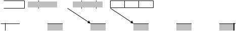
including RRC signaling, is mapped to the HS-DSCH, there is no need to carry any user data on the DPCH. Consequently, there is no need for downlink TransportFormat Combination Indicator (TFCI) or dedicated pilots on such a DPCH. In this case, the only use for the downlink DPCH in case of HS-DSCH transmission is to carry power control commands to the UE in order to adjust the uplink transmission power. This fact is exploited by the F-DPCH or fractional DPCH, introduced in Release 6 as a means to reduce the amount of downlink channelization codes used for dedicated channels. Instead of allocating one DPCH with spreading factor 256 for the sole purpose of transmitting one power control command per slot, the F-DPCH allows up to ten UEs to share a single channelization code for this purpose. In essence, the F-DPCH is a slot format supporting TPC bits only. Two TPC bits (one QPSK symbol) is transmitted in one tenth of a slot, using a spreading factor 256, and the rest of the slot remains unused. By setting the downlink timing of multiple UEs appropriately, as illustrated in Figure 9.23, up to ten UEs can then share a single channelization code. This can also be seen as time-multiplexing power control commands to several users on one channelization code.
9.3.9 Uplink control signaling: HS-DPCCH
For operation of the hybrid-ARQ protocol and to provide the NodeB with knowledge about the instantaneous downlink channel conditions, uplink control signaling is required. This signaling is carried on an additional new uplink physical channel, the HS-DPCCH, using a channelization code separate from the conventional uplink DPCCH. The use of a separate channelization code for the HS-DPCCH makes the HS-DPCCH ‘invisible’ to non-HSDPA-capable base stations and allows for the uplink being in soft handover even if not all NodeBs in the active set support HSDPA.
The HS-DPCCH uses a spreading factor of 256 and is transmitted in parallel with the other uplink channels as illustrated Figure 9.24. To reduce the uplink peak- to-average ratio, the channelization code used for HS-DPCCH and if the HSDPCCH is mapped to the I or Q branch of this code depends on the maximum

182 |
|
|
|
|
|
|
|
|
3G Evolution: HSPA and LTE for Mobile Broadband |
||||||||
|
|
|
|
|
|
|
|
|
|
|
|
|
|
|
|
|
|
HS-DPCCH |
|
HS-DSCH TTI |
|
Available processing time: ~5ms |
|
|
|
|
|
||||||||
|
|
|
|
|
|
|
|
|
|
|
|
|
|
|
|
|
|
|
|
|
|
|
|
|
|
|
|
|
|
|
|
|
|
|
|
|
|
|
|
|
|
|
|
|
|
|
ACK/NAK |
|
CQI |
|
|
|
|
|
|
Not slot aligned! |
|
|
|
|
|
|
|
|
1 subframe (3 slots) |
|
|||||
|
|
|
|
|
|
|
|
|
|
|
|
|
|
|
|
||
|
|
|
|
|
|
|
|
|
|
|
|
|
|
|
|
||
|
|
|
|
|
|
|
|
|
|
|
|
|
|
|
|
|
|
HS-DPCCH
DPCCH
DPDCH
Figure 9.24 Basic structure of uplink signaling with IQ/code-multiplexed HS-DPCCH.
number of DPDCHs used by the transport-format combination set configured for the UE.
As the HS-DPCCH spreading factor is 256, the HS-DPCCH allows for a total of 30 channel bits per 2 ms subframe (3 slots). The HS-DPCCH information is divided in such a way that the hybrid-ARQ acknowledgement is transmitted in the first slot of the subframe while the channel-quality indication is transmitted in the second and third slot, see Figure 9.24.
In order to minimize the hybrid-ARQ roundtrip time, the HS-DPCCH transmission timing is not slot aligned to the other uplink channels. Instead, the HS-DPCCH timing is defined relative to the end of the subframe carrying the corresponding HS-DSCH data as illustrated in Figure 9.24. The timing is such that there are approximately 7.5 slots (19 200 chips) of UE processing time available, from the end of the HS-DSCH TTI to the transmission of the corresponding uplink hybridARQ acknowledgement. If the HS-DPCCH had been slot aligned to the uplink DPCCH, there would have been an uncertainty of one slot in the HS-DSCH/ HS-DPCCH timing. This uncertainty would have reduced the processing time available for the UE/NodeB by one slot.
Due to the alignment between the uplink HS-DPCCH and the downlink HS-DSCH, the HS-DPCCH will not necessarily be slot aligned with the uplink DPDCH/DPCCH. However, note that the HS-DPCCH is always aligned to the uplink DPCCH/DPDCH on a 256-chip basis in order to keep uplink orthogonality. As a consequence, the HS-DPCCH cannot have a completely fixed transmit timing relative to the received HS-DSCH. Instead the HS-DPCCH transmit timing varies in an interval 19 200 chips to 19 200 + 255 chips. Note that CQI and ACK/NAK are transmitted independently of each other. In subframes where no ACK/NAK or CQI is to be transmitted, nothing is transmitted in the corresponding HS-DPCCH field.
The hybrid-ARQ acknowledgement consists of a single information bit, ACK or NAK, indicating whether the HS-DSCH was correctly decoded (the CRC checked)

High-Speed Downlink Packet Access |
|
|
183 |
|||||||
|
|
|
Pr{NAK |
ACK} 10 4 |
|
Pr{ACK NAK} 10 2 |
||||
|
|
|
Pr{DTX |
ACK} 10 2 |
|
|
|
|
|
|
|
|
|
|
|
|
|
|
|
|
|
|
ENAK |
0 |
|
EACK |
|
|||||
|
|
|
|
|||||||
|
NAK |
DTX |
|
ACK |
||||||
Receiver threshold
Figure 9.25 Detection threshold for the ACK/NAK field of HS-DPCCH.
or not. ACK or NAK is only transmitted in case the UE correctly received the HSSCCH control signaling. If no HS-SCCH control signaling intended for the UE was detected, nothing is transmitted in the ACK/NAK field (DTX). This reduces the uplink load as only the UEs to which HS-DSCH data was actually sent in a TTI transmit an ACK/NAK on the uplink. The single-bit ACK is repetition coded into 10 bits to fit into the first slot of a HS-DPCCH subframe.
Reliable reception of the uplink ACK/NAK requires a sufficient amount of energy. In some situations where the UE is power limited, it may not be possible to collect enough energy by transmitting the ACK/NAK over a single slot. Therefore, there is a possibility to configure the UE to repeat the ACK/NAK in N subsequent ACK/NAK slots. Naturally, when the UE is configured to transmit repeated acknowledgements, it cannot receive HS-DSCH data in consecutive TTIs, as the UE would then not be able to acknowledge all HS-DSCH data. Instead there must be at least N −1 idle 2 ms subframes between each HS-DSCH TTI in which data is to be received. Examples when repetition of the acknowledgements can be useful are very large cells, or in some soft handover situations. In soft handover, the uplink can be power controlled by multiple NodeBs. If any of the non-serving NodeBs has the best uplink, the received HS-DPCCH quality at the serving NodeB may not be sufficient and repetition may therefore be necessary.
As mentioned earlier, the impact of ACK-to-NAK and NAK-to-ACK errors are different, leading to different requirements. In addition, the DTX-to-ACK error case also has to be handled. If the UE misses the scheduling information and the NodeB misinterprets the DTX as ACK, data loss in the hybrid ARQ will occur. An asymmetric decision threshold in the ACK/NAK detector should therefore preferably be used as illustrated in Figure 9.25. Based on the noise variance at the ACK/NAK detector, the threshold can be computed to meet a certain DTX-to-ACK error probability, for example, 10−2, after which the transmission power of the ACK and NAK can be set to meet the remaining error requirements (ACK-to-NAK and NAK-to-ACK).
184 |
|
|
|
|
|
3G Evolution: HSPA and LTE for Mobile Broadband |
||
|
|
|
|
|
|
|
|
|
No data |
HS- |
DSCH data |
HS- |
DSCH |
data |
|
No data |
|
DTX  PRE
PRE  ACK/NAK
 ACK/NAK
 POST
POST DTX
DTX
Figure 9.26 Enhanced ACK/NAK using PRE and POST.
In Release 6 of the WCDMA specifications, an enhancement to the ACK/NAK signaling has been introduced. In addition to the ACK and NAK, the UE may also transmit two additional code words, PRE and POST, on the HS-DPCCH. A UE configured to use the enhancement will transmit PRE and POST in the subframes preceding and succeeding, respectively, the ACK/NAK (unless these subframes were used by the ACK/NAK for other transport blocks). Thus, an ACK will cause a transmission spanning multiple subframes and the power can therefore be reduced while maintaining the same ACK-to-NAK error rate (Figure 9.26).
The CQI consists of five information bits. A (20,5) block code is used to code this information to 20 bits, which corresponds to two slots on the HS-DPCCH. Similarly to the ACK/NAK, repetition of the CQI field over multiple 2 ms subframes is possible and can be used to provide improved coverage.
10
Enhanced Uplink
Enhanced Uplink, also known as High-Speed Uplink Packet Access (HSUPA), has been introduced in WCDMA Release 6. It provides improvements in WCDMA uplink capabilities and performance in terms of higher data rates, reduced latency, and improved system capacity, and is therefore a natural complement to HSDPA. Together, the two are commonly referred to as High-Speed Packet Access (HSPA). The specifications of Enhanced Uplink can be found in [101] and the references therein.
10.1Overview
At the core of Enhanced Uplink are two basic technologies used also for HSDPA – fast scheduling and fast hybrid ARQ with soft combining. For similar reasons as for HSDPA, Enhanced Uplink also introduces a short 2 ms uplink TTI. These enhancements are implemented in WCDMA through a new transport channel, the
Enhanced Dedicated Channel (E-DCH).
Although the same technologies are used both for HSDPA and Enhanced Uplink, there are fundamental differences between them, which has affected the detailed implementation of the features:
•In the downlink, the shared resource is transmission power and the code space, both of which are located in one central node, the NodeB. In the uplink, the shared resource is the amount of allowed uplink interference, which depends on the transmission power of multiple distributed nodes, the UEs.
•The scheduler and the transmission buffers are located in the same node in the downlink, while in the uplink the scheduler is located in the NodeB while the data buffers are distributed in the UEs. Hence, the UEs need to signal buffer status information to the scheduler.
•The WCDMA uplink, also with Enhanced Uplink, is inherently non-orthogonal, and subject to interference between uplink transmissions within the same cell.
185

186 |
3G Evolution: HSPA and LTE for Mobile Broadband |
This is in contrast to the downlink, where different transmitted channels are orthogonal. Fast power control is therefore essential for the uplink to handle the near-far problem.1 The E-DCH is transmitted with a power offset relative to the power-controlled uplink control channel and by adjusting the maximum allowed power offset, the scheduler can control the E-DCH data rate. This is in contrast to HSDPA, where a (more or less) constant transmission power with rate adaptation is used.
•Soft handover is supported by the E-DCH. Receiving data from a terminal in multiple cells is fundamentally beneficial as it provides diversity, while transmission from multiple cells in case of HSDPA is cumbersome and with questionable benefits as discussed in the previous chapter. Soft handover also implies power control by multiple cells, which is necessary to limit the amount of interference generated in neighboring cells and to maintain backward compatibility and coexistence with UE not using the E-DCH for data transmission.
•In the downlink, higher-order modulation, which trades power efficiency for bandwidth efficiency, is useful to provide high data rates in some situations, for example when the scheduler has assigned a small number of channelization codes for a transmission but the amount of available transmission power is relatively high. The situation in the uplink is different; there is no need to share channelization codes between users and the channel coding rates are therefore typically lower than for the downlink. Hence, unlike the downlink, higher-order
modulation is less useful in the uplink macro-cells and therefore not part of the first release of enhanced uplink.2
With these differences in mind, the basic principles behind Enhanced Uplink can be discussed.
10.1.1Scheduling
For Enhanced Uplink, the scheduler is a key element, controlling when and at what data rate the UE is allowed to transmit. The higher the data rate a terminal is using, the higher the terminal’s received power at the NodeB must be to maintain the Eb/N0 required for successful demodulation. By increasing the transmission power, the UE can transmit at a higher data rate. However, due to the non-orthogonal uplink, the received power from one UE represents interference for other terminals. Hence, the shared resource for Enhanced Uplink is the amount of tolerable interference in the cell. If the interference level is too high,
1 The near-far problem describes the problem of detecting a weak user, located far from the transmitter, when a user close to the transmitter is active. Power control ensured the signals are received at a similar strength, therefore, enabling detection of both users’ transmissions.
2 Uplink higher-order modulation is introduced in Release 7; see Chapter 12 for further details.

Enhanced Uplink |
187 |
Non-serving cell |
Serving cell |
Overload |
indicator |
|
Request
grant
Figure 10.1 Enhanced Uplink scheduling framework.
some transmissions in the cell, control channels and non-scheduled uplink transmissions, may not be received properly. On the other hand, a too low interference level may indicate that UEs are artificially throttled and the full system capacity not exploited. Therefore, Enhanced Uplink relies on a scheduler to give users with data to transmit permission to use an as high data rate as possible without exceeding the maximum tolerable interference level in the cell.
Unlike HSDPA, where the scheduler and the transmission buffers both are located in the NodeB, the data to be transmitted resides in the UEs for the uplink case. At the same time, the scheduler is located in the NodeB to coordinate different UEs transmission activities in the cell. Hence, a mechanism for communicating the scheduling decisions to the UEs and to provide buffer information from the UEs to the scheduler is required. The scheduling framework for Enhanced Uplink is based on scheduling grants sent by the NodeB scheduler to control the UE transmission activity and scheduling requests sent by the UEs to request resources. The scheduling grants control the maximum allowed E-DCH-to-pilot power ratio the terminal may use; a larger grant implies the terminal may use a higher data rate but also contributes more to the interference level in the cell. Based on measurements of the (instantaneous) interference level, the scheduler controls the scheduling grant in each terminal to maintain the interference level in the cell at a desired target (Figure 10.1).
In HSDPA, typically a single user is addressed in each TTI. For Enhanced Uplink, the implementation-specific uplink scheduling strategy in most cases schedules multiple users in parallel. The reason is the significantly smaller transmit power of a terminal compared to a NodeB: a single terminal typically cannot utilize the full cell capacity on its own.
Inter-cell interference also needs to be controlled. Even if the scheduler has allowed a UE to transmit at a high data rate based on an acceptable intra-cell interference