

755
.pdf228 |
|
|
|
|
|
|
3G Evolution: HSPA and LTE for Mobile Broadband |
|||||||||
Indicates the number |
|
|
|
|
|
|
|
|
|
|
|
|
|
|||
of MAC-d PDUs and |
|
Sequence number |
|
|
|
|
|
|
|
|
|
|||||
which logical channel |
|
|
|
|
|
|
|
|
|
|
|
|
|
|||
they belong to |
|
|
|
|
|
|
|
|
|
|
|
|
|
|||
|
Number of MAC-d |
|
N1 MAC-d PDUs |
|
|
|
|
|
|
|
|
|
||||
|
|
PDUs |
|
|
|
|
|
|
|
|
|
|
|
|
|
|
|
|
|
|
|
|
|
|
MAC-es header |
|
|
|
|
||||
|
|
|
|
|
|
|
|
|
|
|
|
|
|
|
|
|
|
|
|
|
|
|
|
|
|
|
|
|
|
|
|
|
|
|
DDI1 |
N1 |
|
TSN1 |
MAC-d PDU |
|
MAC-d PDU |
|
DDI2 |
N2 |
|
TSN2 |
MAC-d PDU |
|
MAC-d PDU |
|
DDI1 |
N1 |
DDI2 |
N2 |
|
DDIn |
Nn |
DDI0 |
N0 |
MAC-es PDU 1 |
MAC-es PDU 2 |
|
MAC-es PDU n |
Padding |
MAC-e header
Transport block
Figure 10.26 Structure and format of the MAC-e/es PDU.
hybrid ARQ retransmissions. If, on the other hand, the PDUs are kept too long in the reordering buffer, it will also degrade the performance since the delay will increase.
To improve the stall avoidance mechanism, the NodeB signals the time (frame and subframe number) when each PDU was correctly decoded to the RNC, as well as how many retransmissions were needed before the PDU was successfully received. The RNC can use this information to optimize the reordering functionality. Consider the example in Figure 10.25. If PDU 5 in the example above needed 4 retransmissions and the maximum number of retransmission attempts configured equals 5, the RNC knows that if PDU 4 has not arrived within one hybrid ARQ roundtrip time (plus some margin to consider variations in Iub delay) after PDU 5, it is permanently lost. In this case, the RNC only have to wait one roundtrip time before delivering PDU 5 to RLC.
10.3.2.3 MAC-e and MAC-es headers
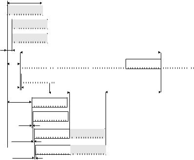
To support reordering and de-multiplexing of the PDUs from different MAC-d flows, the appropriate information is signaled in-band in the form of MAC-es and MAC-e headers. The structures of the MAC-e/es headers are illustrated in Figure 10.26.
Several MAC-d PDUs of the same size and from the same logical channel are concatenated. The Data Description Indicator (DDI) provides information about the logical channel from which the MAC-d PDUs belong, as well as the size of the MAC-d PDUs. The number of MAC-d PDUs is indicated by N. The Transmission Sequence Number (TSN), used to support reordering as described in the previous section, is also attached to the set of MAC-d PDUs.
Enhanced Uplink |
229 |
The MAC-e header consists of a number of DDI and N pairs. A mapping is provided by RRC from the DDI field to a MAC-d PDU size, logical channel ID and MAC-d flow ID. The logical channel also uniquely identifies the reordering queue since reordering in E-DCH is performed per logical channel.
The sequence of DDI and N fields is completed with a predefined value of DDI to indicate the end of the MAC-e header. After the MAC-e header follows a number of MAC-es PDUs, where the number of MAC-es PDUs is the same as the number of DDI and N pairs in the MAC-e header (not counting the predefined DDI value indicating the end of the MAC-e header). After the last MAC-es PDU, the MAC-e PDU may contain padding to fit the current transport block size.
When appropriate, the MAC-e header also includes 18 bits of scheduling information using a special DDI value.
10.3.3Control signaling
To support E-DCH transmissions in the uplink, three downlink channels carrying out-band control signaling are defined:
1.The E-HICH is a dedicated physical channel transmitted from each cell in the active set and used to carry the hybrid ARQ acknowledgments.
2.The E-AGCH is a shared physical channel transmitted from the serving cell only and used to carry the absolute grants.
3.The E-RGCH carries relative grants. From the serving cell, the E-RGCH is a dedicated physical channel, carrying the relative grants. From non-serving cells, the E-RGCH is a common physical channel, carrying the overload indicator.
Thus, a single UE will receive multiple downlink physical control channels. From the serving cell, the UE receives the E-HICH, E-AGCH, and E-RGCH. From each of the non-serving cells, the UE receives the E-HICH and the E-RGCH.
Out-band uplink control signaling is also required to indicate the E-TFC the UE selected, the RSN, and the happy bit. This information is carried on the uplink E-DPCCH.
In addition to the E-DCH-related out-band control signaling, downlink control signaling for transmission of power control bits is required. This is no different from WCDMA in general and is carried on the (F-)DPCH. Similarly, the DPCCH is present in the uplink to provide a phase reference for coherent demodulation as well. The overall E-DCH-related out-band control signaling is illustrated in Figure 10.27.

232 |
3G Evolution: HSPA and LTE for Mobile Broadband |
channelization code. Note that the power for different users’ E-HICH and E-RGCH can be set differently, despite the fact that they share the same code.
When a single NodeB is handling multiple cells and a UE is connected to several of those cells, that is, the UE is in softer handover between these cells, it is reasonable to assume that the NodeB will transmit the same ACK/NAK information to the UE in all these cells. Hence, the UE shall perform soft combining of the E-HICH in this case and the received signal on each of the E-HICH-es being received from the same NodeB shall be coherently added prior to decoding. This is the same approach as used for combining of power control bits already from the first release of WCDMA.
The modulation scheme used for the E-HICH is different for the serving and the non-serving cells. In the serving radio link set, BPSK is used, while for non-serving radio link sets, On–Off Keying (OOK) is used such that NAK is mapped to DTX (no energy transmitted). The reason for having different mappings is to minimize downlink power consumption. Generally, BPSK is preferable if ACK is transmitted for most of the transmissions, while the average power consumption is lower for OOK when NAK is transmitted more than 75% of the time as no energy is transmitted for the NAK. When the UE is not in soft handover, there is only the serving cell in the active set and this cell will detect the presence of an uplink transmission most of the time. Thus, BPSK is preferred for the serving cells. In soft handover, on the other hand, at most one cell is typically able to decode the transmission, implying that most of the cells will transmit a NAK, making OOK attractive. However, note that the NodeB will only transmit an ACK or a NAK in case it detected the presence of an uplink transmission attempts. If not even the presence of a data transmission is detected in the NodeB, nothing will be transmitted as described above. Hence, the E-HICH receiver in the UE must be able to handle the DTX case as well, although from a protocol point of view only the values ACK and NAK exist.
10.3.3.2 E-AGCH
The E-AGCH is a shared channel, carrying absolute scheduling grants consisting of:
•The maximum E-DPDCH/DPCCH power ratio the UE is allowed to use for the E-DCH (5 bits).
•An activation flag (1 bit), used for (de)activating individual hybrid ARQ processes.
•An identity that identifies the UE (or group of UEs) for which the E-AGCH information is intended (16 bits). The identity is not explicitly transmitted but implicitly included in the CRC calculation.

Enhanced Uplink |
|
|
|
|
|
|
|
|
233 |
|||||||||
|
|
|
|
|
|
Identity |
|
|
|
|
|
|
|
|
|
|
|
|
|
|
|
|
|
|
(16 bits) |
|
|
|
|
|
|
|
|
|
|
|
|
1-bit |
|
|
|
|
|
|
|
|
|
|
|
|
|
|
|
|
||
|
|
|
|
|
|
|
|
|
|
|
|
|
|
|
|
|||
|
|
|
|
|
|
|
|
|
|
|
|
|
|
|
|
|||
activation flag |
|
|
Multiplexing |
|
|
ID-specific |
|
|
R 1/3 |
|
|
Puncturing |
|
|
5 times repetition |
|
|
|
5-bit |
|
|
|
|
|
|
|
|
|
|
|
|
||||||
|
|
|
|
CRC attachment |
|
|
convolutional coding |
|
|
|
|
(only for 10 ms TTI) |
|
|
||||
|
|
|
|
|
|
|
|
|
|
|
|
|
|
|||||
power ratio |
|
|
|
|
|
|
|
|
|
|
|
|
||||||
|
|
|
|
|
|
|
|
|
|
|
|
|
|
|
|
|||
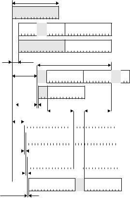
Figure 10.30 E-AGCH coding structure.
Rate 1/3 convolutional coding is used for the E-AGCH and the coded bits are rate matched to 60 bits, corresponding to 2 ms duration at the E-AGCH spreading factor of 256 (Figure 10.30). In case of a 10 ms E-DCH TTI, the 2 ms structure is repeated 5 times. Note that a single channelization code can handle a cell with both TTIs and therefore it is not necessary to reserve two channelization codes in a cell with mixed TTIs. UEs with 2 ms TTI will attempt to decode each subframe of a 10 ms E-AGCH without finding its identity. Similarly, a 10 ms UE will combine five subframes before decoding and the CRC check will fail unless the grant was 10 ms long. For group-wise scheduling, it is unlikely that both 2 and 10 ms UEs will be given the same grant (although the above behavior might be exploited) and the absolute grants for these two groups of UEs can be sent separated in time on the same channelization code.
Each E-DCH-enabled UE receives one E-AGCH (although there may be one or several E-AGCH configured in a cell) from the serving cell. Although the UE is required to monitor the E-AGCH for valid information every TTI, a typical scheduling algorithm may only address a particular UE using the E-AGCH occasionally. The UE can discover whether the information is valid or not by checking the ID-specific CRC.
10.3.3.3E-RGCH
Relative grants are transmitted on the E-RGCH and the transmission structure used for the E-RCGCH is identical to that of the E-HICH. The UE is expected to receive one relative grant per TTI from each of the cells in its active set. Thus, relative grants can be transmitted from both the serving and the non-serving cells.
From the serving cell, the E-RGCH is a dedicated physical channel and the signaled value can be one of +1, DTX, and −1, corresponding to UP, HOLD, and DOWN, respectively. Similar to the E-HICH, the duration of the E-RGCH equals 2 or 8 ms, depending on the E-DCH TTI configured.
From the non-serving cells, the E-RGCH is a common physical channel, in essence a common ‘overload indicator’ used to limit the amount of inter-cell interference. The value on the E-RGCH from the non-serving cells (overload indicator) can only take the values DTX and −1, corresponding to ‘no overload’ and DOWN,
234 |
3G Evolution: HSPA and LTE for Mobile Broadband |
respectively. E-RGCH from the non-serving cells span 10 ms, regardless of the E-DCH TTI configured. Note that Figure 10.28 is representative for the serving cell as each UE is assigned a separate relative grant (from the non-serving cell the E-RGCH is common to multiple UEs).
10.3.3.4 Timing
The timing structure for the E-DCH downlink control channels (E-AGCH, E-RGCH, E-HICH) is designed to fulfill a number of requirements. Additional timing bases in the UE are not desirable from a complexity perspective, and hence the timing relation should either be based on the common pilot or the downlink DPCH as the timing of those channels anyway needs to be handled by the UE.
Common channels, the E-RGCH from the non-serving cell and the E-AGCH, are monitored by multiple UEs and must have a common timing. Therefore, the timing relation of these channels is defined as an offset relative to the common pilot. The duration of the E-AGCH is equal to the E-DCH TTI for which the UE is configured. For the E-RGCH from the non-serving cell, the duration is always 10 ms, regardless of the TTI. This simplifies mixing UEs with different TTIs in a single cell while providing sufficiently rapid inter-cell interference control.
Dedicated channels, the E-RGCH from the serving cell and the E-HICH, are unique for each UE. To maintain a similar processing delay in the UE and NodeB, regardless of the UE timing offset to the common pilot, their timing is defined relative to the downlink DPCH.
The structure of the E-HICH, where multiple E-HICHs share a common channelization code, has influenced the design of the timing relations. To preserve orthogonality between users sharing the same channelization code, the (sub)frame structure of the E-HICHs must be aligned. Therefore, the E-HICH timing is derived from the downlink DPCH timing, adjusted to the closest 2 ms subframe not violating the smallest UE processing requirement.
The number of hybrid ARQ processes directly affects the delay budget in the UE and NodeB. The smaller the number of hybrid ARQ processes, the better from a roundtrip time perspective but also the tighter the implementation requirements. The number of hybrid ARQ processes for E-DCH is fixed to four processes in case of a 10 ms TTI and ten processes in case of a 2 ms TTI. The total delay budget is split between the UE and the NodeB as given by the expressions relating the downlink DPCH timing to the corresponding E-HICH subframe. To allow for 2 ms extra NodeB processing delays, without tightening the UE requirements, the E-HICH duration is 8 ms, rather than 10 ms in case of a 10 ms E-DCH TTI. Note that the acceptable UE and NodeB processing delays vary in a 2 ms interval

Enhanced Uplink |
|
|
|
|
237 |
|||||||||||||
2-bit RSN |
|
|
|
|
|
|
|
|
|
|
|
|
|
E-DPCCH, SF256 |
||||
|
|
|
|
|
(30,10) |
|
|
5 times repetition |
|
|
||||||||
7-bit E-TFCI |
|
|
|
Multiplexing |
|
|
|
|
|
|
|
|
|
|
|
|
||
|
|
|
|
|
|
|
|
|
|
|
||||||||
|
|
|
|
|
TFCI code |
|
|
(only for 10ms TTI) |
|
|
|
|
|
|
|
|
||
1-bit ‘happy’ |
|
|
|
|
|
|
|
|
|
|
|
60 bits, 2 ms |
||||||
|
|
|
|
|
|
|
|
|
|
|
|
|
||||||
|
|
|
|
|
|
|
|
|
|
|
|
|
|
|||||
|
|
|
|
|
|
|
|
|
|
|
|
|
|
|
|
|
|
|
Figure 10.33 E-DPCCH coding.
The complete set of 10 E-DPCCH information bits are encoded into 30 bits using a second-order Reed-Müller code (the same block code as used for coding of control information on the DPCCH). The 30 bits are transmitted over three E-DPCCH slots for the case of 2 ms E-DCH TTI (Figure 10.33). In case of 10 ms E- DCH TTI, the 2 ms structure is repeated 5 times. The E-DPCCH timing is aligned with the DPCCH (and consequently the DPDCH and the E-DPDCH).
To minimize the interference generated in the cell, the E-DPCCH is only transmitted when the E-DPDCH is transmitted. Consequently, the NodeB has to detect whether the E-DPCCH is present or not in a certain subframe (DTX detection) and, if present, decode the E-DPCCH information. Several algorithms are possible for DTX detection, for example, comparing the E-DPCCH energy against a threshold depending on the noise variance.