

755
.pdf270 3G Evolution: HSPA and LTE for Mobile Broadband
Table 12.3 Advanced receiver requirements in the 3GPP UE performance specification [92].
3GPP requirements in TS25.101 |
Dedicated |
HSDPA |
Enhanced |
MBMS |
(basis for requirements) |
channels |
|
uplink |
|
|
|
|
|
|
Type 1 |
DPCH |
HS-DSCH |
E-RGCH |
S-CCPCH |
(Rx diversity) |
F-DPCH |
HS-SCCH |
E-AGCH |
MICH |
|
|
|
E-HICH |
|
Type 2 |
– |
HS-DSCH |
– |
– |
(chip-level equalizer) |
|
|
|
|
Type 3 |
– |
HS-DSCH |
– |
– |
(chip-level equalizer |
|
|
|
|
and Rx diversity) |
|
|
|
|
|
|
|
|
|
12.6.2Receiver diversity (type 1)
Receiver diversity usually means two antennas at the UE, but as explained above the exact implementation is not in any way mandated. A second antenna can be integral or external to the device. Placement of two antennas on or inside a UE can often not be made in an equal fashion, leading to gain imbalance between the antennas paths. Even with such an imbalance, the gain with antenna diversity can still be substantial, especially in an interference limited scenario [54].
There are 3GPP requirements for type 1 receivers defined for HSDPA [92], specifically for demodulation of HS-DSCH and HS-SCCH, both for QPSK and 16QAM modulation. The reason that type 1 requirements were first developed for HSDPA is that the gain is directly visible for HSDPA as an efficient means to reach higher enduser data rates, through use of more codes and higher-order modulation. There is however also gain for other services such as the ones based on the Release 99 dedicated channels. Additional requirements for type 1 receivers are also developed for DCH, MBMS, and Enhanced Uplink (E-RGCH, E-AGCH, and E-HICH).
12.6.3Chip-level equalizers and similar receivers (type 2)
Another way to improve downlink throughput for HSDPA in general and for higher-order modulation specifically is to introduce more advanced receivers in the UE, as described in Chapter 5. In highly dispersive radio environments, the main factor limiting performance is self-interference from multipath propagation, which limits the obtainable carrier-to-interference ratio and reduces the number of occasions for which 16QAM or 64QAM can be used. In time-dispersive scenarios, performance (capacity) losses can be partially compensated for by using advanced receivers that suppress self-interference [112]. The use of rate adaptation provides terminal manufacturers an incentive to implement more advanced receivers since those receivers will result in higher end-user data rates than standard receivers.
HSPA Evolution |
|
|
271 |
|
|
15 |
|
|
RAKE1 |
|
|
|
|
|
|
|
|
|
G-RAKE1 |
|
|
|
|
RAKE2 |
|
|
|
|
G-RAKE2 |
data rate (Mbit/s) |
10 |
|
|
|
|
|
|
|
|
Median |
5 |
|
|
|
|
|
|
|
|
|
0 |
0.5 |
1 |
1.5 |
|
0 |
|||
Mobile-to-base distance (km)
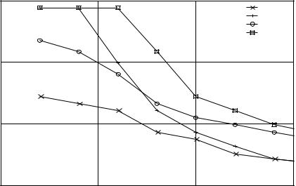
Figure 12.10 Median HSDPA data rate in a mildly dispersive propagation channel for UEs with 15 channelization codes (from [112]). Numbers are with default RAKE receiver (RAKE1), with antenna diversity (RAKE2 = Type 1), G-RAKE (G-RAKE1 = Type 2), and combined G-RAKE and antenna diversity (G-RAKE2 = Type 3).
Multiple strategies for interference-suppressing receivers are possible [29, 113]. The 3GPP type 2 requirements are based on a reference receiver architecture being an LMMSE chip-level equalizer with a 1/2 chip tap spacing and a length of 20 chips (40 taps) [61]. In a UE implementation, any receiver structure can however be used, for example the G-RAKE receiver [29]. There are 3GPP requirements for type 2 receivers defined for HS-DSCH [92].
12.6.4Combination with antenna diversity (type 3)
Combining an advanced receiver such as G-RAKE with receive antenna diversity gives possibilities for further performance gains as shown in Figure 12.10. While antenna diversity gives performance gain over the whole cell for all geometries, the G-RAKE receiver results in additional performance gains when the own-cell interference dominates, that is for higher geometries closer to the base station. With G-RAKE and antenna diversity combined, there is a substantial performance gain for all geometries over the whole cell.
The rationale for introducing combined advanced receivers and antenna diversity in the 3GPP standards has been the need for high performance of high-end UEs supporting ten or more HS-PDSCH channelization codes that need good receiver
272 |
3G Evolution: HSPA and LTE for Mobile Broadband |
performance to efficiently utilize the supported high data rates. It is also driven by the ongoing development of high-end UE platforms that support more and more advanced features, implying that a UE with antenna diversity will often also have advanced receivers and will therefore be a type 1 + 2 UE.
Such requirements have also been introduced in 3GPP as type 3 requirements. The reference receiver for type 3 is a Linear Minimum Mean Square Error (LMMSE) chip-level equalizer with two-branch diversity, but any implementation and receiver structure can be used. There are 3GPP requirements for type 3 receivers in [92] defined for HS-DSCH.
12.6.5Interference cancellation
As was demonstrated in Figure 12.10 for the downlink, antenna diversity provides gain in both high and low geometry cases, while advanced receivers give performance gains mainly in high geometry scenarios when the intra-cell interference dominates. It is identified in 3GPP standardization that further improvements in performance would be useful for lower geometry cases, where other-cell interference dominates. Such improvements could be based on cancellation or rejection of other-cell interference.
Interference cancellation techniques have been studied for a long time [113], where one example is the joint detection scheme developed for UTRA TDD receivers. Another example where substantial gain was shown is the demonstration of parallel interference cancellation in a live WCDMA system, indicating up to 40% multi-cell uplink capacity gain [5]. Implementing interference cancellation for the downlink is however different since the algorithms need to be implemented in each UE that is to benefit from the cancellation. The complexity of the algorithm will then be of higher importance than for an uplink scheme implemented in a base station.
For a UE, the single-branch advanced receivers (type 2) already cancel some of the own-cell interference by accounting for the correlation of the interference in the receiver process. By also accounting for the correlation of other-cell interference, receivers with a G-RAKE or an LMMSE can achieve some suppression of othercell interference.
To achieve higher suppression of other-cell interfering signals, methods such as projection or even explicit demodulation of another base-station signal can be used [113]. The gains of projection-based interference methods have to be weighed against the loss of power and orthogonality that can result from the projection. Explicit demodulation is very complex and may not be suitable for UEs. Both
HSPA Evolution |
273 |
methods rely on a single interfering base station being the dominant interferer, which is the case in approximately 30% of the cell in a multi-cell layout.
With two receive antennas in a UE there are more possibilities to cancel interference as dicussed in Chapter 6. The antenna weights can be selected to strongly mitigate a single interfering other-cell base-station signal. This is also called spatio-temporal equalization.
In the ongoing work in 3GPP, both single-branch and dual antenna interference mitigation techniques will be studied for the UE. Substantial potential gains have been indicated under the certain scenarios and the feasibility of these potential gains on link and system level is to be verified. One topic for study is also how to specify interference mitigation performance for the UE and what metrics to use.
12.7Conclusion
In the previous chapters the evolution of WCDMA has been discussed. HSPA, consisting of improved packet-data support in the downlink and uplink, has been thoroughly described. By adapting the transmission parameters to rapid variations in the radio-channel quality, as well as traffic variations, a significant performance gain in terms of higher peak data rates, reduced latencies, and improved system capacity can be achieved. Technologies such as channel-dependent scheduling, rate adaptation, and hybrid ARQ with soft combining are used to rapidly adjust the transmission parameters.
The broadcast performance of WCDMA has also been considerably improved through the introduction of MBMS. Transmissions from multiple cells are combined in the terminal to obtain diversity, which is of key importance for efficient broadcast performance. Furthermore, the use of application-level coding provides additional diversity as the terminal is able to reconstruct the source data even if some packets are missing.
HSPA is also subject to a continuous evolution and in this chapter, some of these steps have been described. Through the use of MIMO, multiple antennas at both the NodeB and the UE can be use to further increase the peak data rates. The use of Continuous Packet Connectivity provides an ‘always-on’ experience for the end user.
No doubt will this evolution of HSPA continue beyond the steps described in this chapter. However, although these enhancements aims at improving the packetdata experience in a cellular network, it is important to stress that HSPA, MBMS, MIMO, etc. are part of an evolution of WCDMA. These enhancements all build
274 |
3G Evolution: HSPA and LTE for Mobile Broadband |
upon the basic WCDMA structure defined by Release 99. Terminals using a later release of the specifications are able to coexist with terminals from previous releases on the same carrier. Naturally, this sets some constraints on what is possible to introduce, but also offers the significant benefit for an operator to gradually improve the network capacity. In the next chapters, the long-term evolution will be discussed, which puts less emphasis on the backwards compatibility in order to push the performance even further.
278 |
3G Evolution: HSPA and LTE for Mobile Broadband |
The following chapter (Chapter 14), provides an introductory technical overview. This chapter describes the most important technologies used by LTE to support the requirements, including transmission schemes, scheduling, multi-antenna support, and spectrum flexibility. The generic technologies for the schemes were described in Part II while Part IV reveals their specific application to LTE. The chapter can either be read on its own to get a high-level overview of LTE, or as an introduction to the following chapters.
Chapter 15 describes the LTE protocol structure, including RLC, MAC, and the physical layer, explaining the logical and physical channels, and the related procedures and data flows. The LTE physical layer is described in detail in Chapter 16, including details on processing and control signaling for the OFDM downlink transmission and the Single-Carrier FDMA uplink. Finally, Chapter 17 gives the details of the access procedures, including cell search, random access, and paging.
The system architecture is the topic for Chapter 18. In this chapter, details are provided of the HSPA system architecture and the SAE, including the different nodes and interfaces of the radio access network and the core network, their individual functionality, and the functional split between them.
13.1LTE design targets
As discussed in Chapter 2, the 3GPP activity on 3G evolution in the spring of 2005 was setting the objectives, requirements, and targets for LTE. These targets/requirements are documented in 3GPP TR 25.913[86]. The requirements for LTE were divided into seven different areas:
•capabilities,
•system performance,
•deployment-related aspects,
•architecture and migration,
•radio resource management,
•complexity, and
•general aspects.
Below, each of these groups is discussed.
13.1.1Capabilities
The targets for downlink and uplink peak data-rate requirements are 100 Mbit/s and 50 Mbit/s, respectively, when operating in 20 MHz spectrum allocation. For narrower spectrum allocations, the peak data rates are scaled accordingly. Thus, the requirements can be expressed as 5 bit/s/Hz for the downlink and 2.5 bit/s/Hz

LTE and SAE: introduction and design targets |
279 |
for the uplink. As will be discussed below, LTE supports both FDD and TDD operation. Obviously, for the case of TDD, uplink and downlink transmission cannot, by definition, occur simultaneously. Thus the peak data rate requirement cannot be met simultaneously. For FDD, on the other hand, the LTE specifications should allow for simultaneous reception and transmission at the peak data rates specified above.
The latency requirements are split into control-plane requirements and user-plane requirements. The control-plane latency requirements address the delay for transiting from different non-active terminal states to an active state where the mobile terminal can send and/or receive data. There are two measures: one measure is expressed as the transition time from a camped state such as the Release 6 idle1 mode state, where the requirement is 100 ms; The other measure is expressed as the transition time from a dormant state such as Release 6 Cell_PCH2 state where the requirement is 50 ms. For both these requirements, any sleep mode delay and non-RAN signaling are excluded.
The user-plane latency requirement is expressed as the time it takes to transmit a small IP packet from the terminal to the RAN edge node or vice versa measured on the IP layer. The one-way transmission time should not exceed 5 ms in an unloaded network, that is, no other terminals are present in the cell.
As a side requirement to the control-plane latency requirement, LTE should support at least 200 mobile terminals in the active state when operating in 5 MHz. In wider allocations than 5 MHz, at least 400 terminals should be supported. The number of inactive terminals in a cell is not explicitly stated, but should be significantly higher.
13.1.2System performance
The LTE system performance design targets address user throughput, spectrum efficiency, mobility, coverage, and further enhanced MBMS.
In general, the LTE performance requirements in [86] are expressed relative to a baseline system using Release 6 HSPA as described in Part III in this book. For the base station, one transmit and two receive antennas are assumed, while the terminal has a maximum of one transmit and two receive antennas. However, it is
1 Release 6 idle mode is a state where the terminal is unknown to the radio access network, that is, the radio access network does not have any context of the terminal and the terminal does not have any radio resources assigned. The terminal may be in sleep mode, that is, only listening to the network at specific time intervals.
2 Release 6 Cell_PCH state is a state where the terminal is known to the radio access network. Furthermore, the radio access network knows in which cell the terminal is in, but the terminal does not have any radio resources assigned. The terminal may be in sleep mode.
280 |
3G Evolution: HSPA and LTE for Mobile Broadband |
important to point out that the more advanced features described in Chapter 12 as part of the evolution of HSPA are not included in the baseline reference. Hence, albeit the terminal in the baseline system is assumed to have two receive antennas, a simple RAKE receiver is assumed (referred to as Type 1 in Chapter 12). Similarly, spatial multiplexing is not assumed in the baseline system.
The LTE user throughput requirement is specified at two points: at the average and at the fifth percentile of the user distribution (where 95 percent of the users have better performance). A spectrum efficiency target has also been specified, where in this context, spectrum efficiency is defined as the system throughput per cell in bit/s/MHz/cell. These design targets are summarized in Table 13.1.
The mobility requirements focus on the mobile terminals speed. Maximal performance is targeted at low terminal speeds, 0–15 km/h, whereas a slight degradation is allowed for higher speeds. For speeds up to 120 km/h, LTE should provide high performance and for speeds above 120 km/h, the system should be able to maintain the connection across the cellular network. The maximum speed to manage in an LTE system is set to 350 km/h (or even up to 500 km/h depending on frequency band). Special emphasis is put on the voice service that LTE needs to provide with equal quality as supported by WCDMA/HSPA.
The coverage requirements focus on the cell range (radius), that is the maximum distance from the cell site to a mobile terminal in a cell. The requirement for non-interference-limited scenarios is to meet the user throughput, the spectrum efficiency, and the mobility requirements for cells with up to 5 km cell range. For cells with up to 30 km cell range, a slight degradation of the user throughput is tolerated and a more significant degradation of the spectrum efficiency are acceptable relative to the requirements. However, the mobility requirements should be met. Cell ranges up to 100 km should not be precluded by the specifications, but no performance requirements are stated in this case.
Table 13.1 LTE user throughput and spectrum efficiency requirements.
Performance |
Downlink target relative |
Uplink target relative |
measure |
to baseline |
to baseline |
|
|
|
Average user throughput |
3×–4× |
2×–3× |
(per MHz) |
2×–3× |
2×–3× |
Cell-edge user throughput |
||
(per MHz, 5th percentile) |
3×–4× |
2×–3× |
Spectrum efficiency |
||
(bit/s/Hz/cell) |
|
|
|
|
|
LTE and SAE: introduction and design targets |
281 |
The further enhanced MBMS requirements address both broadcast mode and unicast mode. In general, LTE should provide MBMS services better than what is possible with Release 6. The requirement for the broadcast case is a spectral efficiency of 1 bit/s/Hz, corresponding to around 16 mobile-TV channels using in the order of 300 kbit/s each in a 5 MHz spectrum allocation. Furthermore, it should be possible to provide the MBMS service as the only service on a carrier, as well as mixed with other, non-MBMS services. Naturally, simultaneously voice calls and MBMS services should be possible with the LTE specifications.
13.1.3Deployment-related aspects
The deployment-related requirements include deployment scenarios, spectrum flexibility, spectrum deployment, and coexistence and interworking with other 3GPP radio access technologies such as GSM and WCDMA/HSPA.
The requirement on the deployment scenario includes both the case when the LTE system is deployed as a stand-alone system and the case when it is deployed together with WCDMA/HSPA and/or GSM. Thus, this requirement is not in practice limiting the design criteria. The requirements on the spectrum flexibility and deployment are outlined in more detail in the section 13.1.3.1.
The coexistence and interworking with other 3GPP systems and their respective requirements set the requirement on mobility between LTE and GSM, and between LTE and WCDMA/HSPA for mobile terminals supporting those technologies. Table 13.2 lists the interruption requirements, that is, longest acceptable interruption in the radio link when moving between the different radio access technologies, for both real-time and non-real-time services. It is worth noting that these requirements are very loose for the handover interruption time and significantly better values are expected in real deployments.
The coexistence and interworking requirement also address the switching of multicast traffic from being provided in a broadcast manner in LTE to being provided in unicast manner in either GSM or WCDMA, albeit no numbers are given.
Table 13.2 Interruption time requirements, LTE – GSM and LTE –
WCDMA.
|
Non-real-time (ms) |
Real-time (ms) |
|
|
|
LTE to WCDMA |
500 |
300 |
LTE to GSM |
500 |
300 |
|
|
|