

755
.pdf198 |
3G Evolution: HSPA and LTE for Mobile Broadband |
information about the available transmission power in the UE: if the UE is close to its maximum transmission power there is no use in scheduling a (significantly) higher data rate. Hence, there is a need to specify signaling to convey buffer status and power availability information from the UE to the NodeB.
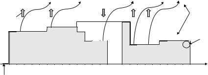
The basis for the scheduling framework is scheduling grants sent by the NodeB to the UE and limiting the E-DCH data rate and scheduling requests sent from the UE to the NodeB to request permission to transmit (at a higher rate than currently allowed). Scheduling decisions are taken by the serving cell, which has the main responsibility for scheduling as illustrated in Figure 10.6 (in case of simultaneous HSDPA and Enhanced Uplink, the same cell is the serving cell for both). However, when in soft handover, the non-serving cells have a possibility to influence the UE behavior to control the inter-cell interference.
Providing the scheduler with the necessary information about the UE situation, taking the scheduling decision based on this information, and communicating the decision back to the UE takes a non-zero amount of time. The situation at the UE in terms of buffer status and power availability may therefore be different at the time of transmission compared to the time of providing the information to the NodeB UE buffer situation. For example, the UE may have less data to transmit than assumed by the scheduler, high-priority data may have entered the transmission buffer or the channel conditions may have worsened such that the UE has less power available for data transmission. To handle such situations and to exploit any interference reductions due to a lower data rate, the scheduling grant does not set the E-DCH data rate, but rather an upper limit of the resource usage. The UE
Non-serving cell |
Serving cell |
Overload ind icator
Requestgrant
Relative
grant Absolute
Absolute Relative
grant grants
Rate |
Request |
Figure 10.6 Overview of the scheduling operation.

Enhanced Uplink |
199 |
select the data rate or, more precisely, the E-DCH Transport Format Combination (E-TFC) within the restrictions set by the scheduler.
The serving grant is an internal variable in each UE, used to track the maximum amount of resource the UE is allowed to use. It is expressed as a maximum E-DPDCH-to-DPCCH power ratio and the UE is allowed to transmit from any MAC-d flow and using any transport block size as long as it does not exceed the serving grant. Hence, the scheduler is responsible for scheduling between UEs, while the UEs themselves are responsible to schedule between MAC-d flows according to rules in the specifications. Basically, a high-priority flow should be served before a low-priority flow.
Expressing the serving grant as a maximum power ratio is motivated by the fact that the fundamental quantity the scheduler is trying to control is uplink interference, which is directly proportional to transmission power. The E-DPDCH transmission power is defined relative to the DPCCH to ensure the E-DPDCH is affected by the power control commands. As the E-DPDCH transmission power typically is significantly larger than the DPCCH transmission power, the E-DPDCH-to- DPCCH power ratio is roughly proportional to the total transmission power,
(PE-DPDCH + PDPCCH)/PDPCCH ≈ PE-DPDCH/PDPCCH, and thus setting a limit on
the maximum E-DPCCH-to-DPCCH power ration corresponds to control of the maximum transmission power of the UE.
The NodeB can update the serving grant in the UE by sending an absolute grant or a relative grant to the UE (Figure 10.7). Absolute grants are transmitted on the shared E-AGCH and are used for absolute changes of the serving grant. Typically, these changes are relatively large, for example to assign the UE a high data rate for an upcoming packet transmission.
Absolute grant |
Relative grant |
Signaled from NodeB |
Internal variable maintained in the UE
Serving grant
E-DPDCH-to-DPCCH power ratio
E-TFC selection |
Determines uplink data rate |
|
|
|
|
|
|
|
Uplink data rate
Figure 10.7 The relation between absolute grant, relative grant and serving grant.
200 |
3G Evolution: HSPA and LTE for Mobile Broadband |
0 10 10 10 10 10 11 11 11 11 12 12 12 12 12 12 12 7 7 7 7 8 8 8 8
|
|
|
|
|
|
|
|
|
|
|
|
|
|
|
|
|
|
|
|
|
|
|
Serving grant |
|
|
|
|
|
|
|
|
|
|
|
|
|
|
|
|
|
|
|
|
|
|
|
(maximum allowed |
|
|
|
|
|
|
|
|
|
|
|
|
|
|
|
|
|
|
|
|
|
|
|
E-DPDCH/DPCCH |
Relative |
|
|
|
|
|
|
|
|
|
|
|
|
|
|
|
|
|
|
|
|
|
|
power ratio) |
|
|
|
|
|
|
|
|
|
|
|
|
|
|
|
|
|
|
|
|
|
|
|
|
grant |
|
|
|
|
|
|
|
|
|
|
|
|
|
|
12 |
|
|
|
|
|
|
|
Actual (used) |
|
|
|
|
|
11 |
|
|
|
|
|
|
|
|
|
|
|
|
|
|
|
|
|
E-DPDCH/DPCCH |
10 10 10 10 10 |
|
|
|
|
10 |
|
|
|
|
|
|
|
|
|
|
|
|
|
power ratio |
||||
|
|
|
|
|
|
|
|
|
|
8 |
8 |
8 |
|
|
|
7 |
7 |
7 |
7 |
8 |
8 |
8 |
8 |
|
|
|
|
|
|
|
|
|
|
|
|
|
0 |
0 |
|
|
|
|
|
||||
|
|
|
|
|
|
|
|
|
|
|
|
|
|
|
|
|
|
|
|
|
|
||
#1 |
#2 |
#3 |
#4 |
#1 |
#2 |
#3 |
#4 |
#1 |
#2 |
#3 |
#4 |
#1 |
#2 |
#3 |
#4 |
#1 |
#2 |
#3 |
#4 |
#1 |
#2 |
#3 |
#4 |
|
|
|
|
|
|
|
|
|
|
|
|
|
|
|
|
|
|
|
|
|
|
|
Time |
Absolute grant received
Figure 10.8 Illustration of relative grant usage.
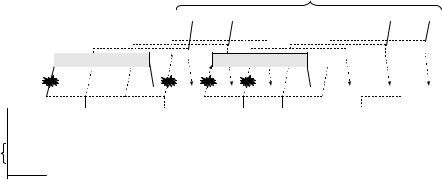
Relative grants are transmitted on the E-RGCH and are used for relative changes of the serving grant. Unlike the absolute grants, these changes are small; the change in transmission power due to a relative grant is typically in the order of 1 dB. Relative grants can be sent from both serving and, in case of the UE being in soft handover, also from the non-serving cells. However, there is a significant difference between the two and the two cases deserve to be treated separately.
Relative grants from the serving cell are dedicated for a single UE, that is each UE receives its own relative grant to allow for individual adjustments of the serving grants in different UEs. The relative grant is typically used for small, possibly frequent, updates of the data rate during an ongoing packet transmission. A relative grant from the serving cell can take one of the three values: ‘UP’, ‘HOLD’, or ‘DOWN.’ The ‘up’ (‘down’) command instructs the UE to increase (decrease) the serving grant, that is to increase (decrease) the maximum allowed E-DPDCH-to- DPCCH power ratio compared to the last used power ratio, where the last used power ratio refers to the previous TTI in the same hybrid ARQ process. The ‘hold’ command instructs the UE not to change the serving grant. An illustration of the operation is found in Figure 10.8.
Relative grants from non-serving cells are used to control inter-cell interference. The scheduler in the serving cell has no knowledge about the interference to neighboring cells due to the scheduling decisions taken. For example, the load in the serving cell may be low and from that perspective, it may be perfectly fine to schedule a high-rate transmission. However, the neighboring cell may not be able to cope with the additional interference caused by the high-rate transmission. Hence, there must be a possibility for the non-serving cell to influence the data rates used. In essence, this can be seen as an ‘emergency break’ or an ‘overload indicator,’ commanding non-served UEs to lower their data rate.
Although the name ‘relative grant’ is used also for the overload indicator, the operation is quite different from the relative grant from the serving cell. First, the
Enhanced Uplink |
201 |
overload indicator is a common signal received by all UEs. Since the non-serving cell only is concerned about the total interference level from the neighboring cell, and not which UE that is causing the interference, a common signal is sufficient. Furthermore, as the non-serving cell is not aware of the traffic priorities, etc., of the UEs it is not serving, there would be no use in having dedicated signaling from the non-serving cell.
Second, the overload indicator only takes two, not three, values – ‘DTX’ and ‘down,’ where the former does not affect the UE operation. All UEs receiving ‘down’ from any of the non-serving cells decrease their respective serving grant relative to the previous TTI in the same hybrid ARQ process.
10.2.2.2Scheduling information
For efficient scheduling, the scheduler obviously needs information about the UE situation, both in terms of buffer status and in terms of the available transmission power. Naturally, the more detailed the information is, the better the possibilities for the scheduler to take accurate and efficient decisions. However, at the same time, the amount of information sent in the uplink should be kept low not to consume excessive uplink capacity. These requirements are, to some extent, contradicting and are in Enhanced Uplink addressed by providing two mechanism complementing each other: the out-band ‘happy bit’ transmitted on the E-DPCCH and in-band scheduling information transmitted on the E-DCH.
Out-band signaling is done through a single bit on the E-DPCCH, the ‘happy bit.’ Whenever the UE has available power for the E-DCH to transmit at a higher data rate compared to what is allowed by the serving grant, and the number of bits in the buffer would require more than a certain number of TTIs, the UE shall set the bit to ‘not happy’ to indicate that it would benefit from a higher serving grant. Otherwise, the UE shall declare ‘happy.’ Note that the happy bit is only transmitted in conjunction with an ongoing data transmission as the E-DPCCH is only transmitted together with the E-DPDCH.
In-band scheduling information provides detailed information about the buffer occupancy, including priority information, and the transmission power available for the E-DCH. The in-band information is transmitted in the same way as user data, either alone or as part of a user data transmission. Consequently, this information benefits from hybrid ARQ with soft combining. As in-band scheduling information is the only mechanism for the unscheduled UE to request resources, the scheduling information can be sent non-scheduled and can therefore be transmitted regardless of the serving grant. Non-scheduled transmissions are not restricted to scheduling information only; the network can configure non-scheduled transmissions also for other data.

202 |
3G Evolution: HSPA and LTE for Mobile Broadband |
10.2.3E-TFC selection
The E-TFC selection is responsible for selecting the transport format of the E-DCH, thereby determining the data rate to be used for uplink transmission, and to control MAC-e multiplexing. Clearly, the selection needs to take the scheduling decisions taken by the NodeB into account, which is done through the serving grant as previously discussed. MAC-e multiplexing, on the other hand, is handled autonomously by the UE. Hence, while the scheduler handles resource allocation between UEs, the E-TFC selection controls resource allocation between flows within the UE. The rules for multiplexing of the flows are given by the specification; in principle, high-priority data shall be transmitted before any data of lower priority.
Introduction of the E-DCH needs to take coexistence with DCHs into account. If this is not done, services mapped onto DCHs could be affected. This would be a non-desirable situation as it may require reconfiguration of parameters set for DCH transmission. Therefore, a basic requirement is to serve DCH traffic first and only spend otherwise unused power resources on the E-DCH. Comparisons can be made with HSDPA, where any dedicated channels are served first and the HS-DSCH may use the otherwise unused transmission power. Therefore, TFC selection is performed in two steps. First, the normal DCH TFC selection is performed as in previous releases. The UE then estimates the remaining power and a second TFC selection step is performed where E-DCH can use the remaining power. The overall E-TFC selection procedure is illustrated in Figure 10.9.
Each E-TFC has an associated E-DPDCH-to-DPCCH power offset. Clearly, the higher the data rate, the higher the power offset. When the required transmitter power for different E-TFCs has been calculated, the UE can calculate the possible E-TFCs to use from a power perspective. The UE then selects the E-TFC by
|
|
|
Absolute |
Relative |
|
|
|
|
|||
|
|
|
grant |
grant |
Power |
|
|||||
|
|
|
|
|
|
|
|
|
|
|
|
|
|
|
|
|
|
|
|
|
|
|
|
|
|
|
|
|
|
|
|
|
|
|
|
|
E-TFC 6 |
|
Serving grant |
|
TFC selection |
|
TFC for |
||||
|
(TB size, b-value) |
|
|
|
|||||||
Available data |
|
|
|
DCHs |
|||||||
E-TFC 5 |
|
|
|
|
|
|
|
|
|
||
|
|
|
|
|
|
|
|
|
|
||
|
(TB size, b-value) |
|
|
|
|
|
|
|
Residual |
|
|
|
E-TFC 4 |
|
|
|
|
|
|
|
|
||
|
|
|
|
|
|
|
|
power |
|
||
|
(TB size, b-value) |
|
|
|
|
|
|
|
|
|
|
|
|
|
|
|
|
|
|
|
|
|
|
Serving grant |
E-TFC 3 |
|
|
|
|
|
|
|
|
|
E-TFC for |
|
|
|
|
|
|
|
|
|
|||
(TB size, b-value) |
|
|
|
E-TFC selection |
|
||||||
|
|
|
|
|
|||||||
|
E-TFC 2 |
|
|
|
|
|
|
|
|
|
E-DCH |
|
|
|
|
|
|
|
|
|
|
|
|
|
(TB size, b-value) |
|
|
|
|
|
|
|
|
|
|
Available power |
E-TFC 1 |
|
|
|
|
|
|
|
|
|
|
(TB size, b-value) |
|
|
|
|
|
|
|
|
|
|
|
|
|
|
|
|
|
|
|
|
|
|
|
Selected |
E-TFC 0 |
|
|
|
|
|
|
|
|
|
|
(TB size, b-value) |
|
|
|
|
|
|
|
|
|
|
|
E-TFC |
|
|
|
|
|
|
|
|
|
|
|
|
|
|
|
|
|
|
|
|
|
|
|
Figure 10.9 Illustration of the E-TFC selection process.
Enhanced Uplink |
203 |
maximizing the amount of data that can be transmitted given the power constraint and the scheduling grant.
The possible transport block sizes being part of the E-TFCs are predefined in the specifications, similar to HS-DSCH. This reduces the amount of signaling, for example at handover between cells, as there is no need to configure a new set of E-TFCs at each cell change. Generally, conformance tests to ensure the UE obeys the specifications are also simpler the smaller the amount of configurability in the terminal.
To allow for some flexibility in the transport block sizes, there are four tables of E-TFCs specified; for each of the two TTIs specified there is one table optimized for common RLC PDU sizes and one general table with constant maximum relative overhead. Which one of the predefined tables that the UE shall use is determined by the TTI and RRC signaling.
10.2.4Hybrid ARQ with soft combining
Hybrid ARQ with soft combining for Enhanced Uplink serves a similar purpose as the hybrid ARQ mechanism for HSDPA – to provide robustness against transmission errors. However, hybrid ARQ with soft combining is not only a tool for providing robustness against occasional errors; it can also be used for enhanced capacity as discussed in the introduction. As hybrid ARQ retransmissions are fast, many services allow for a retransmission or two. Combined with incremental redundancy, this forms an implicit rate control mechanism. Thus, hybrid ARQ with soft combining can be used in several (related) ways:
•To provide robustness against variations in the received signal quality.
•To increase the link efficiency by targeting multiple transmission attempts, for example by imposing a maximum number of transmission attempts and operating the outer loop power control on the residual error event after soft combining.
To a large extent, the requirements on hybrid ARQ are similar to HSDPA and, consequently, the hybrid ARQ design for Enhanced Uplink is fairly similar to the design used for HSDPA, although there are some differences as well, mainly originating from the support of soft handover in the uplink.
Similar to HSDPA, Enhanced Uplink hybrid ARQ spans both the MAC layer and the physical layer. The use of multiple parallel stop-and-wait processes for the hybrid ARQ protocol has proven efficient for HSDPA and is used for Enhanced Uplink for the same reasons – fast retransmission and high throughput
204 |
3G Evolution: HSPA and LTE for Mobile Broadband |
combined with low overhead of the ACK/NAK signaling. Upon reception of the single transport block transmitted in a certain TTI and intended for a certain hybrid ARQ process, the NodeB attempts to decode the set of bits and the outcome of the decoding attempt, ACK or NAK, is signaled to the UE. To minimize the cost of the ACK/NAK, a single bit is used. Clearly, the UE must know which hybrid ARQ process a received ACK/NAK bit is associated with. Again, this is solved using the same approach as in HSDPA, that is the timing of the ACK/NAK is used to associate the ACK/NAK with a certain hybrid ARQ process. A well-defined time after reception of the uplink transport block on the E-DCH, the NodeB generates an ACK/NAK. Upon reception of a NAK, the UE performs a retransmission and the NodeB performs soft combining using incremental redundancy.
The handling of retransmissions, more specifically when to perform a retransmission, is one of the major differences between the hybrid ARQ operation in the uplink and the downlink (Figure 10.10). For HSDPA, retransmissions are scheduled as any other data and the NodeB is free to schedule the retransmission to the UE at any time instant and using a redundancy version of its choice. It may also address the hybrid ARQ processes in any order, that is it may decide to perform retransmissions for one hybrid ARQ process, but not for another process in the same UE. This type of operation is often referred to as adaptive asynchronous hybrid ARQ. Adaptive since the NodeB may change the transmission format and asynchronous since retransmissions may occur at any time after receiving the ACK/NAK.
For the uplink, on the other hand, a synchronous, non-adaptive hybrid ARQ operation is used. Hence, thanks to the synchronous operation, retransmissions occur a predefined time after the initial transmission, that is they are not explicitly scheduled. Likewise, the non-adaptive operation implies the transport format and redundancy version to be used for each of the retransmissions is also known from the time of the original transmission. Therefore, neither is there a need to explicitly scheduling the retransmissions nor is there a need for signaling the redundancy version the UE shall use. This is the main benefit of synchronous operation of the hybrid ARQ – minimizing the control signaling overhead. Naturally, the possibility to adapt the transmission format of the retransmissions to any changes in the channel conditions are lost, but as the uplink scheduler in the NodeB has less knowledge of the transmitter status – this information is located in the UE and provided to the NodeB using in-band signaling not available until the hybrid ARQ has successfully decoded the received data – than the downlink scheduler, this loss is by far outweighed by the gain in reduced control signaling overhead.
Apart from the synchronous vs. asynchronous operation of the hybrid ARQ protocol, the other main difference between uplink and downlink hybrid ARQ is the use

Enhanced Uplink |
205 |
Time between transmission and retransmission fixed and known to both UE and NodeB  no need to signal hybrid ARQ process number
|
|
3 |
|
0 |
1 |
2 |
|
3 |
0 |
1 |
2 |
3 |
|
|
Hybrid ARQ process number |
Synchronous hybrid ARQ |
|
|
|
|
|
||||||||
|
|
|
Retransmissions may occur at any time |
|
|
|
|
|
|
|
||||
|
|
|
|
need to explicitly signal hybrid ARQ process number |
|
|
|
|
|
|||||
|
|
|
|
|
|
|
|
|
|
|
|
|
|
|
|
3 |
|
0 |
1 |
2 |
|
3 |
? |
? |
? |
? |
|
|
|
Asynchronous hybrid ARQ
Figure 10.10 Synchronous vs. asynchronous hybrid ARQ.
of soft handover in the former case. In soft handover between different NodeBs, the hybrid ARQ protocol is terminated in multiple nodes, namely all the involved NodeBs. For HSDPA, on the other hand, there is only a single termination point for the hybrid ARQ protocol – the UE. In Enhanced Uplink, the UE therefore needs to receive ACK/NAK from all involved NodeBs. As it, from the UE perspective, is sufficient if at least one of the involved NodeBs receive the transmitted transport block correctly, it considers the data to be successfully delivered to the network if at least one of the NodeBs signals an ACK. This rule is sometimes called ‘or-of-the-ACKs.’ A retransmission occurs only if all involved NodeBs signal a NAK, indicating that none of them has been able to decode the transmitted data.
As known from the HSDPA description, the use of multiple parallel hybrid ARQ processes cannot itself provide in-sequence delivery and a reordering mechanism is required (Figure 10.11). For HSDPA, reordering is obviously located in the UE. The same aspect with out-of-sequence delivery is valid also for the uplink, which calls for a reordering mechanism also in this case. However, due to the support of soft handover, reordering cannot be located in the NodeB. Data transmitted in one hybrid ARQ process may be successfully decoded in one NodeB, while data transmitted in the next hybrid ARQ process may happen to be correctly decoded in another NodeB. Furthermore, in some situations, several involved NodeBs may succeed in decoding the same transport block. For these reasons, the reordering mechanism needs to have access to the transport blocks delivered from all involved NodeBs and therefore the reordering is located in the RNC. Reordering also removes any duplicates of transport blocks detected in multiple NodeBs.
The presence of soft handover in the uplink has also impacted the design of the control signaling. Similar to HSDPA, there is a need to indicate to the receiving
206 |
|
|
|
|
|
|
|
|
3G Evolution: HSPA and LTE for Mobile Broadband |
||||||||||||||||
|
|
|
|
|
|
|
|
|
|
|
|
|
|
To reordering mechanism in RNC |
|
|
|
|
|||||||
|
|
|
|
|
|
|
|
|
TrBlk 1 |
TrBlk 2 |
|
|
|
|
|
|
|
|
TrBlk 5 |
TrBlk 3 |
|||||
|
|
|
|
|
|
|
|
|
|
|
|
|
|
|
|
|
|
|
|
|
|
|
|
||
|
|
|
|
|
|
|
|
|
|
|
|
|
processing |
|
|
|
|
|
|
|
|
|
|
||
|
|
|
|
|
|
|
|
|
|
Receiver |
|
|
|
|
|
Receiver processing |
|
|
|
||||||
|
|
|
|
|
|
Receiver |
processing |
|
|
|
|
Receiver |
processing |
|
|
|
|||||||||
Node B |
|
|
|
Receiver |
processing |
|
|
|
|
|
Receiver |
processing |
|
|
|
|
|
|
|
||||||
|
|
|
|
|
|
|
|
|
|
|
|
|
|
|
|
|
|
|
|
|
|
|
|
|
|
|
|
Receiver |
processing |
|
|
|
Receiver processing |
|
|
|
|
|
|
|
|
||||||||||
|
|
|
|
|
|
|
|
|
|
|
|
|
|
|
|
|
|
|
|
||||||
|
|
|
|
|
|
|
|
|
|
|
|
|
|
|
|
|
|
||||||||
|
|
|
|
|
NAK |
ACK |
ACK |
NAK |
NAK |
|
NAK |
ACK |
ACK |
||||||||||||
|
|
|
|
|
|
|
|
|
|
|
|
|
|
|
|
|
|
|
|
|
|
|
|
|
|
UE |
TrBlk 0 |
1 |
2 |
3 |
|
|
|
0 |
|
|
4 |
|
5 |
|
3 |
|
0 |
|
|
4 |
|
|
|
||
|
|
|
|
|
|
||||||||||||||||||||
|
|
|
|
|
|
|
|
|
|
|
|
|
|
|
|
|
|
|
|
|
|
|
|
|
|
Signaled |
RSN 0 |
RSN 0 |
RSN 0 |
RSN |
0 |
RSN 1 |
RSN 0 |
RSN 0 |
RSN 1 |
RSN 2 |
RSN 0 |
|
|
|
|||||||||||
|
|
|
|
|
|
|
|
|
|
|
|
|
|
|
|
|
|
|
|
|
|
|
|
|
|
|
|
|
|
|
|
|
|
|
|
|
|
|
|
|
|
|
|
|
|
|
|
|
|
|
|
Derived |
Proc 0 |
Proc 1 |
Proc 2 |
Proc 3 |
Proc 0 |
Proc 1 |
Proc 2 |
Proc 3 |
Proc 0 |
Proc 1 |
|
|
|
||||||||||||
RV 0 |
RV 0 |
RV 0 |
RV 0 |
RV 1 |
RV 0 |
RV 0 |
RV 1 |
RV 2 |
RV 0 |
|
|
|
|||||||||||||
|
|
|
|
||||||||||||||||||||||
|
10 ms TTI |
|
Fixed timing relation |
|
|
|
|
|
|
|
|
|
|
|
|
|
|
|
|
|
|
|
|||
|
|
|
|
|
|
|
|
|
|
|
|
|
|
|
|
|
|
|
|
|
|
|
|
|
|
Figure 10.11 Multiple hybrid ARQ processes for Enhanced Uplink.
end whether the soft buffer should be cleared, that is the transmission is an initial transmission, or if soft combining with the soft information stored from previous transmissions in this hybrid ARQ process should take place. HSDPA relies on a single-bit new-data indicator, for this purpose. If the NodeB misinterpreted an uplink NAK as an ACK and continues with the next packet, the UE can capture this error event by observing the single-bit ‘new-data indicator’ which is incremented for each new packet transmission. If the new-data indicator is incremented, the UE will clear the soft buffer, despite its contents were not successfully decoded, and try to decode the new transmission. Although a transport block is lost and has to be retransmitted by the RLC protocol, the UE does not attempt to soft combine coded bits originating from different transport blocks and therefore the soft buffer is not corrupted. Only if the uplink NAK and the downlink new-data indicator are both misinterpreted, which is a rare event, will the soft buffer be corrupted.
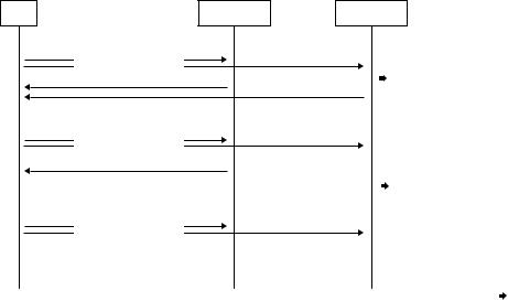
For Enhanced Uplink, a single-bit new-data indicator would work in absence of soft handover. Only if the downlink NAK and the uplink control signaling both are misinterpreted will the NodeB soft buffer be corrupted. However, in presence of soft handover, this simple method is not sufficient. Instead, a 2-bit Retransmission Sequence Number (RSN) is used for Enhanced Uplink. The initial transmission sets RSN to zero and for each subsequent transmission the RSN is incremented by one. Even if the RSN only can take values in the range of 0 to 3, any number of retransmissions is possible; the RSN simply remains at 3 for the third and later retransmissions. Together with the synchronous protocol operation, the NodeB knows when a retransmission is supposed to occur and with what RSN. The simple example in Figure 10.12 illustrates the operation. As the first NodeB acknowledged packet A, the UE continues with packet B, despite that the second NodeB did not correctly decode the packet. At the point of transmission of packet B, the second NodeB expects a retransmission of packet A, but due to the uplink channel conditions at this point in time, the second NodeB does not even detect the presence
Enhanced Uplink |
|
207 |
UE |
NodeB 1 |
NodeB 2 |
Packet A, RSN 0 |
|
Transmission received, |
|
decoding failed |
|
ACK |
|
NAK, store soft bits |
|
|
for packet A |
NAK |
|
|
Packet B, RSN 0 |
|
Expects retransmission |
|
of packet A with RSN 1 |
|
ACK |
|
but did not receive the |
|
transmission |
|
|
|
|
|
|
no ACK/NAK feedback |
Packet C, RSN 0 |
|
Two possible cases |
|
• retransmission of packet |
|
|
|
|
|
|
A with RSN 2 or |
|
|
• transmission of new packet |
|
|
with RSN 0 |
|
|
Since the received RSN 0, |
|
|
the ambiguity is resolved |
|
|
soft buffer corruption avoided |
Figure 10.12 Retransmissions in soft handover.
of a transmission. Again, the first NodeB acknowledge the transmission and the UE continues with packet C. This time, the second NodeB does receive the transmissions and, thanks to the synchronous hybrid ARQ operation, can immediately conclude that it must be a transmission of a new packet. If it were a retransmission of packet A, the RSN would have been equal to two. This example illustrated the improved robustness from a 2-bit RSN together with a synchronous hybrid ARQ operation. A scheme with a single-bit ‘new-data indicator,’ which can be seen as a 1-bit RSN, would not have been able to handle the fairly common case of a missed transmission in the second NodeB. The new-data indicator would in this case be equal to zero, both in the case of a retransmission of packet A and in case the of an initial transmission of packet C, thereby leading to soft buffer corruption.
Soft combining in the hybrid ARQ mechanism for Enhanced Uplink is based on incremental redundancy. Generation of redundancy versions is done in a similar way as for HSDPA by using different puncturing patterns for the different redundancy versions. The redundancy version is controlled by the RSN according to a rule in the specifications, see further Section 10.3.2.
For Turbo codes, the systematic bits are of higher importance than the parity bits as discussed in Chapter 7. Therefore, the systematic bits should be included in the initial transmission to allow for decodability already after the first transmission attempts. Furthermore, for the best gain with incremental redundancy, the retransmissions should contain additional parity. This leads to a design where the