

755
.pdf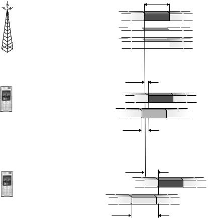


LTE physical layer |
355 |
close to the base station and experiences a small propagation delay, TP,1. Thus, for this mobile terminal, a small value of the timing advance offset TA,1 is sufficient to compensate for the propagation delay and to ensure the correct timing at the base station. On the other, a larger value of the timing advance is required for second mobile terminal (MT-2), which is located at a larger distance from the base station and thus experiencing a larger propagation delay.
The timing-advance value for each mobile terminal is determined by the network based on measurements on the respective uplink transmissions. Hence, as long as a mobile terminal carries out uplink data transmission, this can be used by the receiving base station to estimate the uplink receive timing and thus be a source for the timing-advance commands. Note that any uplink transmission can be used for the timing estimation. The network can, for example, exploit regular transmissions of channel-quality reports in the uplink for timing estimation in absence of data transmission from a specific mobile terminal. In this way, the mobile terminal can immediately restart uplink-orthogonal data transmission without the need for a timing re-alignment phase.
Based on the uplink measurements, the network determines the required timing correction for each terminal. If the timing of a specific terminal needs correction, the network issues a timing-advance command for this specific mobile terminal, instructing it to retard or advance its timing relative to the current uplink timing. Typically, timing-advance commands to a mobile terminal are transmitted relatively infrequent, e.g. one or a few times per second.
If the mobile terminal does not transmit anything in the uplink for a longer period, no uplink transmission should be carried out. In that case, uplink time alignment may be lost and restart of data transmission must then be preceded by an explicit timing-re-alignment phase using random access, as described in the next chapter, to restore the uplink time alignment.
LTE access procedures |
359 |
synchronization signal is transmitted. Basically, if (s1, s2) is an allowable pair of sequences, where s1 and s2 represent the secondary synchronization signal in subframe zero and five, respectively, the reverse pair (s2, s1) is not a valid sequence pair. By exploiting this property, the terminal can resolve the 5 ms timing ambiguity resulting from the first step in the cell-search procedure and determine the frame timing. Furthermore, as each combination (s1, s2) represents one of the cellidentity groups, also the cell identity group is obtained from the second cell-search step. From the cell identity group, the terminal also obtains knowledge about which pseudo-random sequence is used for generating the reference signal in the cell.
Once the cell-search procedure is complete, the terminal receive the broadcasted system information to obtain the remaining parameters, for example, the transmission bandwidth used in the cell.
17.1.2 Time/frequency structure of synchronization signals
The general time-frequency structure has already been briefly described above and is illustrated in Figure 17.1. As seen in the figure, the primary and secondary synchronization signals are transmitted in two subsequent OFDM symbols. This structure has been chosen to allow for coherent processing of the secondary synchronization signal at the terminal. After the first step, the primary synchronization signal is known and can thus be used for channel estimation. This channel estimate can subsequently be used for coherent processing of the received signal prior to the second step in order to improve performance. However, the placement of the primary and secondary synchronization signals next to each other also implies that the terminal in the second step needs to blindly estimate the cyclic-prefix length. This, however, is a low-complexity operation.
In many cases, the timing in multiple cells is synchronized such that the frame start in neighboring cells coincides in time. One reason hereof is to enable MBSFN operation. However, the synchronous operation also implies that transmission of the primary synchronization signals in different cells occur at the same time. Channel estimation based on the primary synchronization signal will therefore reflect the composite channel from all cells if the same primary synchronization signal is used in all cells. Obviously, for coherent demodulation of the second synchronization signal, which is different in different cells, an estimate of the channel from the cell of interest is required, not an estimate of the composite channel from all cells. Therefore, LTE supports multiple sequences for the primary synchronization signal. In case of coherent reception in a deployment with time-synchronized cells, neighboring cells can use different primary synchronization sequences to alleviate the channel-estimation problem describe above. Furthermore, as described above, the primary synchronization signal also carries part of the cell identity.
360 |
|
3G Evolution: HSPA and LTE for Mobile Broadband |
|
Synchronization signal, |
0 |
Synchronization signal, |
|
frequency-domain representation |
|
time-domain representation |
|
|
|
|
IFFT |
36 Subcarriers |
36 Subcarriers |
|
|
|
DC |
0 |
|
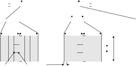
Figure 17.2 Generation of the synchronization signal in the frequency domain.
From a TDD perspective, locating the synchronization signal at the end of the first slot in the subframe, instead of the second slot, is beneficial as it implies fewer restrictions on the creation of guard times between uplink and downlink. Alternatively, if the synchronization signals were located in the last slot of the subframe, there would be no possibility to obtain the guard time required for TDD by removing downlink OFDM symbols as discussed in Chapter 16. Also, note that, for TDD operation, the location of the synchronization signals implies that subframe zero and five always are downlink subframes.
At the beginning of the cell-search procedure, the cell bandwidth is not necessarily known. In principle, detection of the transmission bandwidth could have been made part of the cell-search procedure. However, as this would complicate the overall cell-search procedure, it is preferable to maintain the same cell-search procedure, regardless of the overall cell transmission bandwidth. The terminal can then be informed about the actual bandwidth in the cell from the broadcast channel. Therefore, to maintain the same frequency-domain structure of the synchronization signals, regardless of the cell system bandwidth, the synchronization signals are always transmitted using the 72 center subcarriers, corresponding to a bandwidth in the order of 1 MHz. Figure 17.2 illustrates a possible implementation for generation of the synchronization signals. Thirty-six subcarriers on each side of the DC subcarrier in the frequency domain are reserved for the synchronization signal. By using an IFFT, the corresponding time-domain signal can be generated. The size of the IFFT, as well as the number of subcarriers set to zero in Figure 17.2, depends on the system bandwidth. Subcarriers not used for transmission of synchronization signals can be used for data transmission.
17.1.3Initial and neighbor-cell search
Finding a cell to connect to after power up of the terminal is obviously an important case. However, equally important is the possibility to identify candidate cells for handover as part of the mobility support, when the terminal connection is moved from one cell to another. These two situations are usually referred to as initial cell search and neighbor-cell search, respectively.
362 |
3G Evolution: HSPA and LTE for Mobile Broadband |
||||
|
|
|
|
|
|
|
|
|
|
|
|
UE |
|
eNodeB |
|
AGW |
|
|
|
|
|
|
|
|
|
|
|
|
|
Synchronize to downlink timing (from cell search)
Step 1: Random access preamble
Step 2: Random access response
Adjust uplink timing
Step 3: RRC signaling |
Only if UE is not known in NodeB |
|
(initial random access) |
||
|
||
Step 4: RRC signaling |
|
user data
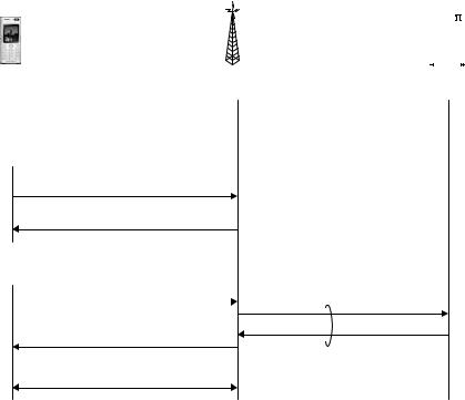
Figure 17.3 Overview of the random access procedure.
synchronization, and establishment of a unique terminal identity, the C-RNTI, known to both the network and the terminal. Thus, random access is used not only for initial access, that is, when moving from LTE_DETACHED or LTE_IDLE to LTE_ACTIVE (see Chapter 15 for a discussion of different terminal states), but also after periods of uplink inactivity when uplink synchronization is lost in LTE_ACTIVE.
The overall random-access procedure, illustrated in Figure 17.3, consists of four steps:
1.The first step consists of transmission of a random-access preamble, allowing the eNodeB to estimate the transmission timing of the terminal. Uplink synchronization is necessary as the terminal otherwise cannot transmit any uplink data.
2.The second step consists of the network transmitting a timing advance command to adjust the terminal transmit timing, based on the timing measurement in the first step. In addition to establishing uplink synchronization, the second step also assigns uplink resources to the terminal to be used in the third step in the random access procedure.
3.The third step consists of transmission of the mobile-terminal identity to the network using the UL-SCH similar to normal scheduled data. The exact content
LTE access procedures |
363 |
of this signaling depends on the state of the terminal, in particular whether it is previously known to the network or not.
4.The fourth and final step consists of transmission of a contention-resolution message from the network to the terminal on the DL-SCH. This step also resolves any contention due to multiple terminals trying to access the system using the same random-access resource.
Only the first step uses physical-layer processing specifically designed for random access. The last three steps all utilizes the same physical-layer processing as used for normal uplink and downlink data transmission. In the following, each of these steps are described in more detail.
17.2.1Step 1: Random access preamble transmission
The first step in the random access procedure is the transmission of a randomaccess preamble. The main purpose of the preamble is to indicate to the network the presence of a random-access attempt and to obtain uplink time synchronization within a fraction of the uplink cyclic prefix.
In general, random-access-preamble transmissions can be either orthogonal or non-orthogonal to user data. In WCDMA, the preamble is non-orthogonal to the uplink data transmission. This provides the benefit of not having to semi-statically allocate any resources for random access. However, to control the random- access-to-data interference, the transmit power of the random-access preamble must be carefully controlled. In WCDMA, this is solved through the use of a power-ramping procedure, where the terminal gradually increases the power of the random-access preamble until it is successfully detected at the base station. Although this is a suitable solution to the interference problem, the ramping procedure introduces a delay in the overall random-access procedure. Therefore, from a delay perspective, a random-access procedure not requiring power ramping is beneficial.
In LTE, the transmission of the random-access preamble can be made orthogonal to uplink user-data transmissions and, as a consequence, no power ramping is necessary (although the specifications allow for ramping). Orthogonality between user data transmitted from other terminals and random-access attempts is obtained in both the time and frequency domains. The network broadcasts information to all terminals in which time-frequency resources random-access preamble transmission is allowed. To avoid interference between data and random-access preambles, the network avoids scheduling any uplink transmissions in those time-frequency resources. This is illustrated in Figure 17.4. Since the fundamental time unit for data transmission in LTE is 1 ms, a subframe is reserved for preamble