

755
.pdf54 |
|
|
|
|
|
|
|
|
|
|
|
|
|
|
|
|
|
3G Evolution: HSPA and LTE for Mobile Broadband |
||||||||||||||||
|
|
|
|
|
|
|
|
|
|
|
|
|
|
|
|
|
|
|
|
|
|
|
|
|
|
|
|
|
|
|
||||
|
|
|
|
|
|
|
|
|
|
|
|
|
|
|
|
|
|
|
|
|
|
|
Receiver |
|
|
|
|
|
|
|
||||
|
|
|
Transmitter |
|
|
|
|
|
|
|
|
|
|
|
Noise |
|
|
|
|
|||||||||||||||
|
a0 |
|
|
|
|
|
|
|
|
|
|
|
|
|
|
|
|
|
|
|
|
|
|
|
|
|
b0 |
|
||||||
|
|
|
|
|
|
|
|
|
|
|
|
|
|
|
|
|
|
|
|
|
|
|
|
|
|
|
||||||||
|
|
|
|
|
|
|
|
|
|
|
|
|
|
|
|
|
|
|
|
|
|
|
|
|
|
|
||||||||
|
|
|
OFDM |
|
|
|
|
|
|
|
|
|
|
|
|
|
|
|
nTs |
|
rn |
|
|
|
|
|
OFDM |
|
|
|||||
|
|
|
|
|
|
|
|
|
|
|
|
|
|
|
|
|
|
|
|
|
|
|
|
|
|
|||||||||
|
|
|
|
|
|
|
|
CP |
|
|
|
Channel |
|
|
|
|
|
|
|
|
CP |
|
|
|
|
|
||||||||
|
|
|
|
|
|
|
|
|
|
|
|
|
|
|
|
|
|
|
|
|||||||||||||||
|
|
|
|
|
mod. |
|
|
|
insertion |
|
|
|
|
h(t) |
|
|
|
|
|
|
|
|
|
|
removal |
|
|
demod. |
|
|
||||
aN |
1 |
|
|
|
(IFFT ) |
|
|
|
|
|
|
|
|
|
|
|
|
|
|
|
|
|
|
|
(FFT ) |
|
|
1 |
||||||
|
|
|
|
|
|
|
|
|
|
|
|
|
|
|
|
|
|
|
|
|
|
|
|
|
|
|
|
|
||||||
|
|
|
|
|
|
|
|
|
|
|
|
|
|
|
|
|
|
|
|
|
|
|
|
|
|
|
|
|
|
|
bN |
|||
|
|
|
|
|
|
|
|
|
|
|
|
|
|
|
|
|
|
|
|
|
|
|
|
|
|
|
|
|
|
|||||
c |
|
|
|
|
|
|
|
|
|
|
H0 |
|
|
|
n0 |
|
|
|
|
|
|
|
|
|
c |
|
||||||||
|
|
|
|
|
|
|
|
|
|
|
|
|
|
|
|
|
|
|
|
|
|
|
|
|
||||||||||
|
|
|
|
|
|
|
a0 |
|
|
|
|
|
|
|
|
|
|
|
|
|
b0 |
|
bi Hi ·ai ni |
|
|
|
|
|||||||
|
|
|
|
|
|
|
|
|
|
|
|
|
|
|
|
|
|
|
|
|
|
|
|
|
||||||||||
|
|
|
|
|
|
|
|
|
|
|
|
|
|
|
|
|
|
|
|
|
|
|
|
|
||||||||||
|
|
|
|
|
|
|
|
|
|
|
|
|
|
|
|
|
|
|
|
|
|
|
|
|
||||||||||
|
|
|
|
|
|
|
|
|
|
|
|
|
|
|
|
|
|
|
|
|
|
|
|
|
|
|
|
|
||||||
|
|
|
|
|
|
|
|
|
|
HN |
1 |
nN |
1 |
|
|
|
|
|
|
Hi : Channel response for symbol ai |
||||||||||||||
|
|
|
|
|
|
|
|
|
|
|
c |
|
|
|
|
c |
|
|
|
|
|
|
|
|
ni : Noise imposed on symbol ai |
|
||||||||
|
|
|
|
|
aN |
|
|
|
|
|
|
|
|
|
|
|
|
|
|
|
bN |
|
|
|||||||||||
|
|
|
|
|
1 |
|
|
|
|
|
|
|
|
|
|
|
|
|
1 |
|
|
|
|
|
|
|
|
|
||||||
|
|
|
|
|
|
|
|
|
|
|
|
|
|
|
|
|
|
|
|
|
|
|
|
|
|
|
||||||||
|
|
|
|
|
|
c |
|
|
|
|
|
|
|
|
|
|
|
|
|
|
|
|
c |
|
|
|
|
|
|
|
|
|
|
|
Figure 4.10 Frequency-domain model of OFDM transmission/reception.
The demodulator output bk in Figure 4.10 is the transmitted modulation symbol ak scaled and phase rotated by the complex frequency-domain channel tap Hk and impaired by noise nk. To properly recover the transmitted symbol for further processing, for example data demodulation and channel decoding, the receiver should multiply bk with the complex conjugate of Hk, as illustrated in Figure 4.11, This is often expressed as a one-tap equalizer being applied to each received subcarrier.
4.6Channel estimation and reference symbols
As described above, to demodulate the transmitted modulation symbol ak and allow for proper decoding of the transmitted information at the receiver side, scaling with the complex conjugate of the frequency-domain channel tap Hk should be applied after OFDM demodulation (FFT processing) (see Figure 4.11). To be able to do this, the receiver obviously needs an estimate of the frequency-domain channel taps H0, . . ., HNc−1.
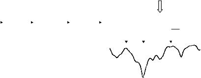
The frequency-domain channel taps can be estimated indirectly by first estimating the channel impulse response and, from that, calculate an estimate of Hk. However, a more straightforward approach is to estimate the frequency-domain channel taps directly. This can be done by inserting known reference symbols, sometimes also referred to as pilot symbols, at regular intervals within the OFDM time-frequency grid, as illustrated in Figure 4.12. Using knowledge about the reference symbols, the receiver can estimate the frequency-domain channel around the location of the reference symbol. The reference symbols should have a sufficiently high density in both the time and the frequency domain to be able to provide estimates for the entire time/frequency grid also in case of radio channels subject to high frequency and/or time selectivity.

OFDM transmission |
|
|
|
|
|
|
|
|
|
55 |
|||||
|
|
Frequency-domain channel |
|
|
|
||||||||||
|
|
|
Receiver |
|
|
||||||||||
|
|
|
|
|
|
|
|
|
|||||||
|
|
|
H0 |
n0 |
|
H0* |
|
||||||||
|
a0 |
|
|
|
|
|
b0 |
|
|
|
|
aˆ0 |
|||
|
|
|
|
|
|
|
|
|
|
||||||
|
|
|
|
|
|
|
|
|
|
|
|
|
|||
|
HNc 1 |
nNc 1 |
|
HN* |
1 |
||||||||||
|
|
|
|
|
|
||||||||||
|
|
|
|
|
|
|
bN |
1 |
|
c |
|
|
|
|
|
|
|
|
|
|
|
|
|
|
|
|
|
|
|
||
|
|
|
|
|
|
|
|
|
|
|
|
|
|
||
aN |
1 |
|
|
|
|
|
c |
|
|
|
|
|
|
aˆ |
|
|
|
|
|
|
|
|
|
|
|
|
|
Nc 1 |
|||
|
|
|
|
|
|
|
|
|
|||||||
c |
|
|
|
|
|
|
|
|
|
|
|
|
|
|
|
Figure 4.11 Frequency-domain model of OFDM transmission/reception with ‘one-tap equalization’ at the receiver.
 Reference symbol
Time
Figure 4.12 Time-frequency grid with known reference symbols.
Different more or less advanced algorithms can be used for the channel estimation, ranging from simple averaging in combination with linear interpolation to Minimum-Mean-Square-Error (MMSE) estimation relying on more detailed knowledge of the channel time/frequency-domain characteristics. Readers are referred to, for example, [31] for a more in-depth discussion on channel estimation for OFDM.
4.7Frequency diversity with OFDM: importance of channel coding
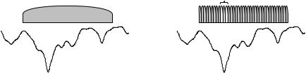
As discussed in Section 3.3 in the previous chapter, a radio channel is always subject to some degree of frequency selectivity, implying that the channel quality will vary in the frequency domain. In case of a single wideband carrier, such as a WCDMA carrier, each modulation symbol is transmitted over the entire signal bandwidth. Thus, in case of the transmission of a single wideband carrier over a highly frequency-selective channel (see Figure 4.13a), each modulation symbol will be transmitted both over frequency bands with relatively good quality (relatively high signal strength) and frequency bands with low quality (low signal strength). Such transmission of information over multiple frequency bands with different instantaneous channel quality is also referred to as frequency diversity.
56 |
3G Evolution: HSPA and LTE for Mobile Broadband |
Single wideband carrier |
OFDM signal |
|
Subcarrier experiencing |
|
very bad channel quality |
(a) |
(b) |
Figure 4.13 Transmission of single wideband |
carrier and OFDM transmission over a |
frequency-selective channel. |
|
On the other hand, in case of OFDM transmission each modulation symbol is mainly confined to a relatively narrow bandwidth. Thus, in case of OFDM transmission over a frequency-selective channel, certain modulation symbols may be fully confined to a frequency band with very low instantaneous signal strength as illustrated in Figure 4.13b. Thus, the individual modulation symbols will typically not experience any substantial frequency diversity even if the channel is highly frequency selective over the overall OFDM transmission bandwidth. As a consequence, the basic error-rate performance of OFDM transmission over a frequency-selective channel is relatively poor and especially much worse than the basic error rate in case of a single wideband carrier.
However, in practice channel coding is used in most cases of digital communication and especially in case of mobile communication. Channel coding implies that each bit of information to be transmitted is spread over several, often very many, code bits. If these coded bits are then, via modulation symbols, mapped to a set of OFDM subcarriers that are well distributed over the overall transmission bandwidth of the OFDM signal, as illustrated in Figure 4.14, each information bit will experience frequency diversity in case of transmission over a radio channel that is frequency selective over the transmission bandwidth, despite the fact that the subcarriers, and thus also the code bits, will not experience any frequency diversity. Distributing the code bits in the frequency domain, as illustrated in Figure 4.14, is sometimes referred to as frequency interleaving. This is similar to the use of time-domain interleaving to benefit from channel coding in case of fading that varies in time.
Thus, in contrast to the transmission of a single wideband carrier, channel coding (combined with frequency interleaving) is an essential component in order for OFDM transmission to be able to benefit from frequency diversity on a frequencyselective channel. As channel coding is typically anyway used in most cases of mobile communication this is not a very serious drawback, especially taking into
OFDM transmission |
|
|
|
|
|
|
|
|
|
|
|
|
57 |
|||||
|
|
|
|
|
|
|
|
|
|
|
|
|
|
b |
Information bit |
|||
|
|
|
|
|
|
|
|
|
|
Channel coding |
|
|||||||
|
|
|
|
|
|
|
|
|
|
|
|
c1 c2 c3 c4 ... |
Coded bits |
|||||
|
|
Channel |
|
|
Frequency |
|
|
OFDM |
|
|
|
|||||||
|
|
coding |
|
|
interleaving |
|
|
modulation |
|
|
|
|
|
|
|
|
|
Frequency interleaving |
|
|
|
|
|
|
|
|
|
|
|
|
|
|
|
|
|
|
|
|
|
|
|
|
|
|
|
|
|
|
|
|
|
|
|
|
|
(mapping to subcarriers) |
|
|
|
|
|
|
|
|
|
|
|
|
|
|
|
|
|
|
|
Figure 4.14 Channel coding in combination with frequency-domain interleaving to provide frequency diversity in case of OFDM transmission.
account that a significant part of the available frequency diversity can be captured already with a relatively high code rate.
4.8 Selection of basic OFDM parameters
If OFDM is to be used as the transmission scheme in a mobile-communication system, the following basic OFDM parameters need to be decided on:
•The subcarrier spacing f .
•The number of subcarriers Nc, which, together with the subcarrier spacing,
determines the overall transmission bandwidth of the OFDM signal.
• The cyclic-prefix length TCP. Together with the subcarrier spacingf = 1/Tu, the cyclic-prefix length determines the overall OFDM symbol time T = TCP + Tu or, equivalently, the OFDM symbol rate.
4.8.1 OFDM subcarrier spacing
There are two factors that constrain the selection of the OFDM subcarrier spacing:
•The OFDM subcarrier spacing should be as small as possible (Tu as large as possible) to minimize the relative cyclic-prefix overhead TCP/(Tu + TCP), see further Section 4.8.3.
•A too small subcarrier spacing increases the sensitivity of the OFDM transmission to Doppler spread and different kinds of frequency inaccuracies.
A requirement for the OFDM subcarrier orthogonality (4.2) to hold at the receiver side, i.e. after the transmitted signal has propagated over the radio channel, is that the instantaneous channel does not vary noticeably during the demodulator correlation interval Tu (see Figure 4.5). In case of such channel variations, e.g. due very high Doppler spread, the orthogonality between subcarriers will be lost with inter-subcarrier interference as a consequence. Figure 4.15 illustrates the subcarrier

58 |
3G Evolution: HSPA and LTE for Mobile Broadband |
Signal-to-interference ratio (dB)
40.0
35.0
30.0
25.0
20.0
15.0
10.0
5.0
0.0 |
|
|
1% |
10% |
100% |
Normalized Doppler spread (fDoppler/ f )
Figure 4.15 Subcarrier interference as a function of the normalized Doppler spread fDoppler / f .
signal-to-interference ratio due to inter-subcarrier interference between two neighbor subcarriers, as a function of the normalized Doppler spread. When considering Figure 4.15, it should be had in mind that a subcarrier will be subject to interference from multiple subcarriers on both sides,3 that is the overall inter-subcarrier interference from all subcarriers will be higher than what is illustrated in Figure 4.15.
In practice, the amount of inter-subcarrier interference that can be accepted very much depends on the service to be provided and to what extent the received signal is anyway corrupted due to noise and other impairments. As an example, on the cell border of large cells the signal-to-noise/interference ratio will anyway be relatively low, with relatively low achievable data rates as a consequence. A small amount of additional inter-subcarrier interference, for example, due to Doppler spread, may then be more or less negligible. At the same time, in high signal-to- noise/interference scenarios, for example, in small cells with low traffic or close to the base station, where high data rates are to be provided, the same amount of inter-subcarrier interference may have a much more negative impact.
It should also be noted that, in addition to Doppler spread, inter-subcarrier interference will also be due to different transmitter and receiver inaccuracies, such as frequency errors and phase noise.
3 Except for the subcarrier at the edge of the spectrum.
OFDM transmission |
59 |
|
30.0 |
|
|
|
|
|
|
|
20.0 |
|
|
|
|
|
OFDM |
kHz) |
|
|
|
|
|
|
|
10.0 |
|
|
|
|
|
|
|
(dBm/30 |
|
|
|
|
|
|
|
0.0 |
|
|
|
|
|
|
|
10.0 |
|
|
|
|
|
|
|
density |
|
|
|
|
|
|
|
20.0 |
|
|
|
|
|
|
|
|
|
|
WCDMA |
|
|
|
|
Power |
30.0 |
|
|
|
|
|
|
|
|
|
|
|
|
||
40.0 |
|
|
|
|
|
|
|
|
|
|
|
|
|
|
|
|
50.0 |
|
|
|
|
|
|
|
3.5 3.0 2.5 2.0 1.5 1.0 0.5 |
0.0 |
0.5 |
1.0 1.5 |
2.0 |
2.5 |
3.0 3.5 |
|
Frequency (MHz) |
|
|
|
|
||
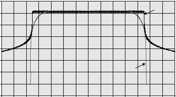
Figure 4.16 Spectrum of a basic 5 MHz OFDM signal compared with WCDMA spectrum.
4.8.2 Number of subcarriers
Once the subcarrier spacing has been selected based on environment, expected Doppler spread and time dispersion, etc., the number of subcarriers can be determined based on the amount of spectrum available and the acceptable out-of-band emissions.
The basic bandwidth of an OFDM signal equals Nc · f , i.e. the number of subcarriers multiplied by the subcarrier spacing. However, as can be seen in Figure 4.16, the spectrum of a basic OFDM signal falls off very slowly outside the basic OFDM bandwidth and especially much slower than for a WCDMA signal. The reason for the large out-of-band emission of a basic OFDM signal is the use of rectangular pulse shaping (Figure 4.1), leading to per-subcarrier side lobes that fall off relatively slowly. However, in practice, straightforward filtering or time-domain windowing [117] will be used to suppress a main part of the OFDM out-of-band emissions. Thus, in practice, typically in the order of 10% guard-band is needed for an OFDM signal implying, as an example, that in a spectrum allocation of 5 MHz, the basic OFDM bandwidth Nc · f could be in the order of 4.5 MHz. Assuming, for example, a subcarrier spacing of 15 kHz as selected for LTE, this corresponds to approximately 300 subcarriers in 5 MHz.
4.8.3 Cyclic-prefix length
In principle, the cyclic-prefix length TCP should cover the maximum length of the time-dispersion expected to be experienced. However, as already discussed,
60 |
3G Evolution: HSPA and LTE for Mobile Broadband |
increasing the length of the cyclic prefix, without a corresponding reduction in the subcarrier spacing f , implies an additional overhead in terms of power as well as bandwidth. Especially the power loss implies that, as the cell size grows and the system performance becomes more power limited, there is a trade-off between the loss in power due to the cyclic prefix and the signal corruption due to time dispersion not covered by the cyclic prefix. As already mentioned, this implies that, although the amount of time dispersion typically increases with the cell size, beyond a certain cell size there is often no reason to increase the cyclic prefix further as the corresponding power loss would have a larger negative impact, compared to the signal corruption due to the residual time dispersion not covered by the cyclic prefix [15].
One situation where a longer cyclic prefix may be needed is in the case of multicell transmission using SFN (Single-Frequency Network), as further discussed in Section 4.11.
Thus, to be able to optimize performance to different environments, some OFDMbased systems support multiple cyclic-prefix lengths. The different cyclic-prefix lengths can then be used in different transmission scenarios:
•Shorter cyclic prefix in small-cell environments to minimize the cyclic-prefix overhead.
•Longer cyclic prefix in environments with extreme time dispersion and especially in case of SFN operation.
4.9Variations in instantaneous transmission power
According to Section 3.3.1, one of the drawbacks of multi-carrier transmission is the corresponding large variations in the instantaneous transmit power, implying a reduced power-amplifier efficiency and higher mobile-terminal power consumption, alternatively that the power-amplifier output power has to be reduced with a reduced range as a consequence. Being a kind of multi-carrier transmission scheme, OFDM is subject to the same drawback.
However, a large number of different methods have been proposed to reduce the large power peaks of an OFDM signal:
•In case of tone reservation [78], a subset of the OFDM subcarriers are not used for data transmission. Instead, these subcarriers are modulated in such a way that the largest peaks of the overall OFDM signal are suppressed, allowing for a reduced power-amplifier back-off. One drawback of tone reservation is the
OFDM transmission |
61 |
bandwidth loss due to the fact that a number of subcarriers are not available for actual data transmission. The calculation of what modulation to apply to the reserved tones can also be of relatively high complexity.
•In case of pre-filtering or pre-coding, linear processing is applied to the sequence of modulation symbols before OFDM modulation. DFT-spread- OFDM, to be described in the next chapter, can be seen as one kind of pre-filtering.
•In case of selective scrambling [23], the coded-bit sequence to be transmitted is scrambled with a number of different scrambling codes. Each scrambled sequence is then OFDM modulated and the signal with the lowest peak power is selected for transmission. After OFDM demodulation at the receiver side, descrambling and subsequent decoding is carried out for all the possible scrambling sequences. Only the decoding carried out for the scrambling code actually used for the transmission will provide a correct decoding result. A drawback of selective scrambling is an increased receiver complexity as multiple decodings need to be carried out in parallel.
Readers are referred to the references above for a more in-depth discussion on different peak-reduction schemes.
4.10OFDM as a user-multiplexing and multiple-access scheme
The discussion has, until now, implicitly assumed that all OFDM subcarriers are transmitted from the same transmitter to a certain receiver, i.e.:
•downlink transmission of all subcarriers to a single mobile terminal;
•uplink transmission of all subcarriers from a single mobile terminal.
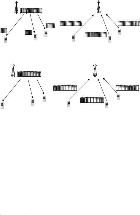
However, OFDM can also be used as a user-multiplexing or multiple-access scheme, allowing for simultaneous frequency-separated transmissions to/from multiple mobile terminals (see Figure 4.17).
In the downlink direction, OFDM as a user-multiplexing scheme implies that, in each OFDM symbol interval, different subsets of the overall set of available subcarriers are used for transmission to different mobile terminals (see Figure 4.17a).
Similarly, in the uplink direction, OFDM as a user-multiplexing or multiple-access scheme implies that, in each OFDM symbol interval, different subsets of the overall set of subcarriers are used for data transmission from different mobile terminals
62 |
3G Evolution: HSPA and LTE for Mobile Broadband |
(a) |
(b) |
Figure 4.17 OFDM as a user-multiplexing/multiple-access scheme: (a) downlink and (b) uplink.
(a) |
(b) |
Figure 4.18 Distributed user multiplexing.
(see Figure 4.17b). In this case, the term Orthogonal Frequency Division Multiple Access or OFDMA is also often used.4
Figure 4.17 assumes that consecutive subcarriers are used for transmission to/from the same mobile terminal. However, distributing the subcarriers to/from a mobile terminal in the frequency domain is also possible as illustrated in Figure 4.18. The benefit of such distributed user multiplexing or distributed multiple access is a possibility for additional frequency diversity as each transmission is spread over a wider bandwidth.
In the case when OFDMA is used as an uplink multiple-access scheme, i.e. in case of frequency multiplexing of OFDM signals from multiple mobile terminals, it is critical that the transmissions from the different mobile terminals arrive approximately time aligned at the base station. More specifically, the transmissions from the different mobile terminals should arrive at the base station with a timing
4 The term OFDMA is sometimes also used to denote the use of OFDM to multiplex multiple users in the downlink as illustrated in Figure 4.17a.

OFDM transmission |
|
|
|
63 |
|
|
Without time alignment |
With time alignment |
|
|
|
UE #1 |
|
|
|
UE transmission UE #2 |
|
|
|
UE #1 |
UE #2 |
UE #1 t1 |
|
|
|
BS reception |
|
|
|
|
UE #2 |
t2 |
|
|
|
|
|
||
|
|
|
t2 t1 |
|
(a) |
|
(b) |
|
(c) |
Figure 4.19 Uplink transmission-timing control.
misalignment less than the length of the cyclic prefix to preserve orthogonality between subcarriers received from different mobile terminals and thus avoid inter-user interference.
Due to the differences in distance to the base station for different mobile terminals and the corresponding differences in the propagation time (which may far exceed the length of the cyclic prefix), it is therefore necessary to control the uplink transmission timing of each mobile terminal (see Figure 4.19). Such transmittiming control should adjust the transmit timing of each mobile terminal to ensure that uplink transmissions arrive approximately time aligned at the base station. As the propagation time changes as the mobile terminal is moving within the cell, the transmit-timing control should be an active process, continuously adjusting the exact transmit timing of each mobile terminal.
Furthermore, even in case of perfect transmit-timing control, there will always be some interference between subcarriers e.g. due to frequency errors. Typically this interference is relatively low in case of reasonable frequency errors, Doppler spread, etc. (see Section 4.8). However, this assumes that the different subcarriers are received with at least approximately the same power. In the uplink, the propagation distance and thus the path loss of the different mobile-terminal transmissions may differ significantly. If two terminals are transmitting with the same power, the received-signal strengths may thus differ significantly, implying a potentially significant interference from the stronger signal to the weaker signal unless the subcarrier orthogonality is perfectly retained. To avoid this, at least some degree of uplink transmit-power control may need to be applied in case of uplink OFDMA, reducing the transmit power of user terminals close to the base station and ensuring that all received signals will be of approximately the same power.
4.11Multi-cell broadcast/multicast transmission and OFDM
The provisioning of broadcast/multicast services in a mobile-communication system implies that the same information is to be simultaneously provided to multiple mobile terminals, often dispersed over a large area corresponding to a large number of cells as shown in Figure 4.20. The broadcast/multicast information may be a TV news clip, information about the local weather conditions, stock-market