

Innovative power engineering
..pdfIn this paper, we present a model of magnetically coupled resonators in terms of passive circuit elements and derive system optimization parameters. In addition, an analysis of system transmission characteristics, with single load and multi load, is elaborated in forms of the impacts of system load and transmission distance on transmission system output load and efficiency in respectively. In wireless power transmission experiment, the experiment results are in accordance with the theory we expounded. This is important from a practical standpoint because, in many applications, such as laptop recharging, the range and orientation of the receive device with respect to the transmit device vary with user behavior.
1. System analysis and circuit model
Magnetically resonant coupling wireless power transmission technology (MCR-WPT) is the use of two coils for the same resonance frequency, electromagnetic coupling produces an alternating magnetic field of the same frequency, and the receiving device continues to gather energy to the load, thus achieving a high efficiency of wireless power transmission.
Magnetically coupled resonant wireless power transmission system structure shown in Fig. 1, the Class E high-frequency inverter circuit is used for a system frequency driver source, the power transmitting coil LP will come out power in the form of electromagnetic radiation in the near field received by receiving coil LS, the magnetic coupling distance between the two transmission coils for D.
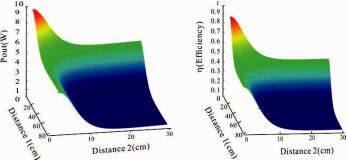
Fig. 4. System output power and efficiency versus transmission distance and load
151
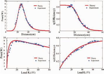
Fig. 5. Power and efficient versus distance and load in theory and experiment
At high frequencies, the transmission coil LP and LS have parasitic capacitance, the small capacitance value cannot compensate the two transmission coils to achieve a resonant state, therefore one need to compensate a capacitor Ca and Cb in series to transmit and receive circuits respectively, so that both ends of the transmitter and receiver circuits are in resonant state, working in the strong coupling resonance condition, to ensure the system to achieve optimal transfer efficiency and load maximum transmit power.
According to Fig. 2, using circuit theory, we deduct the wireless power transmission system equivalent circuit model to calculating transmission formula. According to KVL formula, the coil circuit current iP and iS in LP and LS respectively are:
IP |
|
ZSUS |
, |
|||
ZP ZS |
( M )2 |
|||||
|
|
(1) |
||||
|
|
j MUS |
||||
IS |
|
|
. |
|||
ZS ZP |
( M )2 |
|
||||
|
|
|
|
|||
152
According to formula(1), the desired optimum transmission distance D as follows can be obtained when the receiving side of the load is constant, in order to ensure that the output impedance of the class E inverter circuit is also a constant value:
|
|
2 f |
N 2r4 |
|
|
(2) |
|
D 3 |
|
|
0 |
|
. |
||
Z |
in |
R R R |
|
||||
|
|
|
L |
|
|
|
|
When the receiving end is connected with a given load at a certain distance, E class high frequency inverter output terminal impedance Zin is:
Zin R |
4 f 2 02 N 4r8 |
. |
(3) |
|
R RL D6 |
||||
|
|
|
At higher QL, sinusoidal harmonic components of load are lower, but the efficiency of the converter will be reduced. At lower QL, the converter can work in the higher efficiency state, but the harmonic components of the output sine wave are higher. QL when we choose, we must take into account these two factors. In general we choose QL from 5 to 10. The other parameters can be measured by quality factor QL.
According to the parameter optimization theory, load RL is 20•, MOSFET drive voltage frequency is 1MHz, pulsation amplitude is 6V, pulse period is 1000ns, and pulse width is 50ns. Make class E inverter in the best condition, namely to achieve zero-voltage switch opening. Final adjusted parameters L2, C1, C2 shown in Table 1. According to the formula for calculating the coil inductance, resistance, and inductance of the coil itself specifications can be obtained parameters are given in Table.
When the wireless transmission network receiving end connected to 20• purely resistive load, according to the formula (2), (3) the best load state can be obtained that the transmission distance is set to 23cm, and the output terminal of the inverter circuit E class is load of 20•.
2. The effect of transmission distance and load on output power and efficiency
According to above section, we set up the experimental platform, using parameters in table. The experimental results as shown in fig. 3,
153
(a) is high frequency switcher driver voltage, MOSFET voltage and current waveforms, (b) is receiving end load waveform. The Waveform vs is switcher voltage, is is switcher current, vg is driving voltage. It can be observed that the power under the working frequency of 1 MHz can achieve soft switch. vL and iL are voltage and current of the load at receiving end. Wireless power transmission system can stably work under 23cm distance at 1MHz.We can use this WPT system to smart home environment with multiple loads. Under this application condition, the system should be optimized for complex load change, with matching high-frequency power source output impedance to multiple loads network. The influence of coupling magnetic field block by building and furniture also needs to be taken into account.
With the success of wireless power transmission in our experimental platform, the next step is that analysis the impact of parameters in wireless power transmission on system output power and efficiency, in respectively, such as transmission distance, load, etc. As the above analysis, the system output power can be calculated as formula (4).
|
|
|
|
R U 2 |
( M )2 |
|
|
||
PO |
|
|
|
|
L S |
|
|
. |
(4) |
R |
R |
R |
|
M 2 2 |
|||||
|
|
|
P |
S |
L |
|
|
|
|
In this experimental condition, emission coil circuit and receiving coil circuit are in resonance condition in 1MHz transmission frequency, so the circuit impedance can be simplified to emission circuit resistance and receiving resistance, and in this paper, we only analysis the resonance working condition in which the wireless power transmission system works as the maximum output power and efficiency, so it is the most useful and the most practical condition we use the transmission system.
The high frequency power loss resistance in emission and receiving circuit has two forms: ohmic loss resistance R0 and radiation loss resistance Rf. In magnetically resonant coupling wireless power transmission system, the radiation loss resistance Rf is far less than ohmic loss resistance R0, so that the radiation loss resistance can be
154
neglected, and high frequency power loss can only be simplified to ohmic loss resistance R0. As the above analysis, the system output efficiency can be calculated as formula (5).
|
|
|
|
R ( M )2 |
|
|
|
|||
|
|
|
|
|
L |
|
|
|
100 %. |
(5) |
R R |
R |
R R |
M 2 |
2 |
||||||
|
|
|
|
|||||||
0 |
L |
|
0 |
0 |
L |
|
|
|
|
|
As the formula (4, 5), the impact of transmission distance D and load RL on transmission output power and efficiency is illustrated in Fig. 4.
Fig. 6. System output power and efficiency versus two load transmission distance.
As the Fig. 4 shown, first figure describe the output power versus transmission distance and load. At any distance, output power increase as load increase. Under optimization load resistance 20 , output power is very low, in the other hand, when the load resistance beyond optimization load, output power can keep in a maintain state 9W. As the transmission increase from 0 to 80 , output power increase to a maximum point and then decrease to zero with a maximum output power point appearance at about the optimization distance 23cm. In the second figure, as load increase from zero, transmission system efficiency increase in a high speed, and then keep in a maintain state about 80%. Like to the impact of distance on output power, the system efficiency increase in a high speed to a maximum point and then decrease slow down as distance increasing from zero.
155
As the above analysis, optimization load resistance is 20• and optimization transmission distance is 23 cm. The experiments were carried out in two cases: in the first condition, system load is fixed in optimization load resistance 20•, the system output power and transmission efficiency are tested in varied coil distance; in the second condition, transmission distance is fixed in optimization coil distance 23 cm, the system output power and transmission efficiency are tested in varied system load resistance.
In constant system optimization load, transmission output power has a maximum point in optimization distance 23cm, and the maximum output power is 9W; system efficient decrease with transmission distance increasing. When the distance is under 20cm, the system efficiency is maintained in about 85 %. The efficiency decreasing rapidly from 80 to 10 % with distance increasing from 20cm to 40 cm, and then efficiency is gradually approaching to zero. At optimization distance 23 cm, system efficiency is only about 70 %. When system load is optimization load, the maximum output power and system transmission efficiency don’t appearance at the same transmission distance, so that the practical transmission distance one used is cooperating with utilization requirement and condition.
In constant optimization transmission distance, transmission output power has a maximum point in optimization system load 20•, and the maximum output power is 9W. When the system load is under 20•, the output power increasing rapidly from 0 to 9W with distance increasing from 0 to 20•, and then the output power is maintained in about 8W. System efficient increases from 0 to 0.7 with system load increasing from 0 to 80•. At optimization load 20•, system efficiency is only about 40 %. When transmission distance is optimization load, the maximum output power and system transmission efficiency don’t appearance at the same system load, so that the practical system load one used should be cooperating with utilization requirement and condition.
According to equivalent circuit model with single load, emission coil circuit current and receiving coil circuit current can be derived in multi load transmission system.
156
IS |
|
|
|
|
|
|
|
|
US |
|
|
|
, |
|
|
|
|
|
|
2 |
2 |
3 |
|
|
|||
|
|
!ZS |
|
M1 Z2 j M1M2M12 |
" |
|
|||||||
|
|
|
|
||||||||||
|
|
! |
|
|
|
|
|
|
Z1Z2 2M122 |
" |
|
||
|
|
! |
|
|
2 |
M |
2 |
3 |
|
|
" |
|
|
|
|
! |
|
2 Z1 |
j M1M2M12 |
" |
|
||||||
|
|
! |
|
|
|
|
|
|
2 |
2 |
|
" |
|
|
|
# |
|
|
|
|
|
Z1Z2 |
M12 |
$ |
|
||
I |
2M2M12 j M1Z2 |
|
I |
, |
|||||||||||
|
|
||||||||||||||
1 |
|
|
Z Z |
2 |
2M 2 |
|
|
S |
|
||||||
|
|
|
1 |
|
|
|
|
12 |
|
|
|
|
|||
|
|
|
|
2M |
1 |
M |
12 |
j M Z |
|
|
|
||||
I |
|
|
|
|
|
|
|
|
|
2 1 |
|
I |
. |
||
|
|
Z Z |
|
|
2M 2 |
|
|
||||||||
|
2 |
|
|
2 |
|
|
|
S |
|
||||||
|
|
|
1 |
|
|
|
|
|
12 |
|
|
|
|
||
(6)
(7)
(8)
As formula (6), (7), (8), the system transmission efficiency and output power can be derived.
P I 2 R |
I 2 R |
, |
(9) |
||
|
1 L1 |
|
2 L2 |
|
|
|
P |
|
100 %, |
(10) |
|
US IS cos% |
|||||
As the formula 8, 9, the impact of two loads transmission distance D1 and D2 on transmission output power and efficiency is illustrated in Fig. 6.
As the Fig. 6 shown, output power increase as two load transmission distance increase. Under optimization load resistance 20 , in the transmission distance 10 to 20 cm range, output power is around 5 W to 6 W, and system efficient is about 50 %. It is a practical output power and efficiency and can be used is actual application. When the two load transmission distance increase, the output power and efficiency decrease rapidly, so it is better to use in the optimal transmission range from 10 to 20 cm for the actual application.
Conclusion
In this paper, we present a model of magnetically coupled resonators in terms of passive circuit elements and derive system
157
optimization parameters. In addition, an analysis of system transmission characteristics, with single load and multi load, is elaborated in forms of the impacts of system load and transmission distance on transmission system output load and efficiency in respectively. In wireless power transmission experiment, the experiment results are in accordance with the theory we expounded. This is important from a practical standpoint because, in many applications, such as laptop recharging, the range and orientation of the receive device with respect to the transmit device vary with user behavior.
References
1.Wireless power transfer via strongly coupled magnetic resonances / A. Kurs, A. Karalis, R. Moffatt [et al.] // Science. – 2007. – Vol. 317(5834). – P. 83–86.
2.Karalis A., Joannopoulos J.D.* ‚[gƒd„_… † ‡aa_Z_X`V ˆ_cXgX^^ `[`-
radiative mid-range energy transfer // Annals of Physics. – 2008. – Vol. 323(1). – P. 34–48.
3.Tesla N. Apparatus for transmitting electrical energy: U.S. Patent 1,119,732. 1914-12-1.
4.Sample A.P., Meyer D.A., Smith J.R. Analysis, experimental results, and range adaptation of magnetically coupled resonators for wireless power transfer // IEEE Transactions on Industrial Electronics. – 2011. – Vol. 58(2). – P. 544–554.
5.Hirai J., Kim T.W., Kawamura A. Wireless transmission of power and information and information for cableless linear motor drive // Power Electronics, IEEE Transactions on. – 2000. – Vol. 15(1). – P. 21–27.
6.Magnetic resonant coupling as a potential means for wireless power transfer to multiple small receivers / B.L. Cannon, J.F. Hoburg, D.D. Stancil [et al.] // Power Electronics, IEEE Transactions on. – 2009. – Vol. 24(7). – P. 1819–1825.
7.Kurs A., Moffatt R.* ‚[gƒd„_… † ‚_\fgVd`X[f^ \_i-range power
transfer to multiple devices // Applied Physics Letters. – 2010. – Vol. 96(4). –
P.044–102.
8.Joannopoulos J.D., Karalis A., Soljacic M. Wireless non-radiative energy transfer: U.S. Patent 7,741,734. 2010-6-22.
158
9.Contactless power and information transmission / T. Bieler, M. Perrottet, V. Nguyen [et al.] // IEEE Transactions on Industry Applications. – 2002. – Vol. 38(5). – P. 1266–1272.
10. |
, |
, |
. |
ġ// |
|
|
. – 2013. – Vol. 33(3). – P. 1–13. |
|
|
11. Kim J., Son H.C., Kim D.H., Park Y.J. Optimal design of a wireless power transfer system with multiple self-resonators for an LED TV // IEEE
Transactions on Consumer Electronics. – 2012. – Vol. 58(3). – P. 775–780. |
|
||||
12. |
, |
, |
, . |
|
ġ// |
|
|
. – 2012. – Vol. 32(12). – P. 155–160. |
|
|
|
13. |
, |
|
, |
, |
. |
|
|
|
ġ // |
. |
– |
159
THE IMAGINE ABOUT THERMOELECTRIC POWER
GENERATION GLASS
Hongrui Peng, Heping Liu
Thermoelectric power generation is an environment-friendly power source which can rationally use the low-grade heat energy such as solar heat, geothermal energy, industrial waste heat and so on, to generate electricity. In order to take better advantage of the solar heat, an idea to create a kind of thermoelectric power generation glass was introduced. Referring to solar glass, the thermoelectric materials are inserted into two layers of the glass. The feasibility of the thermoelectric power generation glass was analyzed, and the cost analysis was mentioned. With the performance improvement of the thermoelectric materials and modules, thermoelectric power generation glass will have a broad prospect.
Keywords: thermoelectric materials, Thermoelectric power generation, innovation glass, Glass curtain wall.
1. The Principle of Thermoelectric Power Generation
Thermoelectric effect is the general term of the thermal effects from electric effect and the current-caused temperature difference, including seebeck effect, peltier effect and thomson effect [1–3]. These three effect can be connected by kelvin relationship.
A. Seebeck Effect
Seebeck effect was first discovered by the German physicist Thomas Seebeck in 1823. It is the ability to transfer heat into electricity. When there is temperature difference at the junction of a closed loop, which is formed by two different conductors, the loop will generate a current. Shown in Fig. 1.1, when connectors 1 and 2 maintain at different temperatures, denoted as T1 and T2 (T1 > T2), it will produce electrical potential difference between the two ends of the conductor (y and z). The electrical potential difference is named as Vs, which is the thermal electromotive force. Value Vs can be expressed as:
Vsh ab T1 T2
160