

Innovative power engineering
..pdfconsumption, being operated at atmospheric pressure, low requirements for seawater pretreatment, lower humidifying temperature (<100 °C), not easily scaling, and low investment. In recent years, this method is to attract the attention of the scholars in the Middle East, North Africa, the United States, Australia and China, etc., but the technology of it still has much space for improvement [2]. The main factors affected HDH desalination technology are humidifying efficient, recovery efficient of water vapor condensation latent heat, and the advanced process with low power consumption and high gain output ratio (GOR).
The traditional humidifying process uses spray method. The rate of three stages traditional spray humidifying is about 96 %. From the year of 2012 to 2013, G. Prakash Narayan, etc. [3–4] used packed tower spray humidifying technology, which humidifying rates reached to 98–100 %. But the surface of filler was easy scaling, and the flow resistances of water and air were increased.
However, the surface of filler was easy by scaling, and the packing in tower leads to the increasing of flow resistances for the water and air, and the increasing of energy consumption for producing freshwater. In 2008, SAEl-Agouz [5] et. al. of Egypt, who first put porous air pipe into the seawater, which made the air bubbling humidifying rate reached 95 %. In the end of 2008, a single-stage sieve bubbling humidifier was developed by our research group, its humidifying rate could reach 100 %. The humidifier had many other advantages, such as simple structure, small size, making by non-toxic plastic, disassembling and cleaning easily, which solved the problems of seawater corrosion and descaling for humidifier [6].
At present, there are three main methods of condensation latent heat recovery of water vapor in desalination process: preheating sea water, direct evaporation of seawater and heat storage reuse. As for preheating sea water method, the unit is simple, easy to implement and it’s more general, but only about 1/7–1/10 of the preheated water is used to supplement the consumption of the sea water in the unit, while the remaining preheated sea water due to that its low grade heat can not be reused, only to be discharged, so the total heat recovery utilization is
111
low; the heat storage recycling, high heat capacity of heat storage medium is required [7], to quickly endothermic and exothermic [8] , but the current level of technology is still hard to satisfy the above requirements; direct evaporation of sea water, of which the thermal recovery efficiency is high, is the main direction of development in latent heat of condensation recycling aspect, but it’s limited by the design and equipment performance. The application developed in such a process [9–11], mainly using the light and heat of solar energy, generally recovering latent heat of condensation of water vapor in the form of natural convection heat transfer.
In 2013, our group designed a solar desalination process in which a single-stage bubble humidification was coupled with stack plates. The humidifier structure was simple, and the sieve was easy to disassemble, what’s more, making by non-toxic plastic, solving the seawater corrosion resistance and fouling problems; only air circulation flowed during the process and the energy consumption was low. Studies had shown that single-stage sieve bubbling humidifier rate can reach 100 %, higher than other wet methods; the higher the humidity temperature and the amount of solar radiation were, the greater the production of water was; the less resistance of air flow was; the lower the production cost of water was. When humidification temperature was in the range of 40 °C to 70 °C, each increase of 10 °C, the air saturated water content increased by about 1 times; when it rose from 70 °C to 90 °C, the air saturated water content increased by about four times [2].
In this article, the working process of the solar desalination unit is described, the humidification-dehumidification experimental system is established, and the main affecting factors for the water production are studied and analyzed.
Process flow
As shown in Fig. 1, the unit consists of solar collector, bubbling humidification dehumidifier, fresh water collector, fan, pump, valves and pipes.
112
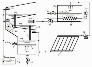
Fig. 1. Solar desalination flow sheet of bubbling humidifying coupled with stack plates dehumidifying: 1. solar collector; 2. sea discharge valve; 3. storage tank; 4. sieve plate; 5. brine discharge valve; 6. overflow tube; 7. stack plate; 8. bubbling humidifier-dehumidifier; 9. fresh water collector; 10. check valve;
11.fresh water discharge valve; 12. re-dehumidifier; 13. seawater pre-heater;
14.spray; 15. seawater bump; 16. fan
The air driven by fan is heated by the solar air collector, and then enters into bubbling humidifier being humidified to the saturated wet vapor state. The saturated air flow upward, which is partially condensed on the bottom surface of the first stage aluminum plate, the freshwater is gotten, and the latent heat of water vapor condensation is released; and then the cold sea water above the stack plate is heated. After passing the first stage, the hot and wet air continues to flow along the air channel between the first and second stage, it is condensed some freshwater on the bottom surface of the second stage stack plate, and releases the condensation latent heat, which is absorbed by the seawater on the second stage stack plate. Sunlight through the top glass cover on the second stage stack plate, the air above the second stage plate is heated, and humidified. The wet air is cooled and partial condensed on the bottom surface of glass, and get another part of freshwater. The freshwater obtained at every stage finally is collected into fresh water
113
tank. Cooled and dehumidified air flows from the bubbling humidifierdehumidifier into the re-dehumidifier, in which it further be condensed to get a portion of freshwater. Then the air flows into the fan for the next cycle. Seawater flowed into the system through the sea water pump pressures into the cooling tank to be preheated, intermittently added into the second stage stacked plate of the bubbling humidifier dehumidifier. When the level rises above the overflow pipe surface height, automatically flows down the overflow pipe to next stage. There is a liquid level sensor above the sieve, connecting to a liquid level control solenoid valve. When the liquid level reaches a certain height, the valve will automatically close and stop filling seawater. When the level falls below a certain height, the valve automatically opens starting to fill water. Bubbling humidifier dehumidifier periodically discharged brine to keep the seawater in the humidifier is maintained within a certain range.
Experimental system
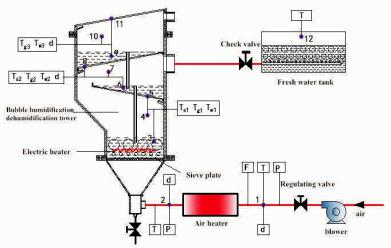
Bubbling humidification dehumidification stack plate experiment system is shown in Fig. 2, mainly composed of bubbling humidifier dehumidifier, air heater, water and electricity heater, fan, fresh water cooling tank, experiment instruments and other components. During the experiment, a finned tube heater was used to simulate solar air collector to heat air, and the annular electric heater was placed in the sieve of the water layer to heat sea water. Air flow was adjusted by the ball valve and measured with a pilot tube flow meter; air humidity with digital temperature and humidity meter; each measuring point temperature with digital temperature sensor or thermo-couple thermometer. The maximum conveying air volume of the fan was 35 m3/h, and the sieve water layer temperature adjusted from 0 to 100 °C.
Results and analysis of the experiments
The experiments were carried out in Xi'an of China in December 2014. The measurement parameters included: total water production of the whole unit, each stage of stack plates’ water productions, the temperature, humidity and pressure of ambient air, the air temperature, humidity and air flow in the inlet and outlet of dehumidifier
114
humidification, the temperatures of two stages’ water and air inside the bubbling humidifier dehumidifier, in addition, the temperature at the bottom of the stack was also measured.
Fig. 2. Bubbling humidifying coupled with stack plates unit
(1) The changes of parameters in pilot experiment
During the experiment, the indoor air temperature was taken as 24.2 °C, relative humidity12.7 %, atmospheric pressure 0.9746 MPa. Water temperature on the sieve was automatically controlled by the mode of constant temperature electric heating. The water temperature was respectively taken as 50 °C, 60 °C, 70 °C. The wet air temperature leaving the sieve was equal to the water temperature on the sieve. The seawater stored on the first stage stack plate was 9.87 kg, and the second stage was 8.68 kg.
20 minutes later, the freshwater started to precipitate. Then all levels of water and air temperatures and the water production were measured every 2 min. The relationships about these parameters changing with time were shown in Fig. 4 to Fig. 6. As was shown in Fig. 7, in the initial stage operation of the unit, water productions of the first and the second stages showed a rapid increase with time going. And the first stage of water production was always higher than the second one.
115
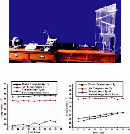
Fig. 3. The picture of bubbling humidifying coupled with stack plates unit
Fig. 4. Air and water temperatures |
Fig. 5. Temperatures changing |
on the sieve |
on the first stage stack plate |
As was shown in Fig. 8, both water temperature and air temperature were in a dynamic process in initial equipment operation, and the temperatures of water and air were shown in a descending trend from the sieve up to the second stage. In the case of a constant supply of heat and ignoring the heat loss, the air temperature and water temperature of each stage will reach the same, if run in an unlimited long time according to Fig. 8.
116
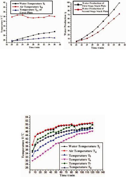
Fig. 6. Temperatures changing |
Fig. 7. Water production changing |
on the second stage stack plate |
with time |
(2) The influence of the water layer height above sieve on water production
Experimental conditions are: ambient air temperature was 23 ~ 25 °C, air relative humidity 29.5 %, atmospheric pressure P0 = = 0.9746 MPa, sieve aperture d0 = 2 mm, mesh number n = 144, maximum air supply of fan 35 m3/h, bubbling humidifying temperature 50 °C. When the height of water layer above the sieve respectively was 4 cm, 6 cm and 8 cm, the first and the second stack plate’s water productions were recorded 20 min later as shown in Fig. 9 and Fig. 10.
Fig. 8. Temperatures of measurement points changing with time
117
Experiment showed that when the water layer height increased from 4cm to 8cm, air relative humidity can both reach 100 % and no leakage of water; with the height of water layer increasing, water production was declined. The reason was that as the height of the water layer increased, bubbling humidifying air resistance increased, the actual air supply of fan was reduced. Although the relative humidity was still 100 %, the reduction amount of wind resulted in a decrease of total water production. Therefore, under the premise of meeting humidification rate of 100 % during the actual humidification process, the height of the water layer should be reduced as far as possible. Under conditions of this research project, the water layer height in the range of 4cm to 6cm was more reasonable.
(3)The influence of inclination angle of stack plate on water production
Through the experimental condition that the stack plate inclination angles were taken as 10°, 15° and 30°, a conclusion was drawn that an appropriate increase in the inclination angle of the stack plate contributed to the slide and collection of condensate water generated by moist air on the surface of the stack plate; brushing hydrophobic coating at the bottom surface of the stack plate can accelerate condensate accumulation and fall. Thereby it increased the amount of fresh water collection, reduced surface film resistance over the stacked plate and improved wet air condensing heat transfer effect. However, the increasing tilt angle will result in higher dimension of humidification dehumidifier. In summary, stack plate tilt angle in the range of 15-30° is more reasonable.
(4) With humidification dehumidification process going, the amount of sea water on the sieve and all levels of stack plate will be reduced. In order to maintain the larger sea water evaporation area of the inclined surface, avoid that water concentration in the stack plate is too high, and maintain the temperature difference between the bottom of the stack tray and moist air, new seawater was needed to add regularly into the sieve and stack plates. The larger temperature difference between the bottom of the stacked plate and the wet air was, the faster moist air condenses and the higher water production rate was.
118
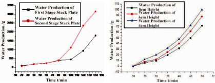
Fig. 9. Water production of the first |
Fig. 10. Water production of the |
stage stack plate changing with time |
second stage stack plate changing |
|
with time |
(5) Water production ratio GOR
The energy consumed in the desalination unit can be electricity, heat, industrial waste heat and solar energy and so on. Performance evaluation of water production unit usually uses water production ratio GOR (gain output ratio) indicator, whose definition is that the ratio of the product of the amount of freshwater production M (kg/h) and water vaporization latent heat ! (kJ/kg) to the sum of all kinds of energy consumption during the production process E (kW), as seen in Eq. (1):
GOR |
M ! |
|
M ! |
, |
(1) |
|
|
||||
|
3600E |
3600 (N P) |
|
||
where N is the pump power consumption, kW; P is the fan power consumption, kW.
As shown in Fig. 7 and Fig. 11, after running 20 minutes, the unit began to produce water. When it ran between 20 min to 80 min, the difference of water production between the first stack plate and the second one was not obvious; after 80 min, the water production increased significantly. From 20 to 140min, the first stage stack plate water production was 1.6 kg/h, the second one was 0.9 kg/h, and the total water production of the device was 2.7 kg/h. The power consumption of the pump N and the fan P were 0.3 kW and 0.15 kW. Assuming that the water and air on the sieve plate were all heated by
119
solar energy, from the equation (1), it was calculated that the GOR of the unit was 4. The cost of water production was 12.2 Yuan (RMB)/t, if the price of electricity power is 0.49Yuan (RMB)/kWh.
Influence factors that resulted in the difference between the theoretical water production and the actual one were as follows: Firstly, there was temperature difference between internal and external of the unit, it resulted in that a part of the internal heat lost to the environment; secondly, some amount of fresh water dropped to the lower water pan resulting in the loss of water production; part of freshwater condensed around the walls of humidifier-dehumidifier, it had not been recovered; condensed water adhering to the surface of stack plate which caused a reduction in the coefficient of condensation heat transfer, and the moist air condensed insufficiently.
Conclusions
It introduces a novel solar desalination process of bubbling humidifying coupled with stack plates dehumidifying, and the HDH experimental system of it. Through experiments and theoretical analysis, some conclusions are drawn:
1)In the preconditions of certain bubbling humidification temperature and fan flow, the height of the water layer on the sieve, stacked plate tilt angle, temperature difference between the bottom surface of the stack plate and moist air and other parameters are the main factors affecting water production performance.
2)Under the condition of the humidification rate reaching to 100 %, the water layer height on the sieve should be reduced as much as possible, thus the power consumption of the fan can be reduced. In this research, the water layer height is more reasonable in the range of 4cm to 6cm.
3)Appropriate increasing in the inclination angle of the stack plate and brushing hydrophobic coating on the bottom surface of the stack plate could accelerate the water droplets accumulation, slide and collection. This research indicates that the reasonable tilt angle of it is in the range of 15–30°.
120