

Mechanical Properties of Ceramics and Composites
.pdf460 |
Chapter 8 |
Similar closed form expressions are given for bulk and shear moduli, as well as Poisson’s ratio. Good agreement was shown with data, e.g. for WC-Co bodies. While there are other bound expressions, it will be shown later that limited trials of the above-noted expressions give reasonable results (e.g. Fig. 8.11), as does the obvious use of the average of Eqs. (8.3) and (8.4), which is suitable for most present purposes.
Modeling to give even more rigorous expressions rather than bounds (even if relatively close) has been extensively conducted, but while substantial progress has been made, there are still important issues because of the simplifications and idealizations generally required to treat such complex problems rigorously. Thus models typically assume an isotropic matrix with isotropic inclusions of a single, simple shape, typically of uniform size, and no specification of its spatial distribution other than generally being uniform. Many models assume explicitly or implicitly a dilute dispersion of second phase, i.e. so interactions between adjacent particles can be neglected. Shapes are most commonly assumed to be spherical, but spheroids (and hence in the extreme rods) as well as platelets and needles have been considered, which can be important [4-6].
Many of the more rigorous models, which often do not give simple closed form expressions [e.g. as in Eqs. (8.1) through (8.4)], fall into one of the three following categories: (1) differential, (2) generalized self-consistent (GSC), and
(3) Mori–Tanaka (M–T) approaches to the problem. Such models often give only bulk modulus rigorously, and sometimes also shear modulus, but generally Young’s modulus and Poisson’s ratio, and sometimes also shear modulus, can only be estimated, e.g. via bounding techniques. Christensen [7] reviewed the applicability of the above three model types for spherical particles, showing that while all three generally agreed with each other and data to φ = 0.2–0.5, there was significant divergence at higher φ values, with the GSC method giving the best agreement with data. The other two models varied substantially in their degree of agreement and disagreement with each other, the GSC results, and data. Note that the advantages of the GSC method for such composites were achieved only after improvements to the forerunner self-consistent method (SCM) were made, since the SCM was not always accurate over the full range of φ. Much of the ground work for the SCM was laid by Hashin [8].
Further note that the above models and most or all other models are of uncertain applicability as the size of the filler particles is no longer constant, and especially as their shape changes from spherical to more irregular or elongated shapes, though again there are special models for important idealized shapes such as discs, rods (fibers), and needles. An important problem for some particulate, whisker, and especially platelet ceramic composites is the combined issues of shape, elastic anisotropy, and varying (usually poorly characterized) degrees of preferred orientation. Finally note that many models are primarily or exclusively applicable to two-phase composites, while many composites contain three
Particle (and Grain) Effects |
461 |
or more phases (e.g. concrete and some composites noted later). While a number of models can be modified to make estimates for such multiphase composites, there are a number of models derived for multiphase bodies, including some older models that may be useful, e.g. those of Paul [9], Cohen and Ishai [10], Kerner [11], and Budiansky [12].
B.Crack Propagation and Fracture Toughness
The nature of crack propagation and its relation to fracture toughness (hence also fracture energy) in ceramics, especially ceramic composites, have been reviewed by Rice [13–18]. These reviews form a basis for much of this review, which focuses more on conceptual as opposed to detailed quantitative theories. The latter can be useful, but except for fiber composites, which is a large subject, only noted here, there are so many uncertainties in many of the models and their applicability that quantitative agreement is most likely more fortuitous than real. The reader is referred to other reviews addressing quantitative modeling of various proposed toughening mechanisms [19–24].
Consider first conceptual models mostly for composites containing nominally equiaxed, dispersed isotropic particles, starting with the most extensively verified but more restricted mechanism of transformation toughening. This has been used mainly for the martensitic tetragonal to monoclinic crystal phase transformation of ZrO2, which is also applicable to HfO2, but little work has been done on the latter, and efforts to find transformations in other materials suitable for similar use have not resulted in significant successes. The effectiveness of this process stems from first the fact that the transformation is diffusionless (i.e. requires no diffusion of atoms), so it can occur rapidly, i.e. in response to crack tip stress effects. It arises secondly due to the unusual character of the transformation in that the lower temperature, monoclinic, phase is less dense than the intermediate phase tetragonal ZrO2 structure. As a result of the opposite phase density trend relative to the normal temperature trends of phases (i.e. higher temperature phases are normally of lower density than their lower temperature counterparts), ZrO2 particles trapped in a matrix may not be able to transform due to the matrix constraining the expansion required to transform the trapped ZrO2 particles. Microcracking can be a result if the ZrO2 particles are too large, or the matrix too compliant per Eq. (2.4), and thus be a factor in the resultant mechanical behavior. However, the most fundamental effect of transformation toughening is when trapped tetragonal ZrO2 particles or grains transform due to crack tip stresses relaxing the matrix constraint on their transformation. The resultant transformation results in compressive strains around transformed ZrO2 grains or particles due to the shape and ( 5%) volume increase of the resultant monoclinic phase over the original metastable tetragonal phase. These compressive strains from the transformation zone that results around the crack tip (Fig. 8.1A)

462 |
Chapter 8 |
FIGURE 8.1 Transformation toughening from a dispersion of tetragonal ZrO2 particles (open circles) in a matrix around a crack (normal to the page). Schematic of
(A) the zone of tetragonal ZrO2 particles transformed to the monoclinic phase (solid circles) not only at the crack tip but also along the crack faces (giving a crack wake zone similar to Fig. 8.2B), and (B) a speculated addition of microcracking sources to possibly extend the net transformation zone as discussed in the text. (From Refs. 13, 14. Published with permission of Ceramic Engineering and Science Proceedings.)
and along its faces (similar to Fig. 8.2B) thus partially counteract or shield the crack from the normal stress levels, making it more difficult for it to propagate [19]. It has been suggested that it might be feasible to extend the physical scope of the transformation zone around the crack by introducing sources of microcracking around the crack tip, which could in turn induce transformation of additional ZrO2 particles or grains to extend the net zone size [13,14] (Fig. 8.1B). Some probable demonstration of this has been made, but more is needed.
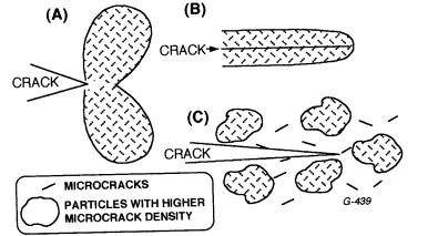
Consider next microcracking, which as noted above can result from and accompany ZrO2 transformation. This can also be an important factor in mechanical properties of monolithic ceramics with thermal expansion anisotropy [as a function of G and E per Eq. (2.4)], and possibly due to EA (Chap. 7, Sec. V.A), with resultant effects on thermal expansion and elastic properties, in addition to other mechanical properties. Ceramic composites with a dispersed phase or phases of differing thermal expansion from the matrix are also a source of microcracks, again per Eq. (2.4) and possible effects of elastic property differences. (Note that in either case, single crystal particles of noncubic structure may have more extreme effects than polycrystalline particles, since the crystalline anisotropy will often accentuate the particle–matrix property differences, especially if the matrix grain size is similar to or > the particle size.) Recall that the original concept of microcracking was for it to occur primarily in two lobes, one located above and one below the crack plane, both mostly somewhat ahead of
Particle (and Grain) Effects |
463 |
the crack tip (Fig. 8.2A). It is now generally accepted that most microcracking occurs as a zone or sheath along the crack surfaces (Fig. 8.2B), i.e. similar to transformation toughening. Thus the effectiveness of this microcracking sheath around the crack surfaces, like the effects of transformation around a crack, are attributed to the strain expansion from microcracking and resultant compressive shielding of the crack tip from some of the tensile stresses driving its propagation. Based on the original modeling, it was predicted that the toughness increases would in turn increase as the distribution of microcrack size narrowed and approached the optimum size for microcracking, but how much impact these size effects have on the crack tip stress shielding has apparently not been addressed. Local concentration of microcracks, i.e. a designed heterogeneity of their spatial distribution by dispersing particles that can produce a higher density of microcracks than the matrix itself, has been proposed (e.g. Fig. 8.2C), which appears to have been demonstrated, as is discussed later.
Consider next crack deflection and branching, the former being one of the earlier nontransforming toughening mechanisms considered, which may be independent of each other and microcracking but can have various interrelations with one another. Modeling showed increased effect over that from increased
FIGURE 8.2 Schematic of microcrack toughening: (A) as originally proposed occurring in two lobes ahead of and above and below the crack, (B) primarily in the crack wake zones as more recently proposed and generally seen as much closer to actual occurrences, and (C) a proposed local concentration of microcracks to enhance their effectiveness by increasing their net concentration while limiting their opportunity for longer range linkage to enhance larger scale crack propagation. Views are normal to the crack plane. (C modified after Rice [13,14], published with permission of Ceramic Engineering and Science Proceedings.)

464 |
Chapter 8 |
fracture area as from crack deflections from a plane path, and effects of the volume fraction of crack deflectors, their spacing and shape on toughening (Fig. 8.3). Certainly one, but not the only, way to obtain crack deflection is to have microcracking occur at and near the crack tip, e.g. similar to a proposed mechanism for intergranular fracture (Fig. 2.3). Another way is to introduce elongated particles, especially platelets with a highly preferred cleavage or preferred fracture surface, e.g. along its larger interfaces with the matrix.
A related, e.g. possibly more extreme, case of crack deflection is the line tension concept for toughening from crack pinning. This assumes that there are particles or other barriers to crack propagation that result in at least temporary pinning of the crack front at these points. Such pinning effects are commonly treated via line tension along the crack front, which, while raising some theoretical issues, has been used to yield quantitative relations for increases in fracture energy for idealized systems (Fig. 8.4A) [20,21]. Simple
FIGURE 8.3 Summary plot of modeling results for increased fracture energy as a function of volume fraction of crack deflecting particles and their shape. Note progressively greater effects of rods (which increases with their aspect ratio, ) versus spherical and platelet (discs), and increased effects of optimized distribution of spherical particles indicating possible benefits of this for rod and disc particles. (From Refs. 23,24,14. Published with permission of Ceramic Engineering and Science Proceedings.)

Particle (and Grain) Effects |
465 |
FIGURE 8.4 Schematic of (A) the basic line tension (T) model and increased fracture energy (γ), after Lange [20], and (B) diminished effects as the crack size approaches the pinning point separation. (After Rice [13], published with permission of Ceramic Engineering and Science Proceedings.)
FIGURE 8.5 Schematic of the crack pinning in a fiber composite as a mechanism to aid fiber pullout. The side view (A) normal to the crack plane shows the crack held up at a fiber, while the top view 1 (B) (i.e. parallel with the crack plane) shows the crack pinned by three fibers in a row and top view 2 (C) shows the crack having advanced beyond the pinned fibers, leaving them with peripheral cracks that most likely enhance fiber pullout. (From Ref. 13. Published with permission of Ceramic Engineering and Science Proceedings.)
modification of this model indicates possible diminishing effects as crack sizes decrease to approach the pinning point spacing (Fig. 8.4B) [13]. Such modeling has also been extended to address anisotropy of shape of the pinning particles, but issues and limitations of resultant anisotropy appear not to have been fully evaluated [13,21]. Similar effects may occur with fiber composites (Fig. 8.5).

466 |
Chapter 8 |
Crack branching, i.e. simply forming of one or more branch cracks along a crack front (Fig. 8.6), while clearly a possible source of increased toughness, has received little or no explicit modeling consideration. This appears to be due, at least in part, to the mistaken view that this is simply an extension of crack deflection. However, this view must be incorrect, since each branch may (and commonly does) have crack deflections. Thus while crack deflection may cause or be a factor in crack branching, and clearly complicates the quantatative evaluation of effects of branching, branching clearly results in energy dissipation and crack stress effects beyond those of a single crack alone with deflections. While crack branching may occur from natural crack bifurcations, it may also arise from crack deflections, whether or not they arise from microcracking, which may also lead directly to branching.
Crack wake bridging has become a widely cited mechanism of toughening in ceramic composites, as it has for monolithic ceramic bodies, based on ready observation of particles bridging the wake zone of cracks in composites (Fig. 8.7) or grains in monolithic ceramics. However, all the issues discussed in Chapter 2 regarding the implications of such observations with larger cracks propagated at limited velocities and then arrested for observations at the intersection of the large cracks with typically machined surfaces and their applicability to normally much smaller flaws controlling ceramic strengths apply here, as will be shown later. Again, the same uncertainties in the details of bridge formation apply, i.e. the extent to which some microcracking or crack branching initiation may occur at, just ahead of, or behind the crack tip to create bridging particle (grains) is also pertinent.
The last toughening mechanism of pullout is well recognized and established as the major mechanism in toughening of continuous fiber ceramic composites, which has been extensively analyzed [19], and whose validity is
FIGURE 8.6 Schematic of crack branching in a view normal to the mean crack plane. Note that branching may occur naturally, e.g. due to differing orientations of preferred fracture planes at different positions along the crack front, due to other sources of crack deflections, or to microcracking, and can coexist with crack deflections and microcracking over and above that which may cause the crack branching.
Particle (and Grain) Effects |
467 |
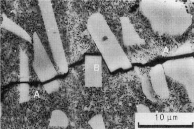
FIGURE 8.7 Fracture and bridging in the wake of a crack in a composite of SiC platelets in an SiC matrix. (A) refers to fractured platelets and (B) to bridging platelets. (From Ref 25. Published with permission of the Journal of Materials Science.)
clearly demonstrated by the effectiveness of fiber coatings to inhibit fiber–matrix bonding and hence enhance fiber pullout [26]. Besides such various direct observations of fiber pullout, pullout is also consistent with the larger scale of generally noncatastrophic propagating cracks (that may frequently be partly or fully arrested) in such fiber composites. However, its validity and applicability to progressively chopped (i.e. short) fiber, to whisker and platelet, and ultimately to normal particulate composites is progressively more uncertain. This arises in part due to the scales of possible pullout being so much less in such composites compared to continuous fiber composites, making the former difficult to distinguish clearly from the simple equivalent of intergranular fracture in such composites. Added uncertainties arise since in these other composites, pullout becomes similar to if not identical to crack bridging with all of its uncertainties.
Though often not emphasized or even explicitly identified, it is important to note the known or probable dependences of the various toughening mechanisms on microstructural parameters such as particle (grain) size, uniformity, orientation, and (where applicable) fracture mode. It is also important to address similarly known or possible effects of crack size. Both are summarized in Table 8.1, based in part on an earlier evaluation of Rice [15].

TABLE 8.1 Summary of Status and Microstructural and Crack Size Dependence of Toughening Mechanisms
Toughening |
Verifi- |
|
|
mechanism |
cation |
Particle (grain) size dependence |
Crack size effect |
|
|
|
|
Transfor- |
Substan- |
Increased optimum size with increased stabilization |
Some R-curve effects shown |
mation |
tial |
and matrix E, and possibly decreasing volume fraction. |
|
|
|
Decreasing benefits as size distribution broadens |
|
Micro- |
Some |
Optimum size, e.g. per Eq. (2.4), probable minimum |
Possible increased |
cracking |
|
size and increasing degradation at larger sizes. |
effectiveness as crack size |
|
|
Decreasing benefits as size distribution broadens |
increases |
Crack |
Some |
No clear direct size effect, but possibly some via |
Probably increased effects, |
deflection |
|
spacing effects for a given volume fraction. Significant |
then saturation as crack size |
|
|
orientation effect. Size distribution effects uncertain |
increases |
Crack |
Limited |
Increases with decreasing particle size, but probable |
Reduced effects at finer, then |
pinning |
|
limitations at small and large sizes. Probable |
saturated at larger, sizes |
|
|
significant orientation and size distribution effects |
|
Crack |
Limited |
Probably depends on size and orientation, but in |
Probably greater effect and |
branching |
|
varying fashions as a function of possible contributing |
occurrence with increasing |
|
|
mechanism(s), e.g. crack deflection or microcracking |
crack size |
Crack |
Some |
Generally increases as particle size increases. More |
Increased effect, then |
bridging |
|
effective for intergranular versus transgranular |
saturation, as crack size |
|
|
fracture |
increases |
Pullout |
High |
Based on area dependence of frictional work in |
Not for finer fibers, but |
(especially |
|
pullout, linearly increased effects with the inverse of |
maybe for large fibers |
of fibers) |
|
fiber diameter. Significant orientation dependence |
(filaments), and for whiskers |
|
|
|
and platelets |
|
|
|
|
468
8 Chapter
Particle (and Grain) Effects |
469 |
The first of two other important issues that are often not addressed is that of the extent to which cracks actually interact with the dispersed particles. This is generally not an issue in most fiber (and related directional solidified) composites, since the issue of fiber–crack orientations and opportunities for cracks avoiding the fibers is generally effectively zero. Such opportunity is also limited in composites of high-volume fractions of dispersed particles, whiskers, and platelets but is dependent on orientation effects in the order listed. However, as the volume fractions decrease, particularly for more equiaxed particulates, the degree of crack–particle interaction may decrease faster than expected. This may arise since while it is inviting to use straight lines on a photomicrograph to estimate the extent of crack–particle interactions, this may be very misleading, Thus as previously shown by Rice [13], limited curvature of cracks may allow them to avoid many particles, as is illustrated in Fig. 8.8. Further, the degree of crack–particle interaction can be dependent on crack velocity, a factor almost universally neglected, but limited study clearly shows a significant velocity dependence, as is discussed later.
The issue of possible crack–particle interaction has been addressed in some models as outlined in Fig. 8.9. This indicates that there is some but less interaction between a crack and a particle in hydrostatic tension, e.g. due to its having a thermal expansion greater than, and good bonding to, the matrix. On the other hand, the nature of the stress in the surrounding matrix for particles with lower thermal expansion than the matrix indicates stronger crack–particle interactions. However, such models neglect the changes in the local matrix stress states as the crack approaches the particle, as well as possible effects of crack velocity (which can vary the stresses ahead of the crack tip).
The second commonly neglected issue in most models (and many studies) is that of variations of the spatial distribution of the dispersed phase, especially serious heterogeneities of it. Thus an agglomerate or other accumulation of the matrix material often acts as a weaker source for easier local crack propagation, and particularly seriously, if large enough, as a source of failure. Equally, and often more seriously, is when there is a clustering or agglomeration of the dispersed particulate material, since this often can act as a defect, e.g. a flaw, and one which is often then surrounded by a region of reduced toughness due to its frequent lower concentration in the area surrounding the agglomeration (Fig. 8.10).
The above models have implications for crack propagation behavior beyond the measurement of fracture toughness, but they leave various uncertainties, some of which have been noted above. Another uncertainty is environmental effects, i.e. SCG. While the models provide some guidance of how SCG may progress, they by themselves provide no guidance as to the occurrence of SCG, which probably entails issues of the contiguity of dispersed particles or grain boundary phases subject to SCG, e.g. as noted for Si3N4 made with oxide additives (Chap. 2, Sec. III.B).