

PS-2020a / part17
.pdfDICOM PS3.17 2020a - Explanatory Information |
Page 831 |
FFFF Advanced Blending Presentation State
Storage Encoding Example (Informative)
This section illustrates the usage of the Advanced Blending Presentation State for a functional MRI study.
FFFF.1 Introduction
Quantitative imaging provides measurements of physical properties, in vivo and non-invasively, for research and clinical practice. DICOM support for parametric maps provides a structure for organizing these results as an extension of the already widely-used imaging standard. The addition of color LUT support for parametric maps bridges the gap between data handling and visualization.
AnexampleofquantitativeimaginginclinicalpracticetodayistheuseofMRI,PETandothermodalitiesinbrainmappingfordiagnostic assessment in pre-treatment planning for tumor, epilepsy, arterio-venous malformations (AVMs) and other conditions. MR Diffusion tensor imaging (DTI) results in fractional anisotropy (FA) and other parametric maps highlighting white matter structures. Task-based functional MRI (fMRI) highlights specific areas of eloquent cortex (gray matter) as expressed in statistical activation maps. Other parameters and modalities including perfusion, MR spectroscopy, and PET are often employed to locate and characterize lesions by means of their hyperand hypo-metabolism and -perfusion in parametric maps.
The visualization of multiple parametric maps and sources of anatomical information in the same space requires the tools to highlight areas of interest (and hide irrelevant areas) in parametric maps. Two important tools provided in this supplement are thresholding of parametric maps by their real-world values, and blending of multiple images in a single view.
In this example the series 2 to 5 have a lower resolution and are expected to be resampled to have the same resolution as series 1 as this is identified as series to be used for target Geometry.
FFFF.2 Example
The example describes the blending of five series:
Series 1: the anatomical series which is stored as a single volume in an Enhanced MR Image object having no Color LUT attached. The Image will be displayed with a Relative Opacity of 0.7.
Figure FFFF.2-1. Anatomical image
Series 2: the DTI series which is stored as an Enhanced MR Color Image object means that no RGB transformation is needed. The Image will be displayed with a Relative Opacity of 1 - 0.7.
- Standard -
Page 832 |
DICOM PS3.17 2020a - Explanatory Information |
Figure FFFF.2-2. DTI image
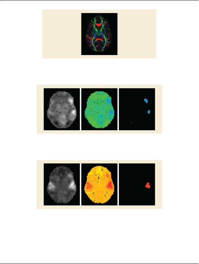
Series 3: Reading task captured in a Parametric Map with Color LUT Winter attached to it. The Image will be displayed with threshold range 6% to 50%. Opacity will be equal divided with the other two task maps.
Figure FFFF.2-3. Reading task image with coloring and threshold applied
Series 4: Listening task captured in a Parametric Map with Color LUT Fall attached to it. The Image will be displayed with threshold range 9% to 60%. Opacity will be equal divided with the other two task maps.
Figure FFFF.2-4. Listening task image with coloring and threshold applied
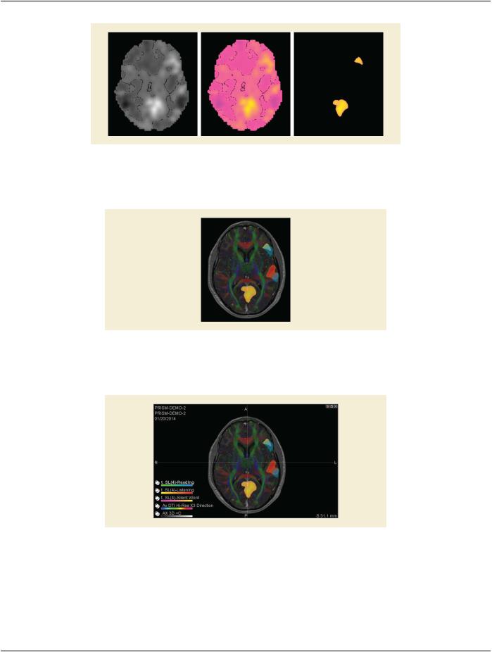
Series 5: Silent word generation task captured in a Parametric Map with Color LUT Spring attached to it. The Image will be displayed with threshold range 7% to 75%. Opacity will be equal divided with the other two task maps.
- Standard -
DICOM PS3.17 2020a - Explanatory Information |
Page 833 |
Figure FFFF.2-5. Silent word generation task image with coloring and threshold applied
The result of the first blending operation (FOREGROUND) will be blended with the result of the second blending operation (EQUAL) through a FOREGROUND blending operation with a Relative Opacity of 0.6.
Figure FFFF.2-6. Blended result
Figure FFFF.2-6 shows the final result with information of patient and different blended image layers. The overlay of the patient and layer information is not described in the object but would be application specific behavior.
Figure FFFF.2-7. Blended result with Patient and Series information
- Standard -

Page 834 DICOM PS3.17 2020a - Explanatory Information
FFFF.3 Encoding Example
Table FFFF.3-1. Encoding Example
Nesting |
Attribute Name |
Tag |
Value |
Comment |
|
Advanced Blending Sequence |
(0070,1B01) |
|
|
|
%item 1 |
|
|
Identifies Anatomical |
|
|
|
|
Series, no subset of series |
|
|
|
|
or registration |
> |
Blending Input Number |
(0070,1B02) |
1 |
|
> |
Study Instance UID |
(0020,000D) |
"1.3.46.670589.11.3" |
|
> |
Series Instance UID |
(0020,000E) |
"1.3.46.670589.11.3.45" |
|
> |
Geometry for Display |
(0070,1B08) |
TRUE |
Series geometry shall be |
|
|
|
|
usedastargetgeometryfor |
|
|
|
|
the blending operation |
|
%enditem 1 |
|
|
|
|
%item 2 |
|
|
Identifies DTI Series, no |
|
|
|
|
subset of series is used, no |
|
|
|
|
registration present |
> |
Blending Input Number |
(0070,1B02) |
2 |
|
> |
Study Instance UID |
(0020,000D) |
"1.3.46.670589.11.3" |
|
> |
Series Instance UID |
(0020,000E) |
"1.3.46.670589.11.3.49" |
|
> |
Geometry for Display |
(0070,1B08) |
FALSE |
Series geometry shall not |
|
|
|
|
beusedastargetgeometry |
|
|
|
|
for the blending operation |
|
%enditem 2 |
|
|
|
|
%item 3 |
|
|
Identifies first Parametric |
|
|
|
|
map, no registration |
> |
Blending Input Number |
(0070,1B02) |
3 |
|
> |
Study Instance UID |
(0020,000D) |
"1.3.46.670589.11.3" |
|
> |
Series Instance UID |
(0020,000E) |
"1.3.46.670589.11.3.56" |
|
> |
Threshold Sequence |
(0070,1B11) |
|
|
> |
%item 3-1 |
|
|
|
>> |
Threshold Value Sequence |
(0070,1B12) |
|
|
>> |
%item 3-1-1 |
|
|
|
>>> |
Threshold Value |
(0070,1B14) |
6 |
First threshold value |
>> |
%enditem 3-1-1 |
|
|
|
>> |
%item 3-1-2 |
|
|
|
>>> |
Threshold Value |
(0070,1B14) |
50 |
Second threshold value |
>> |
%enditem 3-1-2 |
|
|
|
>> |
Threshold Type |
(0070,1B13) |
RANGE_INCL |
|
> |
%enditem 3-1 |
|
|
|
|
%enditem 3 |
|
|
|
|
%item 4 |
|
|
Identifies second |
|
|
|
|
Parametric map, no |
|
|
|
|
registration |
> |
Blending Input Number |
(0070,1B02) |
3 |
|
- Standard -

|
DICOM PS3.17 2020a - Explanatory Information |
Page 835 |
||
Nesting |
Attribute Name |
Tag |
Value |
Comment |
> |
Study Instance UID |
(0020,000D) |
"1.3.46.670589.11.3" |
|
> |
Series Instance UID |
(0020,000E) |
"1.3.46.670589.11.3.58" |
|
> |
Threshold Sequence |
(0070,1B11) |
|
|
> |
%item 4-1 |
|
|
|
>> |
Threshold Value Sequence |
(0070,1B12) |
|
|
>>> |
%item 4-1-1 |
|
|
|
>>> |
Threshold Value |
(0070,1B14) |
9 |
First threshold value |
>> |
%enditem 4-1-1 |
|
|
|
>> |
%item 4-1-2 |
|
|
|
>>> |
Threshold Value |
(0070,1B14) |
60 |
Second threshold value |
>> |
%enditem 4-1-2 |
|
|
|
>> |
Threshold Type |
(0070,1B13) |
RANGE_INCL |
|
> |
%enditem 4-1 |
|
|
|
|
%enditem 4 |
|
|
|
|
%item 5 |
|
|
Identifies third Parametric |
|
|
|
|
map, no registration |
> |
Blending Input Number |
(0070,1B02) |
3 |
|
> |
Study Instance UID |
(0020,000D) |
"1.3.46.670589.11.3" |
|
> |
Series Instance UID |
(0020,000E) |
"1.3.46.670589.11.3.59" |
|
> |
Threshold Sequence |
(0070,1B11) |
|
|
> |
%item 5-1 |
|
|
|
>> |
Threshold Value Sequence |
(0070,1B12) |
|
|
>> |
%item 5-1-1 |
|
|
|
>>> |
Threshold Value |
(0070,1B14) |
7 |
First threshold value |
>> |
%enditem 5-1-1 |
|
|
|
>> |
%item 5-1-2 |
|
|
|
>>> |
Threshold Value |
(0070,1B14) |
75 |
Second threshold value |
>> |
%enditem 5-1-2 |
|
|
|
>> |
Threshold Type |
(0070,1B13) |
RANGE_INCL |
|
> |
%enditem 5-1 |
|
|
|
|
%enditem 5 |
|
|
|
|
Pixel Presentation |
(0008,9205) |
"TRUE_COLOR" |
|
|
Blending Display Sequence |
(0070,1B04) |
|
|
|
%item 1 |
|
|
|
> |
Blending Display Input Sequence |
(0070,1B03) |
|
|
> |
%item 1-1 |
|
|
Anatomical series, no |
|
|
|
|
threshold |
>> |
Blending Input Number |
(0070,1B02) |
1 |
|
> |
%enditem 1-1 |
|
|
|
> |
%item 1-2 |
|
|
DTI series, no threshold |
>> |
Blending Input Number |
(0070,1B02) |
2 |
|
> |
%enditem 1-2 |
|
|
|
- Standard -

Page 836 |
DICOM PS3.17 2020a - Explanatory Information |
|
||
Nesting |
Attribute Name |
Tag |
Value |
Comment |
> |
Relative Opacity |
(0070,0403) |
0.7 |
|
> |
Blending Mode |
(0070,1B06) |
FOREGROUND |
|
> |
Blending Input Number |
(0070,1B02) |
6 |
Output is used for later |
|
|
|
|
Blending |
|
%enditem 1 |
|
|
|
|
%item 2 |
|
|
|
> |
Blending Display Input Sequence |
(0070,1B03) |
|
|
> |
%item 2-1 |
|
|
Parametric series 1 |
>> |
Blending Input Number |
(0070,1B02) |
3 |
|
> |
%enditem 2-1 |
|
|
|
> |
%item 2-2 |
|
|
Parametric series 2 |
>> |
Blending Input Number |
(0070,1B02) |
4 |
|
> |
%enditem 2-2 |
|
|
|
> |
%item 2-3 |
|
|
Parametric series 3 |
>> |
Blending Input Number |
(0070,1B02) |
5 |
|
> |
End Sequence Item 2-3 |
|
|
|
> |
Blending Mode |
(0070,1B06) |
EQUAL |
|
> |
Blending Input Number |
(0070,1B02) |
7 |
Output is used for later |
|
|
|
|
Blending |
|
%enditem 2 |
|
|
|
|
%item 3 |
|
|
|
> |
Blending Display Input Sequence |
(0070,1B03) |
|
|
> |
%item 3-1 |
|
|
Output first blending |
|
|
|
|
operation, no threshold |
>> |
Blending Input Number |
(0070,1B02) |
6 |
|
> |
%enditem 3-1 |
|
|
|
> |
%item 3-2 |
|
|
Output second blending |
|
|
|
|
operation, no threshold |
>> |
Blending Input Number |
(0070,1B02) |
7 |
|
> |
%enditem 3-2 |
|
|
|
> |
Relative Opacity |
(0070,0403) |
0.6 |
|
> |
Blending Mode |
(0070,1B06) |
FOREGROUND |
|
|
%enditem 3 |
|
|
No Parametric Blending |
|
|
|
|
Input Number is present as |
|
|
|
|
this step defines the output |
|
|
|
|
to be displayed. |
- Standard -

DICOM PS3.17 2020a - Explanatory Information |
Page 837 |
GGGG Patient Radiation Dose Structured
Report Document (Informative)
This Annex contains examples of the use of Patient Radiation Dose templates within Patient Radiation Dose Structured Report Doc- uments.
GGGG.1 Skin Dose Map Example
The following example shows the report of the skin dose map calculated from the dose delivered during an X-Ray interventional car- diology procedure.
The calculation uses a Radiation Dose SR provided by a Single Plane X-Ray Angiography equipment of the manufacturer "A". The Radiation Dose SR is created during one procedure step, corresponding to the coronary stenting of an adult male of 83 kg and 179 cm height.
The skin dose calculations are performed by an application on a separated workstation of the manufacturer "B", operated by the medical physicist, who is logged into the workstation at the time of the creation of the Patient Radiation Dose Structured Report doc- ument.
The dose calculation application generates a Patient Radiation Dose Structured Report document and a Secondary Capture Image containing an image of the dose distribution over the deployed skin of the patient model.
The dose calculation application uses the following settings and assumptions:
•RDSR Source Data:
•All the Irradiation Event UIDs are used in the calculation of the skin dose map.
•Patient Model:
•The patient model is a combination of two elliptic cylinders to represent the chest and neck of the patient.
•The actual dimensions of the model are determined by the age, gender, height, and weight of the patient.
•In this example the exact height and weight of the patient are used to create the model. The resulting elliptic cylinder for the chest of the model is 31 cm in the AP dimension and 74 cm in the lateral dimension.
•The application creates internally a 3D voxelized model that is stored in a DICOM SOP Instance.
•Patient Model Registration:
•The distance from the top of the patient's head to the head of the table (measured during the procedure) is known. The location of the patient head and table head are stored in a Spatial Fiducials SOP instance.
•The application uses fiducials to register the patient model with the data of the source Radiation Dose SR.
•A-priori knowledge of the distance from the table head to the system Isocenter at table zero position is calibrated offline.
•The table tilt, cradle, and rotation angles are ignored because the description of the acquisition geometry is incomplete in the Radiation Dose SR. Only table translations relative to the Isocenter are considered in the calculations.
•Beam Attenuators:
•A-priori knowledge of the model of the table and mattress (i.e., shape, dimensions, and absorption material) is calibrated offline, anditisreferencedinternallybytheapplication.Themodelcontainsthesamecoordinatesystemastheoneusedintheequipment referenced in the Radiation Dose SR, so there is no need of another registration SOP instance.
•The X-Ray filter information from the source Radiation Dose SR is used by the application. There is no other a-priori knowledge of the X-Ray filtration.
- Standard -

Page 838 DICOM PS3.17 2020a - Explanatory Information
Table GGGG.1-1. Skin Dose Map Example
Node |
Code Meaning of Concept Name |
Code or Example Value |
Comment |
1 |
Patient Radiation Dose Report |
|
TID 10030 |
1.1 |
Language of Content Item and |
(En, IETF4646, "English") |
TID 1204 |
|
Descendants |
|
|
1.2 |
Observer Type |
(121007, DCM, "Device") |
TID 1002 |
1.3 |
Device Observer UID |
1.2.3.4.566.1.5 |
TID 1004 |
1.4 |
Device Observer Name |
MedPhys-01 |
TID 1004 |
1.5 |
Device Observer Manufacturer |
Manufacturer B |
TID 1004 |
1.6 |
Device Observer Model Name |
Dose Workstation v1 |
TID 1004 |
1.7 |
Observer Type |
(121006, DCM, "Person") |
TID 1002 |
1.8 |
Person Observer Name |
Doe^John^^Dr^PhD |
TID 1003 |
1.9 |
Person Observer's Role in the |
(C1708969, UMLS, "Medical |
TID 1003 |
|
Organization |
Physicist") |
|
1.10 |
Radiation Dose Estimate |
|
TID 10031 |
1.10.1 |
Radiation Dose Estimate Name |
Skin Dose Map |
TID 10031 |
1.10.2 |
Comment |
Single Plane XA |
TID 10031 |
1.10.3 |
Radiation Dose Estimate Methodology |
|
TID 10033 |
1.10.3.1 |
SR Instance Used |
|
Radiation Dose SR #1 |
1.10.3.1.1 |
SOP Class UID |
1.2.840.1008.5.1.4.1.1.88.67 |
|
1.10.3.1.2 |
SOP Instance UID |
1.2.3.4.566.77.1 |
|
1.10.3.1.3 |
Spatial Fiducials |
|
Spatial Fiducials |
1.10.3.1.3.1 |
SOP Class UID |
1.2.840. 1008.5.1.4.1.1.66.2 |
|
1.10.3.1.3.2 |
SOP Instance UID |
1.2.3.4.44.222.33.1 |
|
1.10.3.2 |
Patient Radiation Dose Model |
|
TID 10033 |
1.10.3.2.1 |
Patient Model Type |
(128418, DCM, "Simple Object |
TID 10033 |
|
|
Model") |
|
1.10.3.2.2 |
Radiation Transport Model Type |
(128422,DCM,"VoxelizedRadiationTID 10033 |
|
|
|
Transport Model") |
|
1.10.3.2.3 |
Patient Radiation Dose Model Data |
|
Parametric map |
1.10.3.1.3.1 |
SOP Class UID |
1.2.840.1008.5.1.4.1.1.30 |
|
1.10.3.1.3.2 |
SOP Instance UID |
1.2.3.43.44.55.1 |
|
1.10.3.2.4 |
Patient Radiation Dose Model ReferenceDOI:1.2.3.4 |
TID 10033 |
|
1.10.3.2.5 |
Comment |
Combined Elliptic Cylinders |
TID 10033 |
1.10.3.2.6 |
Patient Model Demographics |
|
TID 10033 |
1.10.3.2.6.1 |
Model Minimum Age |
18 (a, UCUM, "year") |
TID 10033 |
1.10.3.2.6.2 |
Model Maximum Age |
90 (a, UCUM, "year") |
TID 10033 |
1.10.3.2.6.3 |
Model Patient Sex |
(M, DCM, "Male") |
TID 10033 |
1.10.3.2.6.4 |
Model Minimum Weight |
83 (kg, UCUM, "kilogram") |
TID 10033 |
1.10.3.2.6.5 |
Model Maximum Weight |
83 (kg, UCUM, "kilogram") |
TID 10033 |
1.10.3.2.6.6 |
Model Minimum Height |
179 (cm, UCUM, "Centimeter") |
TID 10033 |
1.10.3.2.6.7 |
Model Maximum Height |
179 (cm, UCUM, "Centimeter") |
TID 10033 |
1.10.3.2.7 |
Patient Model Registration |
|
TID 10033 |
- Standard -

|
DICOM PS3.17 2020a - Explanatory Information |
Page 839 |
|
Node |
Code Meaning of Concept Name |
Code or Example Value |
Comment |
1.10.3.2.7.1 |
Comment |
Distance from the top of patient's |
TID 10033 |
|
|
headtotheheadofthetable=10cm |
|
1.10.3.2.7.2 |
Registration Method |
(125022,DCM,"FiducialAlignment")TID 10033 |
|
1.10.3.2.7.3 |
Spatial Registration |
|
Spatial Registration |
1.10.3.1.3.1 |
SOP Class UID |
1.2.840. 1008.5.1.4.1.1.66.1 |
|
1.10.3.1.3.2 |
SOP Instance UID |
1.2.3.4.44.3.2.11 |
|
1.10.3.3 |
X-Ray Beam Attenuator |
|
TID 10033 |
1.10.3.3.1 |
Attenuator Category |
(128459, DCM, "Table") |
TID 10033 |
1.10.3.3.2 |
Equivalent Attenuator Material |
(256501007, SCT, "Carbon fiber") TID 10033 |
|
1.10.3.3.3 |
Equivalent Attenuator Thickness |
100 (mm, UCUM, "Millimeter") |
TID 10033 |
1.10.3.3.4 |
Attenuator Description |
X-Ray Table with Mattress |
TID 10033 |
1.10.3.3.5 |
X-Ray Beam Attenuator Model |
|
TID 10033 |
1.10.3.3.5.1 |
Radiation Transport Model Type |
(128421,DCM,"GeometricRadiationTID 10033 |
|
|
|
Transport Model") |
|
1.10.3.3.5.2 |
X-RayBeamAttenuatorModelReferenceDOI:1.4.2.3 |
TID 10033 |
|
1.10.3.4 |
Radiation Dose Estimate Method |
|
TID 10033 |
1.10.3.4.1 |
Radiation Dose Estimate Method Type (128480, DCM, "Analytical |
TID 10033 |
|
|
|
Algorithm") |
|
1.10.3.4.2 |
Radiation Dose Estimate Parameters |
|
TID 10034 |
1.10.3.4.2.1 |
(128433, DCM, "Tissue Air Ratio") |
1.06 ({ratio}, UCUM, "ratio") |
TID 10034 |
1.10.3.4.2.1.1 |
RadiationDoseEstimateParameterType(C70774, NCIt, "Unit Conversion |
TID 10034 |
|
|
|
Factor") |
|
1.10.3.4.2.2 |
(128408, DCM, "Patient AP Dimension")31 (cm, UCUM, "Centimeter") |
TID 10034 |
|
1.10.3.4.2.2.1 |
RadiationDoseEstimateParameterType(121206, DCM, "Distance") |
TID 10034 |
|
1.10.3.4.2.3 |
(128409, DCM, "Patient Lateral |
74 (cm, UCUM, "Centimeter") |
TID 10034 |
|
Dimension") |
|
|
1.10.3.4.2.3.1 |
RadiationDoseEstimateParameterType(121206, DCM, "Distance") |
TID 10034 |
|
1.10.3.4.2.4 |
(MyCode001, 99MyScheme, "Linear |
0.010536(/cm,UCUM,"/Centimeter")TID 10034 |
|
|
attenuation coefficient of the table and |
|
|
|
mattress") |
|
|
1.10.3.4.3 |
Radiation Dose Estimate Method |
DOI:4.2.13.4 |
TID 10033 |
|
Reference |
|
|
1.10.4 |
Radiation Dose Estimate Representation |
TID 10032 |
|
1.10.4.1 |
Distribution Representation |
(128485, DCM, "Skin Dose Map") |
TID 10032 |
1.10.4.2 |
Radiation Dose Representation Data |
|
TID 10032 |
1.10.4.2.1 |
SOP Class UID |
1.2.840.10008.5.1.4.1.1.7 |
Secondary Capture |
1.10.4.2.2 |
SOP Instance UID |
1.2.3.1.2.3.3 |
|
1.10.4.3 |
Organ |
(181469002, SCT, "Skin") |
TID 10032 |
1.10.4.4 |
Comment |
2D map of the dose on the deployedTID 10032 |
|
|
|
skin |
|
1.10.5 |
Organ Radiation Dose Information |
|
TID 10031 |
1.10.5.1 |
Organ |
(181469002, SCT, "Skin") |
TID 10031 |
1.10.5.2 |
Comment |
Skin in the area of the chest and |
TID 10031 |
|
|
neck |
|
- Standard -

Page 840 |
DICOM PS3.17 2020a - Explanatory Information |
|
|
Node |
Code Meaning of Concept Name |
Code or Example Value |
Comment |
1.10.5.3 |
(DCM, 128531, "Maximum Absorbed |
3000 (mGy, UCUM, "mGy") |
TID 10031 |
|
Radiation Dose") |
|
|
1.10.5.3.1 |
(371884006, SCT, "+/-, range of |
750 (mGy, UCUM, "mGy") |
TID 10031 |
|
measurement uncertainty") |
|
|
1.11 |
Comment |
Skin Dose Map Report |
TID 10030 |
GGGG.2 Dual-source CT Organ Radiation Dose Example
The following example shows the report of the organ dose calculated for a dual-source CT scan.
The calculation uses a Radiation Dose SR provided by a CT system that has dual X-Ray tubes. The Radiation Dose SR is created during the acquisition of Neck DE_CAROTID CT scan of an adult male of 75 kg and 165 cm height.
ThedosecalculationsareperformedontheCTsystem.ThedosecalculationapplicationgeneratesaPatientRadiationDoseStructured Report document and a Dose Point Cloud containing an image of the dose distribution for the patient model.
The dose calculation application uses the following settings and assumptions:
•RDSR Source Data:
•The Irradiation Events associated with the CT Localizer Radiograph are excluded.
•The Irradiation Event UID from the helical CT series is used in the calculation of the organ dose.
•Patient Model:
•The patient model is a stylized anthropomorphic model of the patient.
•Organs are represented by simple geometric shapes described by mathematical equations. The parameters of the equations describing the location, shape, and dimension of the organs are stored in a DICOM SOP Instance.
•In this example the gender and age of the patient are used to select the appropriate phantom from the existing phantom library.
•Patient Model Registration:
•Image Content-based Alignment between the CT images Frame of Reference and the 3D stylized model Frame of Reference is used for registration.
•Beam Attenuators:
•Additional Aluminum filtration is used in the methodology and the equivalent HVL for the scanner model used in the method is given.
Table GGGG.2-1. Dual-source CT Organ Radiation Dose Example
Node |
Code Meaning of Concept Name |
Code or Example Value |
Comment |
1 |
Patient Radiation Dose Report |
|
TID 10030 |
1.1 |
Language of Content Item and |
(En, IETF4646, "English") |
TID 1204 |
|
Descendants |
|
|
1.1.1 |
Country of Language |
(CA, ISO3166_1, "Canada") |
TID 1204 |
1.2 |
Observer Type |
(121007, DCM, "Device") |
TID 1002 |
1.3 |
Device Observer UID |
2.13.4.5.2.33.5 |
TID 1004 |
1.4 |
Device Observer Name |
RUMC-213 |
TID 1004 |
1.5 |
Device Observer Manufacturer |
Manufacturer DEX |
TID 1004 |
1.6 |
Device Observer Model Name |
Scanner 4500 |
TID 1004 |
- Standard -