

5.1.2.Supercapacitor design
The supercapacitor is a new energy storage technology similar to the conventional capacitors and therefore governed by the same fundamental equations as capacitors, but utilize higher surface area electrodes and thinner dielectrics to achieve greater capacitances. This allows to reach energy densities greater than those of conventional capacitors and power densities greater than those of batteries. As a result, supercapacitors may become an attractive power solution for an increasing number of short term high power density applications such as load leveling and regenerative braking ESS.
Supercapacitors, also known as ultracapacitors, electrochemical double-layer capacitors (EDLC) or electrochemical capacitors, utilize high surface area electrode materials and thin electrolytic dielectrics to achieve capacitances several orders of magnitude larger than conventional capacitors [8,9]. In doing so, supercapacitors are able to attain greater energy
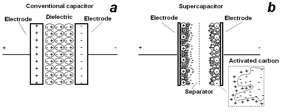
Fig. 1. Comparison of capacitor and supercapacitor design
densities while still maintaining the characteristic high power density of conventional capacitors.
Conventional capacitors consist of two conducting electrodes separated by an insulating dielectric material. When a voltage is applied to a capacitor, opposite charges accumulate on the surfaces of each electrode. The charges are kept separate by the dielectric, thus producing an electric field that allows the capacitor to store energy (Fig. 1.a). Capacitance C is defined as the ratio of stored (positive) charge Q to the applied voltage V:
![]() ,
(1)
,
(1)
For a conventional capacitor, C is directly proportional to the surface area A of each electrode and inversely proportional to the distance D between the electrodes:
![]() , (2)
, (2)
The product of the first two factors on the right
hand side of the last equation is a constant of proportionality
wherein
![]() is
the
is
the
![]() dielectric
constant (or “permittivity”) of free space and
is the dielectric constant of the insulating material between the
electrodes. The two primary attributes of a capacitor are its energy
density and power density. For either measure, the density can be
calculated as a quantity per unit mass or per unit volume. The energy
E stored in a capacitor is directly proportional to its capacitance:
dielectric
constant (or “permittivity”) of free space and
is the dielectric constant of the insulating material between the
electrodes. The two primary attributes of a capacitor are its energy
density and power density. For either measure, the density can be
calculated as a quantity per unit mass or per unit volume. The energy
E stored in a capacitor is directly proportional to its capacitance:
![]() .
(3)
.
(3)
In general, the power P is the energy expended per unit time. To determine P for a capacitor, though, one must consider that capacitors are generally represented as a circuit in series with an external “load” resistance R. The internal components of the capacitor (e.g., current collectors, electrodes, and dielectric material) also contribute to the resistance, which is measured in aggregate by a quantity known as the equivalent series resistance (ESR). The voltage during discharge is determined by these resistances. When measured at matched impedance (R = ESR), the maximum power Pmax for a capacitor is given by:
![]() .
(4)
.
(4)
This relationship shows how the ESR can limit the maximum power of a capacitor [10]. Conventional capacitors have relatively high power densities, but relatively low energy densities when compared to electrochemical batteries and to fuel cells. That is, a battery can store more total energy than a capacitor, but it cannot deliver it very quickly, which means its power density is low. Capacitors, on the other hand, store relatively less energy per unit mass or volume, but what electrical energy they do store can be discharged rapidly to produce a lot of power, so their power density is usually high. Supercapacitors are governed by the same basic principles as conventional capacitors. However, they incorporate electrodes with much higher surface areas A and much thinner dielectrics that decrease the distance D between the electrodes. Thus, from (2) this leads to an increase in both capacitance and energy. Furthermore, by maintaining the low ESR characteristic of conventional capacitors, supercapacitors also are able to achieve comparable power densities. Additionally, supercapacitors have several advantages over electrochemical batteries and fuel cells, including higher power density, shorter charging times, and longer cycle life and shelf life. Electrochemical double-layer capacitors (EDLCs) are constructed from two carbon-based electrodes, an electrolyte, and a separator. Fig.1.b. provides a schematic of a typical EDLC. Like conventional capacitors, EDLCs store charge electrostatically, or non-Faradaically, and there is no transfer of charge between electrode and electrolyte. EDLCs utilize an electrochemical double-layer of charge to store energy. As voltage is applied, charge accumulates on the electrode surfaces. Following the natural attraction of unlike charges, ions in the electrolyte solution diffuse across the separator into the pores of the electrode of opposite charge. However, the electrodes are engineered to prevent the recombination of the ions. Thus, a double-layer of charge is produced at each electrode. These double-layers, coupled with an increase in surface area and a decrease in the distance between electrodes, allow EDLCs to achieve higher energy densities than conventional capacitors. Because there is no transfer of charge between electrolyte and electrode, there are no chemical or composition changes associated with non-Faradaic processes. For this reason, charge storage in EDLCs is highly reversible, which allows them to achieve very high cycling stabilities. The performance characteristics of an EDLC can be adjusted by changing the nature of its electrolyte. While the nature of the electrolyte is of great importance in supercapacitor design, the subclasses of EDLCs are distinguished primarily by the form of carbon they use as an electrode material. Carbon electrode materials generally have higher surface area, lower cost, and more established fabrication techniques than other materials, such as conducting polymers and metal oxides. Different forms of carbon materials that can be used to store charge in EDLC electrodes are activated carbons, carbon aerogels, and carbon nanotubes.
The typical maximum capacity of popular supercapacitors produced by Maxwell company is 3000F at 2.7V for single capacitor and 63F for 125V module. While the supercapacitor specific energy density is 5 Wh/kg, significantly lower than modern Lithium-Ion batteries 80…150 Wh/kg and flywheels 100 Wh/kg, the specific power density 10000 W/kg is strongly higher than Li-Ion accumulator and flywheels specific power 500…2000 W/kg and 1000 W/kg respectively. The combination of outstanding power characteristics with poor energy capacity does not allow to the supercapacitor to totally replace the accumulator batteries. Also supercapacitor high self-discharge ratio 14% per month in comparison to accumulator self discharge 2…5% per month embarrases the utilising of supercapacitors as long term energy storage. By merging a supercapacitor and a battery together in a hybrid ESS it will be possible for supercapacitors to replace the conventional battery. Supercapacitors need batteries to store the energy and are basically used as a leveling or peak shaving buffer between the battery and the consumer. In comparison with the supercapacitor lifetime of 106 charge-discharge cycles which is comparable to flywheels 107 cycles life, the lifetime of an accumulator is usually limited by 300-3000 cycles, which makes the accumulator battery unfitted for often repeating charge–discharge modes at a typical 30-60s stop-to-stop vehicle run. Supercapacitors can be charged and discharged up to 106 times instead the batteries, that coould witdhstand 102…103 cycles. The typical lifetime of supercapacitor should be 10…12 years instead of accumulator battery 3…7 years depending on type – lower value for the valve regulated lead-acid batteries, higher – for Li-Ion batteries. The advantage of supercapacitors versus accumulators is possibility quick charge measured in seconds with current comparable to discharge current. Accumulator charge current is 0.1C, where C – accumulator capacity in Ah, therefore traction power peak shaving only from battery is not efficient due to impossibility to charge such a battery fast enough neither from a power supply network nor using regenerative braking circuit. Power peak shaving from battery can cause full discharge, while battery recharging would take up to 1.5-10 h, the battery is unusable for traction purposes. The supercapacitor ESS fast discharge feature prevents accumulator from frequently short term discharge with high load current, which increases the accumulator battery lifetime. For preventing of uncontollable high current and power flows supercapacitor direct connection in power scheme without converter [11,12] may not be widely used for high power applicatons due to the low ESR values.