
- •Energy Saving Technologies Riga Technical University
- •Content
- •Introduction 10
- •1. Energy Saving Technologies in generation, conversion of electrical energy 11
- •Executive summary
- •Introduction
- •1.Energy Saving Technologies in generation, conversion of electrical energy
- •1.1.Cogeneration
- •1.1.1.Introduction
- •1.1.2.Performance indices of cogeneration systems
- •1.1.3.Types of cogeneration systems
- •Comparison of Fuel Cell Systems [12].
- •1.1.4.Distributed energy resources
- •Characteristics of cchp Systems [15].
- •References
- •1.2.Smart metering concept
- •1.2.1.Introduction
- •1.2.2.Communication concept of smart metering
- •1.2.2.1.Customer domain
- •1.2.2.2.Critical infrastructure energy domain
- •1.2.2.3.The utility business market communication domain
- •1.2.2.4.Third parties services - data analysis
- •Ip service provider’s domain
- •1.2.3.Wireless sensor networks in smart metering
- •1.2.3.1.Main characteristics of wireless sensor networks
- •1.2.3.2.Examples of application of wireless sensor networks
- •1.2.4.Security issues
- •1.2.5.The future of smart metering
- •1.3. Energy from biomass
- •1.3.1. Biomass resources
- •Yeld of Som Biomass Types [2].
- •Yield of Agricultural Residues [2].
- •1.3.1.Biomass conversion technologies
- •Characteristics of Solid Biofuels and their Effects.
- •Ultimate Analysis of Different Solid Biofuels (Dry Basis) [5, 6, 7].
- •Proximate Analysis of Solid Biofuels (Dry Basis) [5, 6, 7].
- •Characteristics of Compacted Biomass [2].
- •Higher Heating Value of Solid Biofuels [8, 9, 10].
- •Composition of Biomass Ash [5, 13].
- •Types of Biomass Furnaces [14].
- •Heat Capacity of Combustible Gas [17].
- •Contaminants in Combustible Gas: Problems and Cleanup Methods [17].
- •Syngas Quality Parameters.
- •Operating Parameters of Pyrolysis Processes.
- •1.4.Energy Storage
- •1.4.1.Introduction
- •1.4.2.Classification of energy storage technologies
- •Types of Energy Storage Technologies and Their Applications [2].
- •1.4.3.Characteristics of energy storage techniques
- •1.4.4.Direct electric storage
- •1.4.5.Electrochemical energy storage
- •1.4.6.Mechanical energy storage
- •The response time of sudden changes in electrical demand for power plants [5].
- •1.4.7.Thermal energy storage
- •Physical Properties of Sensible Energy Storage Media [7, 8]
- •Commercial Phase Change Materials which can be Used for Heat Storage in the Buildings [10].
- •Properties of Some Phase Change Materials Produced by eps Ltd, uk [11].
- •Properties of Some Phase Change Materials Produced by teap Energy, Australia [11].
- •Properties of some phase change materials (paraffins) produced by the Rubitherm GmbH Germany [11].
- •Chemical Storage Materials and Reactions [8].
- •Main Characteristics of Energy Storage Materials [8].
- •References
- •1.5.Waste heat recovery
- •1.5.1.Characteristics of waste heat
- •Sources of waste heat at high-temperature range [2].
- •Sources of Waste Heat at Medium-Temperature Range [2].
- •Sources of Waste Heat at Low-Temperature Range [2].
- •1.5.2.Waste heat recovery systems
- •Waste Heat Recovery Systems [3].
- •Heat Exchangers Characteristics.
- •References
- •1.6.Energy Saving Technologies of the Thermochemical Conversion of Biomass and lignocarbonaceous Waste
- •1.6.1.Introduction
- •1.6.2.Pyrolysis
- •1.6.3.1.2 Torrefaction
- •1.6.4.1.3 Fast pyrolysis
- •1.6.5.1.4. Flash and ultra-rapid pyrolysis
- •1.6.6.1.5. Solar driven pyrolysis
- •1.6 Pyrolizer types
- •1.7.Gasification
- •1.8. Poly-generation of heat, power and biofuel
- •1.9.Design of renewable energy systems for small (local) consumers - description of a software for design and examples of design exercises.
- •1.9.1.Introduction.
- •1.9.2.A software for design renewable energy systems.
- •1.9.3.Description of the polysun platform
- •1.9.3.1.Polysun modules
- •1.9.3.2.User Interface
- •1.9.3.2.1.Menu bar
- •1.9.3.2.2.Icon bar
- •1.9.3.2.3.Managing the project.
- •1.9.3.2.4.Project tools
- •1.9.4.Creating a project
- •1.9.4.1.Design steps of the simple solar system.
- •1.9.4.2.Design steps of the pv system.
- •1.9.5.Result analysis and reports
- •1.9.5.1.The results of simulation
- •1.9.5.2.Reports
- •1.9.6.Literature
- •Conclusion
- •2.Energy Saving Technologies in transmission, distribution of electrical energy Energy Cost and Power Loss Minimization in Distribution Networks with Distributed Generation
- •Introduction
- •2.1.Opf problem formulation for distribution networks
- •2.1.1.Objective function
- •2.1.2.Constraints
- •Dg units modeling for optimal power flow
- •Opf Solution Using Multi-objective Genetic Algorithm
- •Opf Solution Using Gravitational Search Algorithm
- •2.2.Dc transmission systems
- •3. Energy Saving Technologies: in industry
- •3.1. Electric Motors
- •3.2. Electrical Drives
- •3.1.Waste heat utilization technologies
- •Introduction
- •1 Sources of waste heat
- •2 Main definitions used for heat waste assessment
- •3 Using of waste heat for heating and hot water supply. Equipment for using of industrial waste heat
- •3.1 Closed-circuit schemes of waste heat utilization
- •3.2 Opened-circuit schemes of waste heat utilization
- •Indirect Contact Condensation Recover
- •4. Utilization of low-temperature heat waste
- •4.1 Heat pumps
- •Common types of industrial heat pumps
- •4.2 Applications of heat pumps in drying process
- •4.2.1 Closed-cycle mechanical heat pumps for lumber drying
- •4.2.2 Evaporation - open-cycle mechanical vapour compression (mvc) for sugar solution concentration
- •4.2.3 Thermo-compression for paper-dryer flash steam recovery
- •4.3 Heat pumps working fluids
- •5 Using of waste heat for power generation
- •5.1 The opportunity for waste heat to power generation
- •5.2 Applicable Technologies
- •5.3 Applications
- •Using of combustible waste
- •7 Economic efficiency analysis of heat waste utilization
- •4.Energy Saving Technologies: in public and private sector
- •4.1.Building: fundamental physical processes in buildings and building envelopes. Reduction of heat losses. Heating and conditioning. Heat pumps.
- •5.Supercapacitors
- •Viesturs Brazis
- •5.1.Supercapacitor energy storage
- •5.1.1.Introduction
- •5.1.2.Supercapacitor design
- •5.1.3.Supercapacitor energy storage systems
- •5.1.4.Simulation of supercapacitor energy storage system
- •5.1.5.Ess scaling
- •5.1.6.Conclusions
- •5.1.7.Tasks
- •References
- •5. Standartisation and legal bases on existing Energy Saving Technologies
- •5.2.Introduction
- •5.3.Legistlative base mandatory for eu Member states
- •5.4.Legistlative base non - mandatory for eu Member states
- •5.5.Eu supported actions for development of Energy Saving Technologies
- •5.6.Iso 50001 - Energy management
- •5.7.Conclusions
- •References
1.1.4.Distributed energy resources
In the last decades a novel technical concept in energy supply emerged, the distributed/decentralized energy resources (DER). DER is defined as an electricity-generation system located in or near user facilities, which provides electrical and thermal energy simultaneously to meet local users in top-priority [15]. they can be divided into two major sections [15]. The first section includes high-efficiency cogeneration or combined cooling and heating (CCHP) systems in industry and buildings, using prime mover technologies as reciprocating engines, gas turbines, micro-turbines, steam turbines, Stirling engines and fuel cells. The second major area of DER is on-site renewable energy systems with energy recycling technologies, including photovoltaic and biomass systems, on-site wind and water turbine generators, plus systems powered by gas pressure reduction, exhaust heat from industrial processes, and other low energy content combustibles from various processes. The combined cooling, heating and power (CCHP) systems are derived from the cogeneration (combined heating and power-CHP) systems. In a CCHP system the thermal or electrical/mechanical energy is further utilized to provide space or process cooling. The CCHP systems are known also as trigeneration systems and as building cooling heating and power (BCHP) systems. One can say that a cogeneration system is a CCHP system without any thermally activated equipment for generating cooling power. Thermally activated equipment is the equipment that uses waste heat instead of electricity to provide air conditioning and/or dehumidification loads such as absorption chiller, adsorption chiller and desiccant dehumidifiers.
The CCHP systems are classified into two categories [15]:
traditional large-scale CCHP systems (predominantly CHP systems without cooling options) in centralized power plants or large industries;
relatively small capacity distributed CCHP units with advanced prime mover and thermally activated equipment to meet multiple energy demands in commercial, institutional, residential and small industrial sectors.
The distributed CCHP systems are classified in accordance with their capacity as follows:
micro systems (capacity under 20 kW);
mini systems (capacity under 500kW);
small scale systems (capacity under 1MW);
medium scale systems (capacity from 1 to 10MW);
large-scale systems (capacity above 10MW).
A typical CCHP system comprises the prime mover, electricity generator, heat recovery system and thermally activated equipment. The diagram of a Stirling engine cogeneration system is shown in Fig. 21. The waste heat from the engine is used to heat up the domestic water, to generate heating power during the winter and to drive the adsorption chiller (for cooling power) during the summer.
The main advantages of distributed CCHP systems are: high fuel energy utilization; low emission; increased reliability of the energy supply network (Table II).
The prime mover selected to meet diverse demands and limitations can be steam turbines, reciprocating internal combustion engines, combustion turbines, microturbines, Stirling engines and fuel cells. The thermally activated systems include absorption chillers, adsorption chillers and desiccant dehumidifiers.
A comparative presentation of main cogeneration systems is shown in Fig. 22. This diagram is useful in choosing the cogeneration system for a given application (electrical power demand).
Figure 21. Schematic diagram of a micro combined cooling, heating and power system.
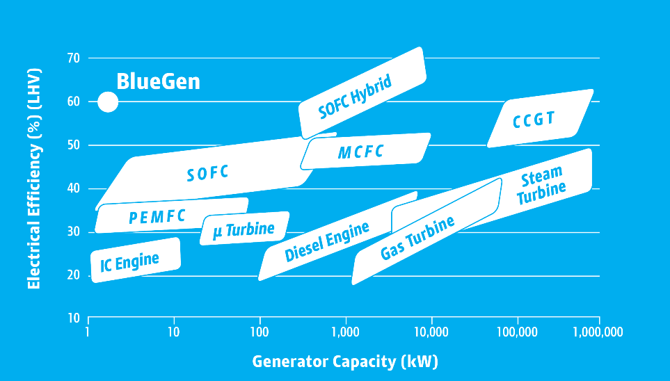
Figure 22. Distribution of main cogeneration systems.