

Internet Routing Architectures, Second Edition
Example 12-62 shows RTG's IP routing table; note how RTG follows the default toward RTF.
Example 12-62. RTG IP Routing Table
RTG#show ip route
Codes: C - connected, S - static, I - IGRP, R - RIP, M - mobile, B - BGP D - EIGRP, EX - EIGRP external, O - OSPF, IA - OSPF inter area N1 - OSPF NSSA external type 1, N2 - OSPF NSSA external type 2 E1 - OSPF external type 1, E2 - OSPF external type 2, E - EGP
i - IS-IS, L1 - IS-IS level-1, L2 - IS-IS level-2,
* - candidate default U - per-user static route, o - ODR
Gateway of last resort is 172.16.50.1 to network 0.0.0.0
172.16.0.0/16 is subnetted, 4 subnets
i L1 172.16.220.0/24 [115/20] via 172.16.70.1, Serial0 i L1 172.16.20.0/24 [115/20] via 172.16.70.1, Serial0 C 172.16.50.0/24 is directly connected, Serial1
C 172.16.70.0/24 is directly connected, Serial0 i*L2 0.0.0.0/0 [115/10] via 172.16.50.1, Serial1
Policy Routing
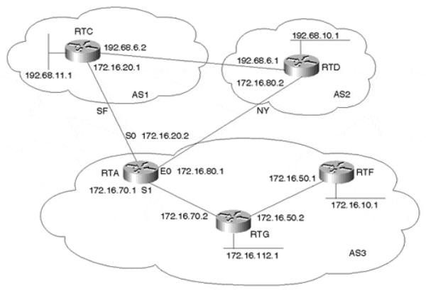
This section demonstrates how policy routing can be used to direct the traffic based on the source IP address rather than the destination IP address. Figure 12-12 shows a router, RTA, that is running BGP with two providers, AS1 and AS2. Internal routers such as RTG and RTF are running IGP only (OSPF) and are following a default route toward RTA.
Figure 12-12. Policy Routing Scenario
page 361
Internet Routing Architectures, Second Edition
RTA wants to set policy routing in such a way that traffic coming over the serial line S1 from RTG is directed toward AS2 if the source is network 172.16.10.0/24. Traffic coming from RTG with source 172.16.112.0/24 is to be directed toward AS1; in case of a link failure to AS1, the traffic will go to AS2. For all other source IP addresses, follow normal routing.
Example 12-63 shows the configuration for RTA to satisfy the criteria of this policy routing setup.
Example 12-63. Policy Routing: RTA Configuration
interface Ethernet0
ip address 172.16.80.1 255.255.255.0 interface Serial1
ip address 172.16.70.1 255.255.255.0 ip policy route-map CHECK_SOURCE router ospf 10
passive-interface Serial0 passive-interface Ethernet0
network 172.16.0.0 0.0.255.255 area 0 default-information originate always router bgp 3
network 172.16.50.0 mask 255.255.255.0 network 172.16.70.0 mask 255.255.255.0 network 172.16.10.0 mask 255.255.255.0 network 172.16.112.0 mask 255.255.255.0 neighbor 172.16.20.1 remote-as 1 neighbor 172.16.20.1 filter-list 10 out neighbor 172.16.80.2 remote-as 2 neighbor 172.16.80.2 filter-list 10 out no auto-summary
ip as-path access-list 10 permit ^$ access-list 1 permit 172.16.10.0 0.0.0.255 access-list 2 permit 172.16.112.0 0.0.0.255 route-map CHECK_SOURCE permit 10
match ip address 1
set ip next-hop 172.16.80.2 route-map CHECK_SOURCE permit 20 match ip address 2
set ip next-hop 172.16.20.1 172.16.80.2
Policy routing is always applied to the incoming interface. Serial 1 is configured with the interface command ip policy route-map map-name. This will apply route map CHECK_SOURCE to all Serial 1 incoming traffic. The explanation of the route map follows:
•Instance 10: For all source IP addresses that come from 172.16.10.0/24, set the next hop to 172.16.80.2. If next hop 172.16.80.2 is unreachable, drop the packet.
•Instance 20: For all source IP addresses that come from 172.16.112.0/24, set the next hop to 172.16.20.1. If next hop 172.16.20.1 is unreachable, try sending the traffic to next hop 172.16.80.2.
•For all other source IP addresses, follow normal routing.
The policy routing route maps give you the option of choosing multiple next hops. This is necessary to always have a backup path. For all traffic that does not match the route maps, the router will follow normal routing. To illustrate, a traceroute will be done from RTG to
page 362
Internet Routing Architectures, Second Edition
192.68.10.1 from source IP address 172.16.112.1. Example 12-64 shows RTA's IP routing table.
Example 12-64. Policy Routing: RTA IP Routing Table
RTA#show ip route
Codes: C - connected, S - static, I - IGRP, R - RIP, M - mobile, B - BGP D - EIGRP, EX - EIGRP external, O - OSPF, IA - OSPF inter area N1 - OSPF NSSA external type 1, N2 - OSPF NSSA external type 2 E1 - OSPF external type 1, E2 - OSPF external type 2, E - EGP
i - IS-IS, L1 - IS-IS level-1, L2 - IS-IS level-2,
* - candidate default U - per-user static route, o - ODR
Gateway of last resort is not set
B192.68.10.0/24 [20/0] via 172.16.80.2, 00:30:09
B192.68.11.0/24 [20/0] via 172.16.20.1, 00:30:14 172.16.0.0/16 is subnetted, 5 subnets
O172.16.50.0/24 [110/69] via 172.16.70.2, 00:27:27, Serial1
C172.16.20.0/24 is directly connected, Serial0
C 172.16.80.0/24 is directly connected, Ethernet0
C 172.16.70.0/24 is directly connected, Serial1
Example 12-65 demonstrates a traceroute from RTG with a source of 172.16.112.1 and a destination of 192.68.10.1.
Example 12-65. Policy Routing: RTG traceroute
RTG#traceroute
Protocol [ip]:
Target IP address: 192.68.10.1
Source address: 172.16.112.1
Numeric display [n]:
Timeout in seconds [3]:
Probe count [3]:
Minimum Time to Live [1]:
Maximum Time to Live [30]:
Port Number [33434]:
Loose, Strict, Record, Timestamp, Verbose[none]:
Type escape sequence to abort.
Tracing the route to gateway.aeg-aas.de (192.68.10.1)
1 172.16.70.1 4 msec 4 msec 0 msec
2 172.16.20.1 4 msec 4 msec 4 msec
3 192.68.6.1 4 msec 4 msec 4 msec
Notice how RTA has taken next hop 172.16.20.1 (the second line in the traceroute output) to reach 192.68.10.0/24, even though RTA's routing table indicates that 192.68.10.0/24 should be reached with next hop 172.16.80.2.
This second attempt shows what will happen if Serial 0 is down and next hop 172.16.20.1 is unreachable. The next step is to perform a traceroute from RTG with a source of 172.16.112.1 and a destination of 192.68.10.1 while Serial 0 is down, as demonstrated in Example 12-66.
page 363
Internet Routing Architectures, Second Edition
Example 12-66. Policy Routing: RTG traceroute
RTG#traceroute
Protocol [ip]:
Target IP address: 192.68.10.1
Source address: 172.16.112.1
Numeric display [n]:
Timeout in seconds [3]:
Probe count [3]:
Minimum Time to Live [1]:
Maximum Time to Live [30]:
Port Number [33434]:
Loose, Strict, Record, Timestamp, Verbose[none]:
Type escape sequence to abort.
Tracing the route to gateway.aeg-aas.de (192.68.10.1)
1 172.16.70.1 0 msec 4 msec 4 msec
2 172.16.80.2 8 msec 4 msec 4 msec
The output in Example 12-66 reveals that RTA has taken the alternative next hop 172.16.80.2.
Before implementing any policy-based routing solutions, it's important that you understand the policy routing support and performance implications of the version of IOS and platform you're using. For additional information, consult the appropriate Cisco Command Reference, Configuration Guidelines, and Release Notes for your specific hardware and software versions.
Route Reflectors
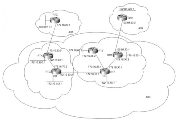
This section illustrates a practical use of route reflectors and peer groups. In Figure 12-13, RTG and RTA form a route reflector cluster, where RTG is the route reflector. RTF, RTE, and RTD form another cluster where RTF is the route reflector. RTG and RTF are part of a peer group called REFLECTORS; if there are other route reflectors, all should IBGP peer in a full mesh. RTF puts all its clients in a peer group called CLIENTS, where common policies can be applied.
page 364
Internet Routing Architectures, Second Edition
Figure 12-13. Route Reflectors
Clients are identified on the route reflector servers by configuring route-reflector-client following the neighbor x.x.x.x parameter. Traditionally, there was an IOS limitation that required client-to-client reflection to be disabled if the clients were members of a BGP peer group. This is no longer a restriction. Full IBGP mesh will be maintained inside the RTF- RTD-RTE cluster, and the clients will peer only with the associated route reflector. Example 12-67 shows the configuration for RTF.
Example 12-67. Route Reflectors: RTF Configuration
router bgp 3
no synchronization
network 172.16.65.0 mask 255.255.255.192 network 172.16.50.0 mask 255.255.255.0 network 172.16.25.0 mask 255.255.255.0 network 172.16.30.0 mask 255.255.255.0 neighbor REFLECTORS peer-group
neighbor REFLECTORS remote-as 3 neighbor CLIENTS peer-group neighbor CLIENTS remote-as 3
neighbor CLIENTS route-reflector-client neighbor 172.16.25.2 peer-group CLIENTS neighbor 172.16.30.2 peer-group CLIENTS neighbor 172.16.50.2 peer-group REFLECTORS no auto-summary
Because RTF provides the only available internal path out of the cluster, RTD and RTE are configured as clients of RTF, and RTF is configured as the route reflector. Together, the three
page 365
Internet Routing Architectures, Second Edition
routers comprise what's referred to as a cluster in route reflection terminology. From RTD and RTE's perspective, the BGP peering session with RTF is a normal IBGP session. In other words, the client need not be aware that it is a client. (Note that this was one of the requirements for designing route reflection—that the clients need not know that they're clients.) Examples 12-68 through 12-70 show the configurations for RTD, RTG, and RTA, respectively.
Example 12-68. Route Reflectors: RTD Configuration
router bgp 3
no synchronization
network 172.16.90.0 mask 255.255.255.0 network 172.16.30.0 mask 255.255.255.0 neighbor 172.16.30.1 remote-as 3 neighbor 172.16.30.1 next-hop-self neighbor 192.68.20.2 remote-as 2 neighbor 192.68.20.2 filter-list 10 out no auto-summary
ip as-path access-list 10 permit ^$
Example 12-69. Route Reflectors: RTG Configuration
router bgp 3
no synchronization
network 172.16.112.0 mask 255.255.255.0 network 172.16.50.0 mask 255.255.255.0 network 172.16.70.0 mask 255.255.255.0 neighbor 172.16.50.1 remote-as 3 neighbor 172.16.70.1 remote-as 3
neighbor 172.16.70.1 route-reflector-client no auto-summary
Example 12-70. Route Reflectors: RTA Configuration
router bgp 3
no synchronization
network 172.16.220.0 mask 255.255.255.0 network 172.16.70.0 mask 255.255.255.0 neighbor 172.16.20.1 remote-as 1 neighbor 172.16.20.1 filter-list 10 out neighbor 172.16.70.2 remote-as 3 neighbor 172.16.70.2 next-hop-self
no auto-summary
ip as-path access-list 10 permit ^$
The BGP table in Example 12-71 shows how RTD sees some of the routes that are being reflected into its own cluster.
Example 12-71. Route Reflectors: RTD BGP Table
RTD#show ip bgp 172.16.220.0
BGP routing table entry for 172.16.220.0/24, version 52
Paths: (1 available, best #1)
Local
page 366